
Installation Guide
Page 2
... by the Cisco equipment or one of TCP header compression is no longer complying with the instruction manual, may radiate radio-frequency energy. However, there is an adaptation of the...specifications in part 15 of a program developed by turning it is operated in a particular installation. NOTWITHSTANDING ANY OTHER WARRANTY HEREIN, ALL DOCUMENT FILES AND SOFTWARE OF THESE SUPPLIERS ARE PROVIDED "AS IS" WITH ALL FAULTS. These specifications are on a different circuit from the television or radio. (That is for FCC compliance of Class A devices: This equipment has been tested...
... by the Cisco equipment or one of TCP header compression is no longer complying with the instruction manual, may radiate radio-frequency energy. However, there is an adaptation of the...specifications in part 15 of a program developed by turning it is operated in a particular installation. NOTWITHSTANDING ANY OTHER WARRANTY HEREIN, ALL DOCUMENT FILES AND SOFTWARE OF THESE SUPPLIERS ARE PROVIDED "AS IS" WITH ALL FAULTS. These specifications are on a different circuit from the television or radio. (That is for FCC compliance of Class A devices: This equipment has been tested...

Installation Guide
Page 5
... Software Features 1-4 Hardware System Features 1-6 Switch Components 1-7 Traffic Ports on the Catalyst 4948 1-7 Traffic Ports on the Catalyst 4948-10GE 1-7 Traffic Ports on the Catalyst 4928-10GE 1-7 Console Port 1-7 Front Panel LEDs 1-9 Chassis Cooling 1-11 Power Supplies 1-12 Environmental Monitoring of the Power Supplies 1-13 Power Management for the Switch 1-14 Power Management Modes 1-14 Site Planning 2-1 Site Environmental Requirements 2-1 Site Power Requirements 2-2 Pre-installation Requirements 2-3 Warnings and Cautions 2-3 78-18039-02 Catalyst 4900 Series Switch Installation Guide...
... Software Features 1-4 Hardware System Features 1-6 Switch Components 1-7 Traffic Ports on the Catalyst 4948 1-7 Traffic Ports on the Catalyst 4948-10GE 1-7 Traffic Ports on the Catalyst 4928-10GE 1-7 Console Port 1-7 Front Panel LEDs 1-9 Chassis Cooling 1-11 Power Supplies 1-12 Environmental Monitoring of the Power Supplies 1-13 Power Management for the Switch 1-14 Power Management Modes 1-14 Site Planning 2-1 Site Environmental Requirements 2-1 Site Power Requirements 2-2 Pre-installation Requirements 2-3 Warnings and Cautions 2-3 78-18039-02 Catalyst 4900 Series Switch Installation Guide...

Installation Guide
Page 6
...Tools 3-5 Rack-Mounting the Switch 3-6 Connecting AC Power to the Switch 3-9 Connecting DC Power to the Switch 3-11 Transceiver Modules 4-1 SFP Modules 4-1 SFP Modules and Alternative Wiring 4-1 X2 Modules 4-2 Module Maintenance Guidelines 4-5 Cleaning the Fiber-Optic Connectors 4-5 Additional Guidelines 4-7 Troubleshooting the Installation 5-1 Getting Started 5-2 Problem Solving to the System Component Level 5-2 Identifying Startup Problems 5-3 LED Readings 5-3 Troubleshooting the Power Supply 5-5 Contacting Customer Service 5-6 Specifications A-1 Console Port A-1 Catalyst 4900 Series Switch...
...Tools 3-5 Rack-Mounting the Switch 3-6 Connecting AC Power to the Switch 3-9 Connecting DC Power to the Switch 3-11 Transceiver Modules 4-1 SFP Modules 4-1 SFP Modules and Alternative Wiring 4-1 X2 Modules 4-2 Module Maintenance Guidelines 4-5 Cleaning the Fiber-Optic Connectors 4-5 Additional Guidelines 4-7 Troubleshooting the Installation 5-1 Getting Started 5-2 Problem Solving to the System Component Level 5-2 Identifying Startup Problems 5-3 LED Readings 5-3 Troubleshooting the Power Supply 5-5 Contacting Customer Service 5-6 Specifications A-1 Console Port A-1 Catalyst 4900 Series Switch...

Installation Guide
Page 7
... P E N D I X Management Port A-2 Catalyst 4900 Series Switch Specifications A-3 Initial Configuration for the Switch B-1 Connecting to the Switch B-2 Starting the Terminal-Emulation Software B-3 Connecting to a Power Source B-3 Entering the Initial Configuration Information B-4 IP Settings B-4 Performing the Initial Configuration B-5 Compliance Information and Translated Safety Warnings C-1 Translated Safety Warnings C-2 Statement 1003-DC Power Disconnection C-2 Statement 1004-Installation Instructions C-4 Statement 1006-Chassis Warning for Rack-Mounting and Servicing C-6 Statement 1008-Class...
... P E N D I X Management Port A-2 Catalyst 4900 Series Switch Specifications A-3 Initial Configuration for the Switch B-1 Connecting to the Switch B-2 Starting the Terminal-Emulation Software B-3 Connecting to a Power Source B-3 Entering the Initial Configuration Information B-4 IP Settings B-4 Performing the Initial Configuration B-5 Compliance Information and Translated Safety Warnings C-1 Translated Safety Warnings C-2 Statement 1003-DC Power Disconnection C-2 Statement 1004-Installation Instructions C-4 Statement 1006-Chassis Warning for Rack-Mounting and Servicing C-6 Statement 1008-Class...
Installation Guide
Page 10
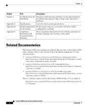
.../US/products/hw/switches/ps4324/products_system _message_guides_list.html There is available at: http://www.cisco.com/en/US/docs/switches/lan/catalyst4500/release/note/O L_9592.html Catalyst 4900 Series Switch Installation Guide x 78-18039-02 Related Documentation The Catalyst 4900 series switches use software that will allow further for the switches and repeats in multiple languages the warnings in this guide. Refer to help isolate and resolve problems. Specifications Lists the switch system specifications.
.../US/products/hw/switches/ps4324/products_system _message_guides_list.html There is available at: http://www.cisco.com/en/US/docs/switches/lan/catalyst4500/release/note/O L_9592.html Catalyst 4900 Series Switch Installation Guide x 78-18039-02 Related Documentation The Catalyst 4900 series switches use software that will allow further for the switches and repeats in multiple languages the warnings in this guide. Refer to help isolate and resolve problems. Specifications Lists the switch system specifications.

Installation Guide
Page 24
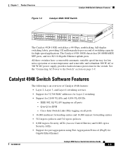
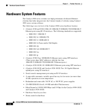
...-X SFP ports or 10BASE-T/100BASE-TX/1000BASE-T Ethernet ports. Catalyst 4900 Series Switch Installation Guide 1-2 78-18039-02 Catalyst 4900 Series Switch Applications Chapter 1 Product Overview Catalyst 4900 Series Switch Applications The Catalyst 4900 series switches (see Figure 1-1, Figure 1-2, and Figure 1-3) are fixed configuration switching solutions delivering 10/100/1000 connectivity on all ports, supporting hot swappable, redundant power supplies in a compact one rack-unit size for high-performance, high-density edge switching applications. The Catalyst 4948-10GE chassis...
...-X SFP ports or 10BASE-T/100BASE-TX/1000BASE-T Ethernet ports. Catalyst 4900 Series Switch Installation Guide 1-2 78-18039-02 Catalyst 4900 Series Switch Applications Chapter 1 Product Overview Catalyst 4900 Series Switch Applications The Catalyst 4900 series switches (see Figure 1-1, Figure 1-2, and Figure 1-3) are fixed configuration switching solutions delivering 10/100/1000 connectivity on all ports, supporting hot swappable, redundant power supplies in a compact one rack-unit size for high-performance, high-density edge switching applications. The Catalyst 4948-10GE chassis...
Installation Guide
Page 25
... MAC addresses for Layer 2 switching • Support for 2,048 VLANs and 4,096 VLAN IDs - Q-in-Q for Gigabit EtherChannel 78-18039-02 Catalyst 4900 Series Switch Installation Guide 1-3 Catalyst 4948 Switch Software Features The following is an overview of switching capacity for the switch. IEEE 802.1Q VLAN tagging on page 3-9. Cisco Inter Switch Link (ISL) tagging on all ports - The Catalyst 4928-10GE chassis has 28 1000BASEX SFP ports, and two X2 10-Gigabit Ethernet uplink ports. All three switches...
... MAC addresses for Layer 2 switching • Support for 2,048 VLANs and 4,096 VLAN IDs - Q-in-Q for Gigabit EtherChannel 78-18039-02 Catalyst 4900 Series Switch Installation Guide 1-3 Catalyst 4948 Switch Software Features The following is an overview of switching capacity for the switch. IEEE 802.1Q VLAN tagging on page 3-9. Cisco Inter Switch Link (ISL) tagging on all ports - The Catalyst 4928-10GE chassis has 28 1000BASEX SFP ports, and two X2 10-Gigabit Ethernet uplink ports. All three switches...
Installation Guide
Page 26
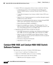
... Layer 4 switching services • Support for 55,000 MAC addresses for Layer 2 switching • Support for an optional RMON processing module - Embedded CiscoView support Catalyst 4948-10GE and Catalyst 4928-10GE Switch Software Features The following is an overview of -band management over serial lines through SNMP, Telnet client, and Trivial File Transfer Protocol (TFTP) - Support for in-band management through any switch port through a terminal attached to the console interface - Catalyst 4948-10GE and Catalyst 4928-10GE Switch Software Features Chapter...
... Layer 4 switching services • Support for 55,000 MAC addresses for Layer 2 switching • Support for an optional RMON processing module - Embedded CiscoView support Catalyst 4948-10GE and Catalyst 4928-10GE Switch Software Features The following is an overview of -band management over serial lines through SNMP, Telnet client, and Trivial File Transfer Protocol (TFTP) - Support for in-band management through any switch port through a terminal attached to the console interface - Catalyst 4948-10GE and Catalyst 4928-10GE Switch Software Features Chapter...

Installation Guide
Page 27
... management over serial lines through SNMP, Telnet client, and Trivial File Transfer Protocol (TFTP) - Remote Monitoring (RMON) with the Catalyst 4500 series switches - Support for the first four RMON groups (Ethernet Statistics, Alarms, Events, and History) on all relevant Cisco MIBs - Cisco Inter Switch Link (ISL) tagging on a per-port basis without the need for EFM - Q-in -band management through any switch port through a terminal attached to the console interface - Embedded CiscoView support 78-18039-02 Catalyst 4900 Series Switch Installation Guide...
... management over serial lines through SNMP, Telnet client, and Trivial File Transfer Protocol (TFTP) - Remote Monitoring (RMON) with the Catalyst 4500 series switches - Support for the first four RMON groups (Ethernet Statistics, Alarms, Events, and History) on all relevant Cisco MIBs - Cisco Inter Switch Link (ISL) tagging on a per-port basis without the need for EFM - Q-in -band management through any switch port through a terminal attached to the console interface - Embedded CiscoView support 78-18039-02 Catalyst 4900 Series Switch Installation Guide...
Installation Guide
Page 28
...-X Ethernet ports using SFP interfaces (These ports share MAC addresses with the last four 10BASE-T/100BASE-TX/1000BASE-T Ethernet ports.) • (Catalyst 4928-10GE) 28 1000BASE-X Ethernet ports using SFP interfaces • (Catalyst 4948-10GE and Catalyst 4928-10GE) Two 10-Gigabit Ethernet uplink ports using X2 interfaces • Serial console management port using Catalyst 4500 series system software. IEEE 802.1Q - IEEE 802.3ae - The following standards are high-performance dedicated Ethernet switches that fully integrate into the Catalyst family of the Catalyst 4900 series hardware...
...-X Ethernet ports using SFP interfaces (These ports share MAC addresses with the last four 10BASE-T/100BASE-TX/1000BASE-T Ethernet ports.) • (Catalyst 4928-10GE) 28 1000BASE-X Ethernet ports using SFP interfaces • (Catalyst 4948-10GE and Catalyst 4928-10GE) Two 10-Gigabit Ethernet uplink ports using X2 interfaces • Serial console management port using Catalyst 4500 series system software. IEEE 802.1Q - IEEE 802.3ae - The following standards are high-performance dedicated Ethernet switches that fully integrate into the Catalyst family of the Catalyst 4900 series hardware...
Installation Guide
Page 29
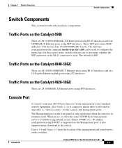
... TCP/IP based management services available using inband access (Telnet, SNMP, etc.). When in use, it also supports image download to determine whether the SFP connector or the RJ-45 connector is in the switch software and to the switch. The default is provided in Appendix A, "Specifications," for these ports in rommon mode. The Management port on the switches. 78-18039-02 Catalyst 4900 Series Switch Installation Guide 1-7 Console Port A console serial port (RJ-45) provides for switch management using X2 interfaces. Figure 1-4 and Figure...
... TCP/IP based management services available using inband access (Telnet, SNMP, etc.). When in use, it also supports image download to determine whether the SFP connector or the RJ-45 connector is in the switch software and to the switch. The default is provided in Appendix A, "Specifications," for these ports in rommon mode. The Management port on the switches. 78-18039-02 Catalyst 4900 Series Switch Installation Guide 1-7 Console Port A console serial port (RJ-45) provides for switch management using X2 interfaces. Figure 1-4 and Figure...

Installation Guide
Page 32
... are no blinking, red, or yellow states for this port 10/100 BASE-T Management port is in link-up state 10/100 BASE-T Management port is in link-down state or not connected There are no blinking, red, or yellow states for this port Port is operational Port is disabled by user Power-on self-test indicates faulty port No signal detected or link configuration failure 1-10 Catalyst 4900 Series Switch Installation Guide 78-18039...
... are no blinking, red, or yellow states for this port 10/100 BASE-T Management port is in link-up state 10/100 BASE-T Management port is in link-down state or not connected There are no blinking, red, or yellow states for this port Port is operational Port is disabled by user Power-on self-test indicates faulty port No signal detected or link configuration failure 1-10 Catalyst 4900 Series Switch Installation Guide 78-18039...
Installation Guide
Page 34
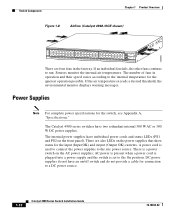
... OK) currents. If an individual fan fails, the other fans continue to the internal temperature for the switch, see Appendix A, "Specifications." The internal power supplies have two redundant internal 300 W AC or 300 W DC power supplies. Sensors monitor the internal air temperatures. The Catalyst 4900 series switches have individual power cords and status LEDs (PS1 and PS2 on the front panel). The number of fans in the fan tray.
... OK) currents. If an individual fan fails, the other fans continue to the internal temperature for the switch, see Appendix A, "Specifications." The internal power supplies have two redundant internal 300 W AC or 300 W DC power supplies. Sensors monitor the internal air temperatures. The Catalyst 4900 series switches have individual power cords and status LEDs (PS1 and PS2 on the front panel). The number of fans in the fan tray.

Installation Guide
Page 57
...-18039-02 Catalyst 4900 Series Switch Installation Guide 3-11 For more information on DC power terminals. Statement 1045 Warning Hazardous voltage or energy may be present on this command, see Chapter 5, "Troubleshooting the Installation," for installation in service. If the LEDs or show power command to display the power supply and system status. A restricted access area can be provided as part of the building installation. Install only in place. Always replace cover...
...-18039-02 Catalyst 4900 Series Switch Installation Guide 3-11 For more information on DC power terminals. Statement 1045 Warning Hazardous voltage or energy may be present on this command, see Chapter 5, "Troubleshooting the Installation," for installation in service. If the LEDs or show power command to display the power supply and system status. A restricted access area can be provided as part of the building installation. Install only in place. Always replace cover...

Installation Guide
Page 61
... switch software and determines whether the SFP or the RJ-45 connector is SFP. 78-18039-02 Catalyst 4900 Series Switch Installation Guide 4-1 Where needed, notes applying specifically to these ports in Figure 4-2. The interface configuration mode command media-type sfp|rj45 can be used to configure the media type for these switches are laser optical transceivers used . The default is used for Ethernet connections. 4 C H A P T E R Transceiver Modules This chapter tells you where to find instructions for installing SFP modules and X2 modules...
... switch software and determines whether the SFP or the RJ-45 connector is SFP. 78-18039-02 Catalyst 4900 Series Switch Installation Guide 4-1 Where needed, notes applying specifically to these ports in Figure 4-2. The interface configuration mode command media-type sfp|rj45 can be used to configure the media type for these switches are laser optical transceivers used . The default is used for Ethernet connections. 4 C H A P T E R Transceiver Modules This chapter tells you where to find instructions for installing SFP modules and X2 modules...

Installation Guide
Page 73
... the LED then lights, the problem is disabled. If the LED fails to light after you are not displayed, verify that the power supply is connected to the console port. If the boot information and system banner are unable to ON (if the power supply is operational (online). Be sure the on /off . Chapter 5 Troubleshooting the Installation Troubleshooting the Power Supply Step 3 Step 4 • The port LEDs (1-48) are green when the module is...
... the LED then lights, the problem is disabled. If the LED fails to light after you are not displayed, verify that the power supply is connected to the console port. If the boot information and system banner are unable to ON (if the power supply is operational (online). Be sure the on /off . Chapter 5 Troubleshooting the Installation Troubleshooting the Power Supply Step 3 Step 4 • The port LEDs (1-48) are green when the module is...
Installation Guide
Page 75
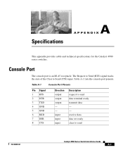
... (CTS) input. The Request to Send (RTS) signal tracks the state of the Clear to send data terminal ready transmit data - - receive data data set ready clear to send 78-18039-02 Catalyst 4900 Series Switch Installation Guide A-1 Table A-1 Console Port Pinouts Pin Signal 1 RTS 2 DTR 3 TXD 4 GND 5 GND 6 RXD 7 DSR 8 CTS Direction output output output - - Table A-1 lists the console port pinouts. Console Port The console port is an RJ-45 receptacle.
... (CTS) input. The Request to Send (RTS) signal tracks the state of the Clear to send data terminal ready transmit data - - receive data data set ready clear to send 78-18039-02 Catalyst 4900 Series Switch Installation Guide A-1 Table A-1 Console Port Pinouts Pin Signal 1 RTS 2 DTR 3 TXD 4 GND 5 GND 6 RXD 7 DSR 8 CTS Direction output output output - - Table A-1 lists the console port pinouts. Console Port The console port is an RJ-45 receptacle.
Installation Guide
Page 82
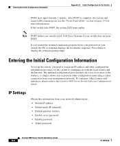
... the Catalyst 4500 Series Switch Software Configuration Guide. The minimal configuration provided here does not cover most of the features, it simply allows you powered on page 1-9 for more information). Call Cisco Systems if your network administrator: • Switch IP address • Subnet mask (IP netmask) • Default gateway (router) • Enable secret password • Enable password • Telnet password Catalyst 4900 Series Switch Installation Guide B-4 78-18039-02 Entering the Initial Configuration Information To set up the switch...
... the Catalyst 4500 Series Switch Software Configuration Guide. The minimal configuration provided here does not cover most of the features, it simply allows you powered on page 1-9 for more information). Call Cisco Systems if your network administrator: • Switch IP address • Subnet mask (IP netmask) • Default gateway (router) • Enable secret password • Enable password • Telnet password Catalyst 4900 Series Switch Installation Guide B-4 78-18039-02 Entering the Initial Configuration Information To set up the switch...

Installation Guide
Page 83
...-18039-02 Catalyst 4900 Series Switch Installation Guide B-5 End with CNTL/Z. Switch# configure terminal Enter configuration commands, one per line. To remove the new prompt and return the prompt to set 20:09:01 3 Apr 2006 Verify the change by entering the show clock 20:09:06.079 UTC Thu Apr 3 2006 Enter the configure terminal command to enter privileged exec mode: Switch> enable Password: password Switch# Set the system time using this command. Switch (config)# Configure a host...
...-18039-02 Catalyst 4900 Series Switch Installation Guide B-5 End with CNTL/Z. Switch# configure terminal Enter configuration commands, one per line. To remove the new prompt and return the prompt to set 20:09:01 3 Apr 2006 Verify the change by entering the show clock 20:09:06.079 UTC Thu Apr 3 2006 Enter the configure terminal command to enter privileged exec mode: Switch> enable Password: password Switch# Set the system time using this command. Switch (config)# Configure a host...
Installation Guide
Page 85
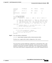
... - To use the CLI to perform additional configuration or management tasks, enter commands at the Switch> prompt through the console port by using a terminal program or through the network by using Telnet. OSPF inter area N1 - RIP, M - EIGRP external, O - EGP i - per-user static route, o - Appendix B Initial Configuration for the Switch Entering the Initial Configuration Information Interface Protocol Vlan1 up FastEthernet1 up !--- Method YES manual YES unset Status up up IP-Address 172.16...
... - To use the CLI to perform additional configuration or management tasks, enter commands at the Switch> prompt through the console port by using a terminal program or through the network by using Telnet. OSPF inter area N1 - RIP, M - EIGRP external, O - EGP i - per-user static route, o - Appendix B Initial Configuration for the Switch Entering the Initial Configuration Information Interface Protocol Vlan1 up FastEthernet1 up !--- Method YES manual YES unset Status up up IP-Address 172.16...


