Installation Guide
Page 2
... a Class B digital device in accordance with the instruction manual, may be required to part 15 of actual IP addresses in illustrative content is not installed in a particular installation. All rights reserved. and Access Registrar, Aironet, AsyncOS, Bringing the Meeting To You, Catalyst, CCDA, CCDP, CCIE, CCIP, CCNA, CCNP, CCSP, CCVP, Cisco, the Cisco Certified Internetwork Expert logo, Cisco IOS, Cisco Press, Cisco Systems, Cisco Systems Capital...
... a Class B digital device in accordance with the instruction manual, may be required to part 15 of actual IP addresses in illustrative content is not installed in a particular installation. All rights reserved. and Access Registrar, Aironet, AsyncOS, Bringing the Meeting To You, Catalyst, CCDA, CCDP, CCIE, CCIP, CCNA, CCNP, CCSP, CCVP, Cisco, the Cisco Certified Internetwork Expert logo, Cisco IOS, Cisco Press, Cisco Systems, Cisco Systems Capital...

Installation Guide
Page 5
...2-53 Troubleshooting 3-1 Diagnosing Problems 3-1 Verify Switch POST Results 3-1 Verify Switch LEDs 3-2 Verify Switch Connections 3-2 Bad or Damaged Cable 3-2 Ethernet and Fiber Cables 3-2 Link Status 3-3 Transceiver Issues 3-3 Port and Interface Settings 3-3 Ping End Device 3-3 Spanning Tree Loops 3-4 Verify Switch Performance 3-4 Speed, Duplex, and Autonegotiation 3-4 Autonegotiation and NIC 3-4 Cabling Distance 3-5 How to Clear the Switch IP Address and Configuration 3-5 How to Recover Passwords 3-5 Finding the Switch Serial Number 3-6 Technical Specifications A-1 Installation In a Hazardous...
...2-53 Troubleshooting 3-1 Diagnosing Problems 3-1 Verify Switch POST Results 3-1 Verify Switch LEDs 3-2 Verify Switch Connections 3-2 Bad or Damaged Cable 3-2 Ethernet and Fiber Cables 3-2 Link Status 3-3 Transceiver Issues 3-3 Port and Interface Settings 3-3 Ping End Device 3-3 Spanning Tree Loops 3-4 Verify Switch Performance 3-4 Speed, Duplex, and Autonegotiation 3-4 Autonegotiation and NIC 3-4 Cabling Distance 3-5 How to Clear the Switch IP Address and Configuration 3-5 How to Recover Passwords 3-5 Finding the Switch Serial Number 3-6 Technical Specifications A-1 Installation In a Hazardous...
Installation Guide
Page 9
... Ethernet and local area networking. OL-13017-01 Cisco IE 3000 Switch Hardware Installation Guide ix Note Means reader take note. Notes contain helpful suggestions or references to materials not contained in equipment damage or loss of the Cisco IE 3000 switches. Purpose This guide documents the hardware features of data. For information about the standard Cisco IOS Release 12.1 or 12.2 commands, see the switch getting started guide, the switch software configuration guide...
... Ethernet and local area networking. OL-13017-01 Cisco IE 3000 Switch Hardware Installation Guide ix Note Means reader take note. Notes contain helpful suggestions or references to materials not contained in equipment damage or loss of the Cisco IE 3000 switches. Purpose This guide documents the hardware features of data. For information about the standard Cisco IOS Release 12.1 or 12.2 commands, see the switch getting started guide, the switch software configuration guide...
Installation Guide
Page 11
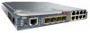
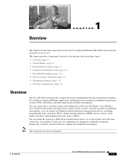
... that describe the Cisco Industrial Ethernet (IE) 3000 switch, hereafter referred to office networking devices like Cisco IP Phones, Cisco Wireless Access Points workstations, and other devices such as the switch. Its components are common in a standard 19-inch rack. This chapter provides a functional overview of the switches and covers these topics: • Overview, page 1-1 • Switch Models, page 1-2 • Front-Panel Description, page 1-2 • Compact Flash Memory Card, page 1-11...
... that describe the Cisco Industrial Ethernet (IE) 3000 switch, hereafter referred to office networking devices like Cisco IP Phones, Cisco Wireless Access Points workstations, and other devices such as the switch. Its components are common in a standard 19-inch rack. This chapter provides a functional overview of the switches and covers these topics: • Overview, page 1-1 • Switch Models, page 1-2 • Front-Panel Description, page 1-2 • Compact Flash Memory Card, page 1-11...

Installation Guide
Page 12
...; Console Port, page 1-6 • LEDs, page 1-6 The switch front panel contains the ports, the LEDs, and the power and relay connectors. The Cisco IE-3000-4TC and the Cisco IE-3000-8TC are the switch models, and the Cisco IEM-3000-8TM and the Cisco IEM-3000-8FM are expansion modules that you can connect to the Switch" section on page 2-5. . For instructions on how to connect the expansion modules...
...; Console Port, page 1-6 • LEDs, page 1-6 The switch front panel contains the ports, the LEDs, and the power and relay connectors. The Cisco IE-3000-4TC and the Cisco IE-3000-8TC are the switch models, and the Cisco IEM-3000-8TM and the Cisco IEM-3000-8FM are expansion modules that you can connect to the Switch" section on page 2-5. . For instructions on how to connect the expansion modules...

Installation Guide
Page 15
... device supports it) and configures itself accordingly. These ports use a small-form-factor fixed (SFF) fiber-optic transceiver module that both ports are field-replaceable, providing the uplink interfaces when inserted in an SFP module slot. When connecting the switch to workstations, servers, routers, and Cisco IP Phones, be configured as either a 10/100/1000 port or as fixed 10, 100, or 1000 Mb/s (Gigabit) Ethernet ports and can use the mdix auto interface configuration command in the command-line interface (CLI...
... device supports it) and configures itself accordingly. These ports use a small-form-factor fixed (SFF) fiber-optic transceiver module that both ports are field-replaceable, providing the uplink interfaces when inserted in an SFP module slot. When connecting the switch to workstations, servers, routers, and Cisco IP Phones, be configured as either a 10/100/1000 port or as fixed 10, 100, or 1000 Mb/s (Gigabit) Ethernet ports and can use the mdix auto interface configuration command in the command-line interface (CLI...

Installation Guide
Page 16
... connect a switch to -DB-9 adapter cable. Console Port You can operate with a single power source or with either open , so under power failure conditions, the contacts are visible through the console port and the supplied RJ-45-to a PC through the GUI management applications-the Cisco Network Assistant application for multiple switches and the device manager GUI for environmental, power supply, and port status alarm conditions and can use the CLI to configure and to polarity. LEDs...
... connect a switch to -DB-9 adapter cable. Console Port You can operate with a single power source or with either open , so under power failure conditions, the contacts are visible through the console port and the supplied RJ-45-to a PC through the GUI management applications-the Cisco Network Assistant application for multiple switches and the device manager GUI for environmental, power supply, and port status alarm conditions and can use the CLI to configure and to polarity. LEDs...
Installation Guide
Page 24
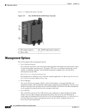
... output connector 2 Status LED 3 AC/DC input power connector Management Options The switch supports these management options: • Cisco Network Assistant Cisco Network Assistant is a PC-based network management GUI application optimized for more information, see the Getting Started with Cisco Network Assistant guide on Cisco IOS software and is in your management station directly to manage individual and standalone switches. This web interface offers quick configuration and monitoring. For more information. 1-14 Cisco IE 3000 Switch Hardware Installation Guide OL-13017-01...
... output connector 2 Status LED 3 AC/DC input power connector Management Options The switch supports these management options: • Cisco Network Assistant Cisco Network Assistant is a PC-based network management GUI application optimized for more information, see the Getting Started with Cisco Network Assistant guide on Cisco IOS software and is in your management station directly to manage individual and standalone switches. This web interface offers quick configuration and monitoring. For more information. 1-14 Cisco IE 3000 Switch Hardware Installation Guide OL-13017-01...

Installation Guide
Page 62
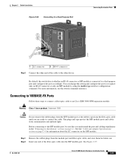
... auto-MDIX feature is enabled by default. When connecting to 1000BASE-T-compatible devices, to an RJ-45 connector on both ends of attached devices. For configuration information for configuring the Ethernet ports: • Let the ports autonegotiate both speed and duplex. • Set the port speed and duplex parameters on the front panel. Follow these methods for this feature, see the switch software configuration guide or the switch command reference. 2-36 Cisco IE 3000 Switch Hardware Installation Guide...
... auto-MDIX feature is enabled by default. When connecting to 1000BASE-T-compatible devices, to an RJ-45 connector on both ends of attached devices. For configuration information for configuring the Ethernet ports: • Let the ports autonegotiate both speed and duplex. • Set the port speed and duplex parameters on the front panel. Follow these methods for this feature, see the switch software configuration guide or the switch command reference. 2-36 Cisco IE 3000 Switch Hardware Installation Guide...
Installation Guide
Page 69
... change this setting and configure the port to an Cisco IEM-3000-8FM expansion module: Warning Class 1 laser product. See Figure 2-37. Step 1 Remove the rubber plugs from the fiber-optic cable until you understand the port and cabling stipulations in the "Preparing for future use. OL-13017-01 Cisco IE 3000 Switch Hardware Installation Guide 2-43 By default, the switch detects whether an RJ-45 connector or SFP module is connected...
... change this setting and configure the port to an Cisco IEM-3000-8FM expansion module: Warning Class 1 laser product. See Figure 2-37. Step 1 Remove the rubber plugs from the fiber-optic cable until you understand the port and cabling stipulations in the "Preparing for future use. OL-13017-01 Cisco IE 3000 Switch Hardware Installation Guide 2-43 By default, the switch detects whether an RJ-45 connector or SFP module is connected...

Installation Guide
Page 70
... 2-44 Cisco IE 3000 Switch Hardware Installation Guide OL-13017-01 The LED turns amber while the STP discovers the network topology and searches for solutions to the Power Converter The Cisco IE 3000 switch can be a problem with an optional AC/DC power converter (PWR-IE3000-AC). Connecting the Switch to cabling problems. If necessary, reconfigure and restart the switch or target device. Observe the port status LED. If an LED is off...
... 2-44 Cisco IE 3000 Switch Hardware Installation Guide OL-13017-01 The LED turns amber while the STP discovers the network topology and searches for solutions to the Power Converter The Cisco IE 3000 switch can be a problem with an optional AC/DC power converter (PWR-IE3000-AC). Connecting the Switch to cabling problems. If necessary, reconfigure and restart the switch or target device. Observe the port status LED. If an LED is off...
Installation Guide
Page 81
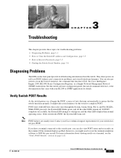
... test results on self-test (POST) failures, port-connectivity problems, and overall switch performance. If the switch fails POST, the System LED turns red. They show power-on the terminal. See the switch software configuration guide, the switch command reference, or the documentation that came with LED tests that the switch functions properly. While POST proceeds, the System LED blinks green, and all the other LEDs display their normal operating status. If you have a terminal connected to the console port...
... test results on self-test (POST) failures, port-connectivity problems, and overall switch performance. If the switch fails POST, the System LED turns red. They show power-on the terminal. See the switch software configuration guide, the switch command reference, or the documentation that came with LED tests that the switch functions properly. While POST proceeds, the System LED blinks green, and all the other LEDs display their normal operating status. If you have a terminal connected to the console port...
Installation Guide
Page 83
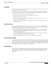
... command to the correct ports. • Verify that both devices have link. Check these items: • Bad or wrong SFP module. Re-enable the port if needed , re-enable the port or the interface. Port and Interface Settings A cause of the connectivity issue. OL-13017-01 Cisco IE 3000 Switch Hardware Installation Guide 3-3 Sometimes a cable appears to verify the port or module error-disabled, disabled, or shutdown status. See the"Cable and Adapter Specifications" section on the switch. Ping End Device Test the end device by trunk...
... command to the correct ports. • Verify that both devices have link. Check these items: • Bad or wrong SFP module. Re-enable the port if needed , re-enable the port or the interface. Port and Interface Settings A cause of the connectivity issue. OL-13017-01 Cisco IE 3000 Switch Hardware Installation Guide 3-3 Sometimes a cable appears to verify the port or module error-disabled, disabled, or shutdown status. See the"Cable and Adapter Specifications" section on the switch. Ping End Device Test the end device by trunk...
Installation Guide
Page 84
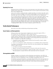
... the two ports to one of the connection. • If a remote device does not autonegotiate, configure the duplex settings on fiber-optic links. In aggressive mode, UDLD also detects unidirectional links due to match. By default, the switch ports and interfaces are mismatched between two switches, between a switch and a router, or between the switch and a workstation or server. To troubleshoot autonegotiation problems, try manually setting both ends of these circumstances: • A manually set speed or duplex...
... the two ports to one of the connection. • If a remote device does not autonegotiate, configure the duplex settings on fiber-optic links. In aggressive mode, UDLD also detects unidirectional links due to match. By default, the switch ports and interfaces are mismatched between two switches, between a switch and a router, or between the switch and a workstation or server. To troubleshoot autonegotiation problems, try manually setting both ends of these circumstances: • A manually set speed or duplex...
Installation Guide
Page 85
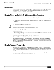
... switch continues to run Express Setup. You can enable or disable. To reset the password on page C-1 for recovering passwords. How to clear all the system LEDs turn red. 3. After the switch restarts, continue to boot. You can configure the switch by using the CLI setup procedure described in the getting started guide that a system administrator can also configure the switch by using Express Setup as described in Appendix D, "Configuring the Switch with the switch. If password recovery is disabled...
... switch continues to run Express Setup. You can enable or disable. To reset the password on page C-1 for recovering passwords. How to clear all the system LEDs turn red. 3. After the switch restarts, continue to boot. You can configure the switch by using the CLI setup procedure described in the getting started guide that a system administrator can also configure the switch by using Express Setup as described in Appendix D, "Configuring the Switch with the switch. If password recovery is disabled...
Installation Guide
Page 161
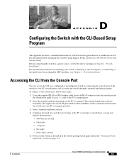
... 2, "Switch Installation." Start a terminal-emulation session. 4. No parity - Accessing the CLI from the Console Port You can access the CLI on page 2-11. For information about setting up the switch by connecting the console port of the PC or terminal to the small form-factor pluggable (SFP) modules, see the Cisco IE 3000 Switch Getting Started Guide. None (flow control) 5. D A P P E N D I X Configuring the Switch with the CLI-Based Setup Program This appendix provides a command-line interface (CLI)-based setup procedure for mounting your...
... 2, "Switch Installation." Start a terminal-emulation session. 4. No parity - Accessing the CLI from the Console Port You can access the CLI on page 2-11. For information about setting up the switch by connecting the console port of the PC or terminal to the small form-factor pluggable (SFP) modules, see the Cisco IE 3000 Switch Getting Started Guide. None (flow control) 5. D A P P E N D I X Configuring the Switch with the CLI-Based Setup Program This appendix provides a command-line interface (CLI)-based setup procedure for mounting your...
Installation Guide
Page 164
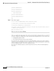
... appear: [0] Go to the IOS command prompt without saving this config. [1] Return back to the setup without saving this config. [2] Save this configuration or want to perform other management tasks, use one of these tools: • Command-line interface (CLI) • Cisco Network Assistant (for one or more switches) To use the Cisco Network Assistant, see the switch software configuration guide or the switch command reference. For configuration information, see the Getting Started with the CLI-Based Setup Program interface FastEthernet1/1 !
... appear: [0] Go to the IOS command prompt without saving this config. [1] Return back to the setup without saving this config. [2] Save this configuration or want to perform other management tasks, use one of these tools: • Command-line interface (CLI) • Cisco Network Assistant (for one or more switches) To use the Cisco Network Assistant, see the switch software configuration guide or the switch command reference. For configuration information, see the Getting Started with the CLI-Based Setup Program interface FastEthernet1/1 !
Installation Guide
Page 166
...-pair, 1000BASE-T ports C-6, C-8 D DC power, connecting to 2-16 to 2-22, B-19 to B-25 default characteristics of the console port 2-12, B-15 device manager described 1-14 to configure switch 2-53, B-59 diagnosing problems 3-1 dimensions A-2 to A-3 dual-purpose ports connectors and cables C-4 described 1-5 LEDs 1-11 IN-2 Cisco IE 3000 Switch Hardware Installation Guide duplex, troubleshooting 3-4 E electrical noise, avoiding 2-4, B-7 environmental ranges A-3 environmental temperatures A-2 ESD, requirements 2-3, B-6 Ethernet and fiber cable troubleshooting 3-2 exposed DC power wire warning...
...-pair, 1000BASE-T ports C-6, C-8 D DC power, connecting to 2-16 to 2-22, B-19 to B-25 default characteristics of the console port 2-12, B-15 device manager described 1-14 to configure switch 2-53, B-59 diagnosing problems 3-1 dimensions A-2 to A-3 dual-purpose ports connectors and cables C-4 described 1-5 LEDs 1-11 IN-2 Cisco IE 3000 Switch Hardware Installation Guide duplex, troubleshooting 3-4 E electrical noise, avoiding 2-4, B-7 environmental ranges A-3 environmental temperatures A-2 ESD, requirements 2-3, B-6 Ethernet and fiber cable troubleshooting 3-2 exposed DC power wire warning...
Installation Guide
Page 167
... wiring the relays 2-33 to 2-35, B-38 to B-40 J jewelry removal warning 2-2, B-2 L LEDs 100BASE-FX ports 1-10 alarm 1-9 dual-purpose port 1-11 front panel 1-6 to 1-11 port status 1-10 POST results 3-1 power status 1-9 setup 1-8 system 1-9 troubleshooting with 3-2 lightning activity warning 2-2, B-2 link status troubleshooting 3-3 M management options 1-14 to 1-15 module configurations 2-6, B-9 connecting 2-8, B-11 mounting rack 2-29 to 2-31, B-33 to B-35 MT-RJ connector C-3 See also 100BASE-FX ports Cisco IE 3000 Switch Hardware Installation Guide IN-3
... wiring the relays 2-33 to 2-35, B-38 to B-40 J jewelry removal warning 2-2, B-2 L LEDs 100BASE-FX ports 1-10 alarm 1-9 dual-purpose port 1-11 front panel 1-6 to 1-11 port status 1-10 POST results 3-1 power status 1-9 setup 1-8 system 1-9 troubleshooting with 3-2 lightning activity warning 2-2, B-2 link status troubleshooting 3-3 M management options 1-14 to 1-15 module configurations 2-6, B-9 connecting 2-8, B-11 mounting rack 2-29 to 2-31, B-33 to B-35 MT-RJ connector C-3 See also 100BASE-FX ports Cisco IE 3000 Switch Hardware Installation Guide IN-3
Installation Guide
Page 169
...-T ports C-7 SunNet Manager 1-15 supply wires warning 2-51, B-3, B-57 switch, power-on 2-22, B-25 switch models 1-2 system LED 1-9 OL-13017-01 T technical specifications A-1 to A-2 Telnet, and accessing the CLI 1-14 temperature, operating A-3 terminal, connecting to a switch 2-12 to 2-13, B-15 to B-16 terminal-emulation software 2-12, B-15 troubleshooting bad or damaged cable 3-2 connection problems 3-2 diagnosing problems 3-1 Ethernet and fiber cables 3-2 link status 3-3 ping end device 3-3 port and interface settings 3-3 POST 3-1 serial number location 3-6 spanning tree loops 3-4 speed...
...-T ports C-7 SunNet Manager 1-15 supply wires warning 2-51, B-3, B-57 switch, power-on 2-22, B-25 switch models 1-2 system LED 1-9 OL-13017-01 T technical specifications A-1 to A-2 Telnet, and accessing the CLI 1-14 temperature, operating A-3 terminal, connecting to a switch 2-12 to 2-13, B-15 to B-16 terminal-emulation software 2-12, B-15 troubleshooting bad or damaged cable 3-2 connection problems 3-2 diagnosing problems 3-1 Ethernet and fiber cables 3-2 link status 3-3 ping end device 3-3 port and interface settings 3-3 POST 3-1 serial number location 3-6 spanning tree loops 3-4 speed...


