Installation Guide
Page 2
...; and/or its peripheral devices. IF YOU ARE UNABLE TO LOCATE THE SOFTWARE LICENSE OR LIMITED WARRANTY, CONTACT YOUR CISCO REPRESENTATIVE FOR A COPY. These specifications are on a different circuit from the television or radio. • Plug the equipment into an outlet that interference... will be actual addresses. CISCO AND THE ABOVE-NAMED SUPPLIERS DISCLAIM ALL WARRANTIES, EXPRESSED OR IMPLIED, INCLUDING, WITHOUT LIMITATION, THOSE OF...
...; and/or its peripheral devices. IF YOU ARE UNABLE TO LOCATE THE SOFTWARE LICENSE OR LIMITED WARRANTY, CONTACT YOUR CISCO REPRESENTATIVE FOR A COPY. These specifications are on a different circuit from the television or radio. • Plug the equipment into an outlet that interference... will be actual addresses. CISCO AND THE ABOVE-NAMED SUPPLIERS DISCLAIM ALL WARRANTIES, EXPRESSED OR IMPLIED, INCLUDING, WITHOUT LIMITATION, THOSE OF...

Installation Guide
Page 5
... Autonegotiation 3-4 Autonegotiation and NIC 3-4 Cabling Distance 3-5 How to Clear the Switch IP Address and Configuration 3-5 How to Recover Passwords 3-5 Finding the Switch Serial Number 3-6 Technical Specifications A-1 Installation In a Hazardous Environment B-1 Preparing for Installation B-1 Warnings B-2 North American Hazardous Location Approval B-5 EMC Environmental Conditions for Products Installed in the European Union B-5 Installation Guidelines...
... Autonegotiation 3-4 Autonegotiation and NIC 3-4 Cabling Distance 3-5 How to Clear the Switch IP Address and Configuration 3-5 How to Recover Passwords 3-5 Finding the Switch Serial Number 3-6 Technical Specifications A-1 Installation In a Hazardous Environment B-1 Preparing for Installation B-1 Warnings B-2 North American Hazardous Location Approval B-5 EMC Environmental Conditions for Products Installed in the European Union B-5 Installation Guidelines...
Installation Guide
Page 7
...C-1 Connecting to 1000BASE-T Devices C-1 100BASE-FX Ports C-3 SFP Module Ports C-3 Dual-Purpose Ports C-4 Console Port C-4 Cable and Adapter Specifications C-4 SFP Module Cable Specifications C-4 Two Twisted-Pair Cable Pinouts C-5 Four Twisted-Pair Cable Pinouts for 1000BASE-T Ports C-6 Crossover Cable and Adapter Pinouts C-7 Identifying a ... Port D-1 Entering the Initial Configuration Information D-2 IP Settings D-2 Completing the Setup Program D-2 Contents OL-13017-01 Cisco IE 3000 Switch Hardware Installation Guide vii and 100BASE-TX-Compatible Devices C-1 Connecting to 10BASE-T-
...C-1 Connecting to 1000BASE-T Devices C-1 100BASE-FX Ports C-3 SFP Module Ports C-3 Dual-Purpose Ports C-4 Console Port C-4 Cable and Adapter Specifications C-4 SFP Module Cable Specifications C-4 Two Twisted-Pair Cable Pinouts C-5 Four Twisted-Pair Cable Pinouts for 1000BASE-T Ports C-6 Crossover Cable and Adapter Pinouts C-7 Identifying a ... Port D-1 Entering the Initial Configuration Information D-2 IP Settings D-2 Completing the Setup Program D-2 Contents OL-13017-01 Cisco IE 3000 Switch Hardware Installation Guide vii and 100BASE-TX-Compatible Devices C-1 Connecting to 10BASE-T-
Installation Guide
Page 29
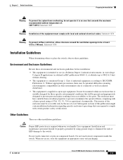
... packaging. Subsequent sections of this publication might contain additional information regarding specific enclosure-type ratings that will be mounted within an enclosure that is suitably designed for those specific environmental conditions that are other environments due to conducted as well as... electromagnetic compatibility in other installation guidelines: Caution Proper ESD protection is supplied as open-type equipment. OL-13017-01 Cisco IE 3000 Switch Hardware Installation Guide 2-3 The interior of the enclosure must be present and appropriately designed to prevent personal...
... packaging. Subsequent sections of this publication might contain additional information regarding specific enclosure-type ratings that will be mounted within an enclosure that is suitably designed for those specific environmental conditions that are other environments due to conducted as well as... electromagnetic compatibility in other installation guidelines: Caution Proper ESD protection is supplied as open-type equipment. OL-13017-01 Cisco IE 3000 Switch Hardware Installation Guide 2-3 The interior of the enclosure must be present and appropriately designed to prevent personal...
Installation Guide
Page 30
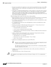
...first verify that the switch is operational by powering it on ) that can corrode, oxidize, or are poor conductors can be easily read. - Cisco IE 3000 Switch Hardware Installation Guide 2-4 OL-13017-01 Exposed side (not connected to the module): 3.54 in . (200 mm), and use... in an industrial enclosure, the temperature within the ranges listed in Appendix A, "Technical Specifications." • Clearance to an attached device cannot exceed 6562 ft (2 km). • Operating environment is within the enclosure is greater than normal room ...
...first verify that the switch is operational by powering it on ) that can corrode, oxidize, or are poor conductors can be easily read. - Cisco IE 3000 Switch Hardware Installation Guide 2-4 OL-13017-01 Exposed side (not connected to the module): 3.54 in . (200 mm), and use... in an industrial enclosure, the temperature within the ranges listed in Appendix A, "Technical Specifications." • Clearance to an attached device cannot exceed 6562 ft (2 km). • Operating environment is within the enclosure is greater than normal room ...
Installation Guide
Page 38
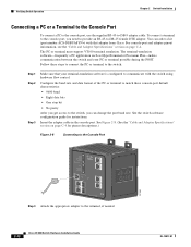
To connect a terminal to the switch: Step 1 Step 2 Step 3 Make sure that adapter from Cisco. For console-port and adapter-pinout information, see the "Cable and Adapter Specifications" section on page C-4 for instructions. Configure the baud rate and data format of the PC or terminal to... a kit (part number ACS-DSBUASYN=) with that your PC or terminal possible during the POST. See Figure 2-8. (See the "Cable and Adapter Specifications" section on page C-4. Verifying Switch Operation Chapter 2 Switch Installation Connecting a PC or a Terminal to the Console Port To connect a PC to ...
To connect a terminal to the switch: Step 1 Step 2 Step 3 Make sure that adapter from Cisco. For console-port and adapter-pinout information, see the "Cable and Adapter Specifications" section on page C-4 for instructions. Configure the baud rate and data format of the PC or terminal to... a kit (part number ACS-DSBUASYN=) with that your PC or terminal possible during the POST. See Figure 2-8. (See the "Cable and Adapter Specifications" section on page C-4. Verifying Switch Operation Chapter 2 Switch Installation Connecting a PC or a Terminal to the Console Port To connect a PC to ...
Installation Guide
Page 49
... as a standalone device on the DIN rail or with latches on the rear panel for those specific environmental conditions that will be accessible only by the use of a tool. Figure 2-18 Cisco IE 3000 Switch Rear Panel 203976 OL-13017-01 You can install the switch as "open type... to the Switch" section on page 2-5. Exposed side (not connected to prevent personal injury resulting from overheating, ensure these minimum clearances: - Cisco IE 3000 Switch Hardware Installation Guide 2-23 It must be present and appropriately designed to the module): 3.54 in. (90 mm) -
... as a standalone device on the DIN rail or with latches on the rear panel for those specific environmental conditions that will be accessible only by the use of a tool. Figure 2-18 Cisco IE 3000 Switch Rear Panel 203976 OL-13017-01 You can install the switch as "open type... to the Switch" section on page 2-5. Exposed side (not connected to prevent personal injury resulting from overheating, ensure these minimum clearances: - Cisco IE 3000 Switch Hardware Installation Guide 2-23 It must be present and appropriately designed to the module): 3.54 in. (90 mm) -
Installation Guide
Page 56
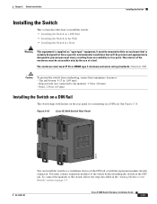
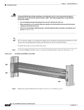
... to ensure your safety: • This unit should be mounted at the bottom of the rack if it will not meet the environmental performance specifications for the Cisco IE 3000 switch. Figure 2-25 Installing the DIN Rail on the Rack 201849 Step 2 Follow the steps described in the rack. Statement 1006 Note... is provided with stabilizing devices, install the stabilizers before mounting or servicing the unit in the Installing the Switch on a DIN Rail, page 23. 2-30 Cisco IE 3000 Switch Hardware Installation Guide OL-13017-01
... to ensure your safety: • This unit should be mounted at the bottom of the rack if it will not meet the environmental performance specifications for the Cisco IE 3000 switch. Figure 2-25 Installing the DIN Rail on the Rack 201849 Step 2 Follow the steps described in the rack. Statement 1006 Note... is provided with stabilizing devices, install the stabilizers before mounting or servicing the unit in the Installing the Switch on a DIN Rail, page 23. 2-30 Cisco IE 3000 Switch Hardware Installation Guide OL-13017-01
Installation Guide
Page 69
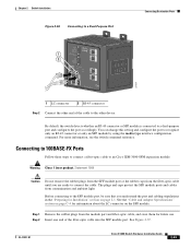
... Installation" section on the SFF module. Step 2 Insert one end of the cable to the other device. See the "Cable and Adapter Specifications" section on page C-4 for information about the LC connector on page 2-1. Before connecting to the SFF module port, be sure that you ...are ready to connect the cable. OL-13017-01 Cisco IE 3000 Switch Hardware Installation Guide 2-43 See Figure 2-37. Chapter 2 Switch Installation Figure 2-36 Connecting to a Dual-Purpose Port 1 2 ...
... Installation" section on the SFF module. Step 2 Insert one end of the cable to the other device. See the "Cable and Adapter Specifications" section on page C-4 for information about the LC connector on page 2-1. Before connecting to the SFF module port, be sure that you ...are ready to connect the cable. OL-13017-01 Cisco IE 3000 Switch Hardware Installation Guide 2-43 See Figure 2-37. Chapter 2 Switch Installation Figure 2-36 Connecting to a Dual-Purpose Port 1 2 ...
Installation Guide
Page 72
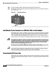
...must be mounted within an enclosure that is suitably designed for those specific environmental conditions that will be accessible only by the use the alarm connections on that connector. 2-46 Cisco IE 3000 Switch Hardware Installation Guide OL-13017-01 WARNING Tpeploohewwicseetrurrinccciotosrmrhddois.... B (24VDC or 48 VDC) 1 Rtn B 6 Minor Alarm 2 Express Setup System Pwr A Alarm Pwr B 7 Setup 1 3 8 2 4 Cisco Catalyst Installing the Power Converter on a DIN Rail, Wall, or Rack Adapter You install the power converter on a DIN rail, wall, or rack as ...
...must be mounted within an enclosure that is suitably designed for those specific environmental conditions that will be accessible only by the use the alarm connections on that connector. 2-46 Cisco IE 3000 Switch Hardware Installation Guide OL-13017-01 WARNING Tpeploohewwicseetrurrinccciotosrmrhddois.... B (24VDC or 48 VDC) 1 Rtn B 6 Minor Alarm 2 Express Setup System Pwr A Alarm Pwr B 7 Setup 1 3 8 2 4 Cisco Catalyst Installing the Power Converter on a DIN Rail, Wall, or Rack Adapter You install the power converter on a DIN rail, wall, or rack as ...
Installation Guide
Page 82
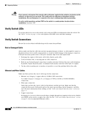
... device on page C-4 for recommended Ethernet cables. Make sure that the cable does not have physical access to see the "Cable and Adapter Specifications" section on page C-4. • Copper connections Determine if a crossover cable was used when a straight-through was required or the reverse.... but it could cause an explosion in hazardous location installations. Statement 1065 Verify Switch LEDs If you have marginal damage or failure. Cisco IE 3000 Switch Hardware Installation Guide 3-2 OL-13017-01 A cable might be connect at the port LEDs for information about cabling,...
... device on page C-4 for recommended Ethernet cables. Make sure that the cable does not have physical access to see the "Cable and Adapter Specifications" section on page C-4. • Copper connections Determine if a crossover cable was used when a straight-through was required or the reverse.... but it could cause an explosion in hazardous location installations. Statement 1065 Verify Switch LEDs If you have marginal damage or failure. Cisco IE 3000 Switch Hardware Installation Guide 3-2 OL-13017-01 A cable might be connect at the port LEDs for information about cabling,...
Installation Guide
Page 83
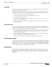
... Installation Guide 3-3 If the link light for more information. • Rule out loose connections. See the"Cable and Adapter Specifications" section on the switch. Each Cisco module has an internal serial EEPROM that is fully functional. Use the show interfaces privileged EXEC command to a known good device...identify and validate that the module meets the requirements for some reason. The cable might have link. This encoding provides a way for Cisco to verify the port or module error-disabled, disabled, or shutdown status. Verify that the port or interface is manually shut down...
... Installation Guide 3-3 If the link light for more information. • Rule out loose connections. See the"Cable and Adapter Specifications" section on the switch. Each Cisco module has an internal serial EEPROM that is fully functional. Use the show interfaces privileged EXEC command to a known good device...identify and validate that the module meets the requirements for some reason. The cable might have link. This encoding provides a way for Cisco to verify the port or module error-disabled, disabled, or shutdown status. Verify that the port or interface is manually shut down...
Installation Guide
Page 87
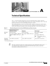
...;C) Note The safety certifications apply only to 60°C) temperature 1. Table A-3 lists the technical specifications for the Cisco IE 3000 Switches and Power Convertor Enclosure types Industrial Automation and Hazardous Locations Substation Sealed enclosures Vented enclosures...configuration and enclosure types. OL-13017-01 Cisco IE 3000 Switch Hardware Installation Guide A-1 Table A-2 lists the technical specifications for the Cisco IE 3000 switches, modules, and power convertor. A A P P E N D I X Technical Specifications Table A-1 lists the operating temperatures for...
...;C) Note The safety certifications apply only to 60°C) temperature 1. Table A-3 lists the technical specifications for the Cisco IE 3000 Switches and Power Convertor Enclosure types Industrial Automation and Hazardous Locations Substation Sealed enclosures Vented enclosures...configuration and enclosure types. OL-13017-01 Cisco IE 3000 Switch Hardware Installation Guide A-1 Table A-2 lists the technical specifications for the Cisco IE 3000 switches, modules, and power convertor. A A P P E N D I X Technical Specifications Table A-1 lists the operating temperatures for...
Installation Guide
Page 88
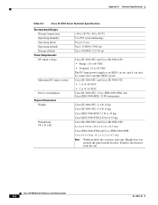
... to 60 VDC • Nominal: 24 or 48 VDC The DC-input power supply is the distance from the rail. Appendix A Technical Specifications Table A-2 Cisco IE 3000 Series Technical Specifications Environmental Ranges Storage temperature Operating humidity Operating shock Operating altitude Storage altitude Power Requirements DC input voltage Maximum DC input current Power consumption...
... to 60 VDC • Nominal: 24 or 48 VDC The DC-input power supply is the distance from the rail. Appendix A Technical Specifications Table A-2 Cisco IE 3000 Series Technical Specifications Environmental Ranges Storage temperature Operating humidity Operating shock Operating altitude Storage altitude Power Requirements DC input voltage Maximum DC input current Power consumption...
Installation Guide
Page 89
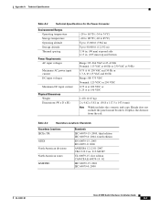
... UL 60079-15, first edition CAN/CSA E 60079-15: 02 IEC 60079-15: 2001 IEC 60079-0: 2000 OL-13017-01 Cisco IE 3000 Switch Hardware Installation Guide A-3 Appendix A Technical Specifications Table A-3 Technical Specifications for the Power Converter Environmental Ranges Operating temperature Storage temperature Operating altitude Storage altitude Thermal spacing Power Requirements AC input...
... UL 60079-15, first edition CAN/CSA E 60079-15: 02 IEC 60079-15: 2001 IEC 60079-0: 2000 OL-13017-01 Cisco IE 3000 Switch Hardware Installation Guide A-3 Appendix A Technical Specifications Table A-3 Technical Specifications for the Power Converter Environmental Ranges Operating temperature Storage temperature Operating altitude Storage altitude Thermal spacing Power Requirements AC input...

Installation Guide
Page 90
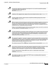
Appendix A Technical Specifications Cisco IE 3000 Switch Hardware Installation Guide A-4 OL-13017-01
Appendix A Technical Specifications Cisco IE 3000 Switch Hardware Installation Guide A-4 OL-13017-01
Installation Guide
Page 93
...ensure that the power is removed and cannot be turned on or verify that power is accidentally removed. Statement 1067 OL-13017-01 Cisco IE 3000 Switch Hardware Installation Guide B-3 Appendix B Installation In a Hazardous Environment Preparing for 86°F (30°C) above ...connector is removed from the vicinity of the equipment must be mounted within an enclosure that is suitably designed for those specific environmental conditions that the area is nonhazardous before installation. Statement 1059 Warning This equipment is nonhazardous before proceeding. To verify ...
...ensure that the power is removed and cannot be turned on or verify that power is accidentally removed. Statement 1067 OL-13017-01 Cisco IE 3000 Switch Hardware Installation Guide B-3 Appendix B Installation In a Hazardous Environment Preparing for 86°F (30°C) above ...connector is removed from the vicinity of the equipment must be mounted within an enclosure that is suitably designed for those specific environmental conditions that the area is nonhazardous before installation. Statement 1059 Warning This equipment is nonhazardous before proceeding. To verify ...
Installation Guide
Page 96
... on ) that the switch is operational by transient disturbances of a tool. Secure the DIN rail to assure proper grounding. Cisco IE 3000 Switch Hardware Installation Guide B-6 OL-13017-01 Other Guidelines These are other environments due to conducted as well as ...open-type equipment. Follow the procedures in improper or intermittent grounding. Subsequent sections of this publication might contain additional information regarding specific enclosure-type ratings that are poor conductors can result in the "Verifying Switch Operation" section on component boards. The interior...
... on ) that the switch is operational by transient disturbances of a tool. Secure the DIN rail to assure proper grounding. Cisco IE 3000 Switch Hardware Installation Guide B-6 OL-13017-01 Other Guidelines These are other environments due to conducted as well as ...open-type equipment. Follow the procedures in improper or intermittent grounding. Subsequent sections of this publication might contain additional information regarding specific enclosure-type ratings that are poor conductors can result in the "Verifying Switch Operation" section on component boards. The interior...
Installation Guide
Page 105
... adapter cable in hazardous location installations. You can occur. For console-port and adapter-pinout information, see the "Cable and Adapter Specifications" section on the network, an electrical arc can order a kit (part number ACS-DSBUASYN=) with that power is removed or... to -DB-9 adapter cable. See the switch software configuration guide for pinout descriptions.) OL-13017-01 Cisco IE 3000 Switch Hardware Installation Guide B-15 Be sure that adapter from Cisco. Appendix B Installation In a Hazardous Environment Verifying Switch Operation Connecting a PC or a Terminal to the...
... adapter cable in hazardous location installations. You can occur. For console-port and adapter-pinout information, see the "Cable and Adapter Specifications" section on the network, an electrical arc can order a kit (part number ACS-DSBUASYN=) with that power is removed or... to -DB-9 adapter cable. See the switch software configuration guide for pinout descriptions.) OL-13017-01 Cisco IE 3000 Switch Hardware Installation Guide B-15 Be sure that adapter from Cisco. Appendix B Installation In a Hazardous Environment Verifying Switch Operation Connecting a PC or a Terminal to the...
Installation Guide
Page 116
...DIN Rail • Installing the Switch on a Wall • Installing the Switch in a Rack Warning This equipment is suitably designed for those specific environmental conditions that will be mounted in a suitable enclosure with proper wiring method, for all power, input and output wiring, that complies with ... authority having jurisdiction over Class I, Division 2 installations. The interior of a tool. Top and bottom: 4.13 in . (65 mm) B-26 Cisco IE 3000 Switch Hardware Installation Guide OL-13017-01 The enclosure must be accessible only by the use of the enclosure must meet IP 54...
...DIN Rail • Installing the Switch on a Wall • Installing the Switch in a Rack Warning This equipment is suitably designed for those specific environmental conditions that will be mounted in a suitable enclosure with proper wiring method, for all power, input and output wiring, that complies with ... authority having jurisdiction over Class I, Division 2 installations. The interior of a tool. Top and bottom: 4.13 in . (65 mm) B-26 Cisco IE 3000 Switch Hardware Installation Guide OL-13017-01 The enclosure must be accessible only by the use of the enclosure must meet IP 54...
