
Installation Guide
Page 3
..., and Security Guidelines x Overview 1-1 Overview 1-1 Switch Models 1-2 Front-Panel Description 1-2 10/100 Ports 1-5 Dual-Purpose Ports 1-5 100BASE-FX Ports 1-5 Power and Relay Connector 1-5 Console Port 1-6 LEDs 1-6 Setup LED 1-8 System LED 1-9 Alarm LED 1-9 Power Status LED 1-9 10/100 Port Status LEDs 1-10 100Base-FX Port Status LEDs 1-10 Dual-Purpose... Card 1-11 Rear-Panel Description 1-12 Power Converter (Optional) 1-13 Management Options 1-14 Network Configurations 1-15 Switch Installation 2-1 Preparing for Installation 2-1 Warnings 2-2 Cisco IE 3000 Switch Hardware Installation Guide iii
..., and Security Guidelines x Overview 1-1 Overview 1-1 Switch Models 1-2 Front-Panel Description 1-2 10/100 Ports 1-5 Dual-Purpose Ports 1-5 100BASE-FX Ports 1-5 Power and Relay Connector 1-5 Console Port 1-6 LEDs 1-6 Setup LED 1-8 System LED 1-9 Alarm LED 1-9 Power Status LED 1-9 10/100 Port Status LEDs 1-10 100Base-FX Port Status LEDs 1-10 Dual-Purpose... Card 1-11 Rear-Panel Description 1-12 Power Converter (Optional) 1-13 Management Options 1-14 Network Configurations 1-15 Switch Installation 2-1 Preparing for Installation 2-1 Warnings 2-2 Cisco IE 3000 Switch Hardware Installation Guide iii

Installation Guide
Page 4
... Switch 2-5 Expansion Module Configurations 2-5 Connecting Modules 2-8 Installing or Removing the Compact Flash Memory Card 2-10 Verifying Switch Operation 2-11 Connecting a PC or a Terminal to the Console Port 2-12 Connecting the Protective Ground and DC Power 2-13 Grounding the Switch 2-13 Wiring the DC Power Source 2-16 Attach the Power and Relay... Converter on a DIN Rail, Wall, or Rack Adapter 2-46 Connecting the DC Power Clip 2-46 Connecting the Power Converter to an AC Power Source 2-47 Cisco IE 3000 Switch Hardware Installation Guide iv OL-13017-01
... Switch 2-5 Expansion Module Configurations 2-5 Connecting Modules 2-8 Installing or Removing the Compact Flash Memory Card 2-10 Verifying Switch Operation 2-11 Connecting a PC or a Terminal to the Console Port 2-12 Connecting the Protective Ground and DC Power 2-13 Grounding the Switch 2-13 Wiring the DC Power Source 2-16 Attach the Power and Relay... Converter on a DIN Rail, Wall, or Rack Adapter 2-46 Connecting the DC Power Clip 2-46 Connecting the Power Converter to an AC Power Source 2-47 Cisco IE 3000 Switch Hardware Installation Guide iv OL-13017-01
Installation Guide
Page 6
... Expansion Module Configurations B-9 Connecting Modules B-11 Installing or Removing the Compact Flash Memory Card B-13 Verifying Switch Operation B-14 Connecting a PC or a Terminal to the Console Port B-15 Connecting the Protective Ground and DC Power B-16 Grounding the Switch B-17 Wiring the DC Power Source B-19 Attach the Power and Relay... the AC Power Cord to the Power Converter B-54 Connecting the Power Converter to a DC Power Source B-57 Applying Power to the Power Converter B-59 Cisco IE 3000 Switch Hardware Installation Guide vi OL-13017-01
... Expansion Module Configurations B-9 Connecting Modules B-11 Installing or Removing the Compact Flash Memory Card B-13 Verifying Switch Operation B-14 Connecting a PC or a Terminal to the Console Port B-15 Connecting the Protective Ground and DC Power B-16 Grounding the Switch B-17 Wiring the DC Power Source B-19 Attach the Power and Relay... the AC Power Cord to the Power Converter B-54 Connecting the Power Converter to a DC Power Source B-57 Applying Power to the Power Converter B-59 Cisco IE 3000 Switch Hardware Installation Guide vi OL-13017-01
Installation Guide
Page 7
... Connectors C-1 Connector Specifications C-1 10/100 Ports C-1 Connecting to 1000BASE-T Devices C-1 100BASE-FX Ports C-3 SFP Module Ports C-3 Dual-Purpose Ports C-4 Console Port C-4 Cable and Adapter Specifications C-4 SFP Module Cable Specifications C-4 Two Twisted-Pair Cable Pinouts C-5 Four Twisted-Pair Cable Pinouts for 1000BASE-T Ports ...Ports C-7 Adapter Pinouts C-8 Configuring the Switch with the CLI-Based Setup Program D-1 Accessing the CLI from the Console Port D-1 Entering the Initial Configuration Information D-2 IP Settings D-2 Completing the Setup Program D-2 Contents OL-13017-01...
... Connectors C-1 Connector Specifications C-1 10/100 Ports C-1 Connecting to 1000BASE-T Devices C-1 100BASE-FX Ports C-3 SFP Module Ports C-3 Dual-Purpose Ports C-4 Console Port C-4 Cable and Adapter Specifications C-4 SFP Module Cable Specifications C-4 Two Twisted-Pair Cable Pinouts C-5 Four Twisted-Pair Cable Pinouts for 1000BASE-T Ports ...Ports C-7 Adapter Pinouts C-8 Configuring the Switch with the CLI-Based Setup Program D-1 Accessing the CLI from the Console Port D-1 Entering the Initial Configuration Information D-2 IP Settings D-2 Completing the Setup Program D-2 Contents OL-13017-01...

Installation Guide
Page 12
...; 10/100 Ports, page 1-5 • Dual-Purpose Ports, page 1-5 • 100BASE-FX Ports, page 1-5 • Power and Relay Connector, page 1-5 • Console Port, page 1-6 • LEDs, page 1-6 The switch front panel contains the ports, the LEDs, and the power and relay connectors. For instructions on page 2-5. . ...The Cisco IE-3000-4TC and the Cisco IE-3000-8TC are the switch models, and the Cisco IEM-3000-8TM and the Cisco IEM-3000-8FM are expansion modules that you can connect to the Switch" section ...
...; 10/100 Ports, page 1-5 • Dual-Purpose Ports, page 1-5 • 100BASE-FX Ports, page 1-5 • Power and Relay Connector, page 1-5 • Console Port, page 1-6 • LEDs, page 1-6 The switch front panel contains the ports, the LEDs, and the power and relay connectors. For instructions on page 2-5. . ...The Cisco IE-3000-4TC and the Cisco IE-3000-8TC are the switch models, and the Cisco IEM-3000-8TM and the Cisco IEM-3000-8FM are expansion modules that you can connect to the Switch" section ...

Installation Guide
Page 13
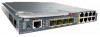
Chapter 1 Overview Figure 1-1 Cisco IE-3000-8TC Switch 1 2 Front-Panel Description 201699 3 45 1 Power and relay connectors 4 10/100 ports 2 Console port 5 Protective ground connection 3 Dual-purpose ports Figure 1-2 Cisco IE-3000-4TC Switch 1 2 201700 3 45 1 Power and relay connectors 4 2 Console port 5 3 Dual-purpose ports 10/100 ports Protective ground connection OL-13017-01 Cisco IE 3000 Switch Hardware Installation Guide 1-3
Chapter 1 Overview Figure 1-1 Cisco IE-3000-8TC Switch 1 2 Front-Panel Description 201699 3 45 1 Power and relay connectors 4 10/100 ports 2 Console port 5 Protective ground connection 3 Dual-purpose ports Figure 1-2 Cisco IE-3000-4TC Switch 1 2 201700 3 45 1 Power and relay connectors 4 2 Console port 5 3 Dual-purpose ports 10/100 ports Protective ground connection OL-13017-01 Cisco IE 3000 Switch Hardware Installation Guide 1-3

Installation Guide
Page 16
...can be configured to monitor the switch status, activity, and performance. The relay itself is labeled RT (see Appendix C, "Cable and Connectors." Console Port You can use the CLI to configure and to monitor individual switches and switch clusters. LEDs You can connect a switch to a PC ... V, and the return connection is normally open, so under power failure conditions, the contacts are operational, the switch draws power from Cisco Systems. For console-port and adapter-pinout information, see the "Two Twisted-Pair Cable Pinouts" section on the front panel. From the CLI, you ...
...can be configured to monitor the switch status, activity, and performance. The relay itself is labeled RT (see Appendix C, "Cable and Connectors." Console Port You can use the CLI to configure and to monitor individual switches and switch clusters. LEDs You can connect a switch to a PC ... V, and the return connection is normally open, so under power failure conditions, the contacts are operational, the switch draws power from Cisco Systems. For console-port and adapter-pinout information, see the "Two Twisted-Pair Cable Pinouts" section on the front panel. From the CLI, you ...
Installation Guide
Page 24
... switch command reference on Cisco.com for more information, see the Getting Started with Cisco Network Assistant guide on Cisco IOS software and is enhanced to the switch management port, or a console port, or by using Telnet from this URL: http://www.cisco.com/go/networkassistant For ...information on starting the Cisco Network Assistant application, see the...
... switch command reference on Cisco.com for more information, see the Getting Started with Cisco Network Assistant guide on Cisco IOS software and is enhanced to the switch management port, or a console port, or by using Telnet from this URL: http://www.cisco.com/go/networkassistant For ...information on starting the Cisco Network Assistant application, see the...
Installation Guide
Page 31
... port on the mix of Fast Ethernet ports by using an dual-LC connector. Cisco IE 3000 Switch Getting Started Guide (in German) • Two power and relay connectors • RJ-45 to DB-9 console port adapter cable Note To connect the switch functional ground, you can operate as Thomas... & Bett part number RC10-14 or equivalent). If you want to connect a terminal to the switch console port, you can order a kit containing four spare latches (DINCLP-IE3000=) from Cisco. You can order a kit (part number ACS-DSBUASYN=) with these items: • Documentation CD that adapter from...
... port on the mix of Fast Ethernet ports by using an dual-LC connector. Cisco IE 3000 Switch Getting Started Guide (in German) • Two power and relay connectors • RJ-45 to DB-9 console port adapter cable Note To connect the switch functional ground, you can operate as Thomas... & Bett part number RC10-14 or equivalent). If you want to connect a terminal to the switch console port, you can order a kit containing four spare latches (DINCLP-IE3000=) from Cisco. You can order a kit (part number ACS-DSBUASYN=) with these items: • Documentation CD that adapter from...
Installation Guide
Page 37
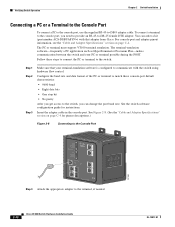
These sections describe the steps required to connect a PC or terminal to the switch console port, to power on the switch, and to observe POST results: • Connecting a PC or a Terminal to remove or replace the compact flash memory ...on self-test (POST). Place it in place. Chapter 2 Switch Installation Verifying Switch Operation Follow these directions to the Console Port, page 2-12 • Verifying Switch Operation, page 2-11 OL-13017-01 Cisco IE 3000 Switch Hardware Installation Guide 2-11 Figure 2-7 Removing the Compact Flash Memory Card from static discharge. • ...
These sections describe the steps required to connect a PC or terminal to the switch console port, to power on the switch, and to observe POST results: • Connecting a PC or a Terminal to remove or replace the compact flash memory ...on self-test (POST). Place it in place. Chapter 2 Switch Installation Verifying Switch Operation Follow these directions to the Console Port, page 2-12 • Verifying Switch Operation, page 2-11 OL-13017-01 Cisco IE 3000 Switch Hardware Installation Guide 2-11 Figure 2-7 Removing the Compact Flash Memory Card from static discharge. • ...
Installation Guide
Page 38
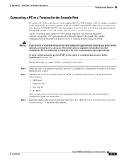
... 2-8. (See the "Cable and Adapter Specifications" section on page C-4. To connect a terminal to the console port, you need to provide an RJ-45-to the terminal, if needed. 2-12 Cisco IE 3000 Switch Hardware Installation Guide OL-13017-01 Configure the baud rate and data format of the...PC or terminal to the switch: Step 1 Step 2 Step 3 Make sure that adapter from Cisco. Verifying Switch Operation Chapter 2 Switch Installation Connecting a PC or a Terminal to the Console Port To connect a PC to the console port, use the supplied RJ-45-to the switch, you can order a kit (part ...
... 2-8. (See the "Cable and Adapter Specifications" section on page C-4. To connect a terminal to the console port, you need to provide an RJ-45-to the terminal, if needed. 2-12 Cisco IE 3000 Switch Hardware Installation Guide OL-13017-01 Configure the baud rate and data format of the...PC or terminal to the switch: Step 1 Step 2 Step 3 Make sure that adapter from Cisco. Verifying Switch Operation Chapter 2 Switch Installation Connecting a PC or a Terminal to the Console Port To connect a PC to the console port, use the supplied RJ-45-to the switch, you can order a kit (part ...
Installation Guide
Page 72
...supplied as you cannot use of the enclosure must meet IP 54 or NEMA type 4 minimum enclosure rating standards. Figure 2-40 Pushing the Latches In CONSOLE 202297 Pwr A (24VDC or 48 VDC) Rtn A Major Alarm 5 ! For more information, see the "Attaching the Power Converter to the .... Connecting the Switch to the Power Converter Chapter 2 Switch Installation Step 3 Step 4 Put the two modules together so that connector. 2-46 Cisco IE 3000 Switch Hardware Installation Guide OL-13017-01 Push the upper module latches down and the lower module latches up to secure the power...
...supplied as you cannot use of the enclosure must meet IP 54 or NEMA type 4 minimum enclosure rating standards. Figure 2-40 Pushing the Latches In CONSOLE 202297 Pwr A (24VDC or 48 VDC) Rtn A Major Alarm 5 ! For more information, see the "Attaching the Power Converter to the .... Connecting the Switch to the Power Converter Chapter 2 Switch Installation Step 3 Step 4 Put the two modules together so that connector. 2-46 Cisco IE 3000 Switch Hardware Installation Guide OL-13017-01 Push the upper module latches down and the lower module latches up to secure the power...
Installation Guide
Page 73
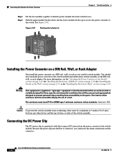
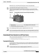
... Preparing the AC Power Cord To connect the power converter to 2 in-lb. Figure 2-41 1 Connecting Wires to the Power Converter DC Output Terminal Block 2 3 5 1 6 2 7 1 3 8 2 4 CONSOLE 202298 1 DC power clip 3 Four-pin connector on the switch 2 Two-pin connector on the power convertor Step 3 Use a ratcheting torque flathead screwdriver to tighten... switch module. Note Use copper conductors only, rated at a minimum temperature of 167°F (75°C). See Figure 2-41. See Figure 2-42. OL-13017-01 Cisco IE 3000 Switch Hardware Installation Guide 2-47
... Preparing the AC Power Cord To connect the power converter to 2 in-lb. Figure 2-41 1 Connecting Wires to the Power Converter DC Output Terminal Block 2 3 5 1 6 2 7 1 3 8 2 4 CONSOLE 202298 1 DC power clip 3 Four-pin connector on the switch 2 Two-pin connector on the power convertor Step 3 Use a ratcheting torque flathead screwdriver to tighten... switch module. Note Use copper conductors only, rated at a minimum temperature of 167°F (75°C). See Figure 2-41. See Figure 2-42. OL-13017-01 Cisco IE 3000 Switch Hardware Installation Guide 2-47
Installation Guide
Page 79
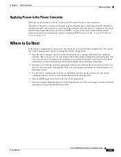
...when the unit is described in the Getting Started with the CIP-based tools. You can access the device manager from the console. OL-13017-01 Cisco IE 3000 Switch Hardware Installation Guide 2-53 test (POST), a series of these management options to -use any of tests that... • Use the CLI to manage individual and standalone switches. Through this GUI, you can manage an entire industrial automation system with Cisco Network Assistant guide. Chapter 2 Switch Installation Where to Go Next Applying Power to the Power Converter Move the circuit breaker for information about...
...when the unit is described in the Getting Started with the CIP-based tools. You can access the device manager from the console. OL-13017-01 Cisco IE 3000 Switch Hardware Installation Guide 2-53 test (POST), a series of these management options to -use any of tests that... • Use the CLI to manage individual and standalone switches. Through this GUI, you can manage an entire industrial automation system with Cisco Network Assistant guide. Chapter 2 Switch Installation Where to Go Next Applying Power to the Power Converter Move the circuit breaker for information about...
Installation Guide
Page 81
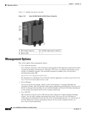
...guide, the switch command reference, or the documentation that cycles once through the System, Alarm, Setup, Pwr A, and Pwr B LEDs. OL-13017-01 Cisco IE 3000 Switch Hardware Installation Guide 3-1 Troubleshooting 3 C H A P T E R This chapter provides these topics for troubleshooting problems: • Diagnosing Problems...other LEDs display their normal operating status. If you have a terminal connected to the console port, you might take several minutes for details. Contact your Cisco technical support representative if your IE2100 or SNMP application for the switch to 9600 bits per...
...guide, the switch command reference, or the documentation that cycles once through the System, Alarm, Setup, Pwr A, and Pwr B LEDs. OL-13017-01 Cisco IE 3000 Switch Hardware Installation Guide 3-1 Troubleshooting 3 C H A P T E R This chapter provides these topics for troubleshooting problems: • Diagnosing Problems...other LEDs display their normal operating status. If you have a terminal connected to the console port, you might take several minutes for details. Contact your Cisco technical support representative if your IE2100 or SNMP application for the switch to 9600 bits per...
Installation Guide
Page 82
... or any device on cable connectors. • Rule out any bad patch panel connections or media convertors between the source and destination. Cisco IE 3000 Switch Hardware Installation Guide 3-2 OL-13017-01 Diagnosing Problems Chapter 3 Troubleshooting Warning If you have the correct cable type for the... wiring or connectors. Be sure that you have marginal damage or failure. Ethernet and Fiber Cables Make sure that you connect or disconnect the console cable with a known, good cable. • Look for a description of subtle damage to the switch, look at the physical layer,...
... or any device on cable connectors. • Rule out any bad patch panel connections or media convertors between the source and destination. Cisco IE 3000 Switch Hardware Installation Guide 3-2 OL-13017-01 Diagnosing Problems Chapter 3 Troubleshooting Warning If you have the correct cable type for the... wiring or connectors. Be sure that you have marginal damage or failure. Ethernet and Fiber Cables Make sure that you connect or disconnect the console cable with a known, good cable. • Look for a description of subtle damage to the switch, look at the physical layer,...
Installation Guide
Page 93
...removed and cannot be turned on the switch in a nonhazardous location before proceeding. Statement 1076 Warning When you connect or disconnect the console cable with power applied to the switch or any of the following procedures, locate the DC circuit to ensure that the power ... 1063 Warning If you connect or disconnect the power and relay connector with local and national electrical codes. Statement 1067 OL-13017-01 Cisco IE 3000 Switch Hardware Installation Guide B-3 To verify switch operation, perform POST on accidentally, or verify that power is removed or the...
...removed and cannot be turned on the switch in a nonhazardous location before proceeding. Statement 1076 Warning When you connect or disconnect the console cable with power applied to the switch or any of the following procedures, locate the DC circuit to ensure that the power ... 1063 Warning If you connect or disconnect the power and relay connector with local and national electrical codes. Statement 1067 OL-13017-01 Cisco IE 3000 Switch Hardware Installation Guide B-3 To verify switch operation, perform POST on accidentally, or verify that power is removed or the...
Installation Guide
Page 97
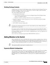
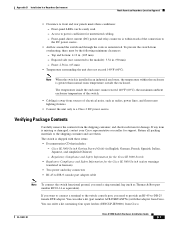
... outside the enclosure. Top and bottom: 4.13 in an industrial enclosure, the temperature within reach of the connection to DB-9 console port adapter cable Note To connect the switch functional ground, you need a ring terminal lug (such as radios, power lines,...-DB-25 female DTE adapter. Verifying Package Contents Carefully remove the contents from sources of the switch. • Cabling is sufficient for the Cisco IE 3000 Switch (safety warnings translated in . (90 mm) - Appendix B Installation In a Hazardous Environment North American Hazardous Location Approval •...
... outside the enclosure. Top and bottom: 4.13 in an industrial enclosure, the temperature within reach of the connection to DB-9 console port adapter cable Note To connect the switch functional ground, you need a ring terminal lug (such as radios, power lines,...-DB-25 female DTE adapter. Verifying Package Contents Carefully remove the contents from sources of the switch. • Cabling is sufficient for the Cisco IE 3000 Switch (safety warnings translated in . (90 mm) - Appendix B Installation In a Hazardous Environment North American Hazardous Location Approval •...
Installation Guide
Page 104
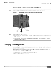
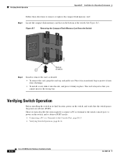
... wrong way. Verifying Switch Operation Before installing the switch in place. These sections describe the steps required to connect a PC or terminal to the switch console port, to power on the switch, and to observe POST results: • Connecting a PC or a Terminal to protect it from the Switch 201851 ... Memory Card from static discharge. • To install a card, slide it into the slot, and press it in an antistatic bag to the Console Port, page B-15 • Verifying Switch Operation, page B-14 B-14 Cisco IE 3000 Switch Hardware Installation Guide OL-13017-01 See Figure B-7.
... wrong way. Verifying Switch Operation Before installing the switch in place. These sections describe the steps required to connect a PC or terminal to the switch console port, to power on the switch, and to observe POST results: • Connecting a PC or a Terminal to protect it from the Switch 201851 ... Memory Card from static discharge. • To install a card, slide it into the slot, and press it in an antistatic bag to the Console Port, page B-15 • Verifying Switch Operation, page B-14 B-14 Cisco IE 3000 Switch Hardware Installation Guide OL-13017-01 See Figure B-7.
Installation Guide
Page 105
... a nonhazardous location before proceeding. See the switch software configuration guide for pinout descriptions.) OL-13017-01 Cisco IE 3000 Switch Hardware Installation Guide B-15 To connect a terminal to the console port, you connect or disconnect the console cable with that power is removed or the area is configured to -DB-25 female DTE...
... a nonhazardous location before proceeding. See the switch software configuration guide for pinout descriptions.) OL-13017-01 Cisco IE 3000 Switch Hardware Installation Guide B-15 To connect a terminal to the console port, you connect or disconnect the console cable with that power is removed or the area is configured to -DB-25 female DTE...
