
Hardware Maintenance Manual
Page 5
... This Manual xv Document Objectives xv Audience xv Document Organization xv Document Conventions xvi Chapter 1 Cisco 4000 Series Overview 1-1 External Differences in Models of the Cisco 4000 Series 1-1 Series Specifications 1-2 Memory Systems 1-4 Chapter 2 Preparing for Installation 2-1 Safety ... Auxiliary Port Connections 2-9 Network Connection Considerations 2-10 Ethernet Connections 2-10 Token Ring Connections 2-13 Serial Connections 2-15 Fiber Distributed Data Interface Connections 2-25 BRI Connections 2-29 Channelized T1 Connections 2-30 Channelized E1 Connections 2-32 ATM Connections ...
... This Manual xv Document Objectives xv Audience xv Document Organization xv Document Conventions xvi Chapter 1 Cisco 4000 Series Overview 1-1 External Differences in Models of the Cisco 4000 Series 1-1 Series Specifications 1-2 Memory Systems 1-4 Chapter 2 Preparing for Installation 2-1 Safety ... Auxiliary Port Connections 2-9 Network Connection Considerations 2-10 Ethernet Connections 2-10 Token Ring Connections 2-13 Serial Connections 2-15 Fiber Distributed Data Interface Connections 2-25 BRI Connections 2-29 Channelized T1 Connections 2-30 Channelized E1 Connections 2-32 ATM Connections ...

Hardware Maintenance Manual
Page 20
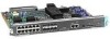
...module (NP-CT1) or with any two other types of the three available positions in any of network processor modules. The Cisco 4500-M and Cisco 4700 can be placed in any desired combination. For optimum heat dissipation, use the center slot position for the FDDI module... local memory • Hardware thermal alarm to three network processor modules at a time, including Ethernet, Token Ring, serial, single-mode and multimode Fiber Distributed Data Interface (FDDI), ISDN BRI, G.703, channelized T1/PRI, channelized T1/PRI, and ATM modules. Series Specifications Figure 1-1 shows the ...
...module (NP-CT1) or with any two other types of the three available positions in any of network processor modules. The Cisco 4500-M and Cisco 4700 can be placed in any desired combination. For optimum heat dissipation, use the center slot position for the FDDI module... local memory • Hardware thermal alarm to three network processor modules at a time, including Ethernet, Token Ring, serial, single-mode and multimode Fiber Distributed Data Interface (FDDI), ISDN BRI, G.703, channelized T1/PRI, channelized T1/PRI, and ATM modules. Series Specifications Figure 1-1 shows the ...

Hardware Maintenance Manual
Page 28
... the router: • ESD cord and wrist strap • Screwdrivers, Number 1 and Number 2 Phillips • One serial port adapter cable for multimode Fiber Distributed Data Interface (FDDI) connections. 2-6 Cisco 4000 Series Hardware Installation and Maintenance Site Log Site Log The Site Log provides a historical record of all actions relevant to reflect the...
... the router: • ESD cord and wrist strap • Screwdrivers, Number 1 and Number 2 Phillips • One serial port adapter cable for multimode Fiber Distributed Data Interface (FDDI) connections. 2-6 Cisco 4000 Series Hardware Installation and Maintenance Site Log Site Log The Site Log provides a historical record of all actions relevant to reflect the...

Hardware Maintenance Manual
Page 47
... Maximum Distance Between Stations Single-mode Up to 6 miles (10 kilometers) Multimode Up to 6 miles (10 kilometers). Network Connection Considerations Fiber Distributed Data Interface Connections Multimode FDDI network processor modules provide either a dual-attachment station (DAS) or a single-attachment station (SAS)....RING OP PHY-A RING OP AVOID EXPOSURE-INVISIBLE LASER RADIATION IS EMITTED FROM THESE APERTURES. 1300 NM CLASS 1 LASER PRODUCT LASERKLASSE 1 CISCO SYSTEMS, INC. 170 WEST TASMAN DRIVE SAN JOSE, CA 95134-1706 DATE: "Complies with one card fitting on the module's top...
... Maximum Distance Between Stations Single-mode Up to 6 miles (10 kilometers) Multimode Up to 6 miles (10 kilometers). Network Connection Considerations Fiber Distributed Data Interface Connections Multimode FDDI network processor modules provide either a dual-attachment station (DAS) or a single-attachment station (SAS)....RING OP PHY-A RING OP AVOID EXPOSURE-INVISIBLE LASER RADIATION IS EMITTED FROM THESE APERTURES. 1300 NM CLASS 1 LASER PRODUCT LASERKLASSE 1 CISCO SYSTEMS, INC. 170 WEST TASMAN DRIVE SAN JOSE, CA 95134-1706 DATE: "Complies with one card fitting on the module's top...

Hardware Maintenance Manual
Page 48
...Connector, MIC Type A dual-attachment module configuration requires two connections: one to the primary ring and one to FDDI standard 62.5/125 micron multimode fiber-optic cable. The PHY-A port is the bottom port (see Figure 2-24 and Figure 2-27), and PHY-B is connected. This product ... the Class 1 Laser Emission Requirement from the aperture ports of the single-mode FDDI products when no fiber cable is the top port on the other DAS. 2-26 Cisco 4000 Series Hardware Installation and Maintenance H1349a The multimode network processor module connectors are FDDI-standard physical sublayer ...
...Connector, MIC Type A dual-attachment module configuration requires two connections: one to the primary ring and one to FDDI standard 62.5/125 micron multimode fiber-optic cable. The PHY-A port is the bottom port (see Figure 2-24 and Figure 2-27), and PHY-B is connected. This product ... the Class 1 Laser Emission Requirement from the aperture ports of the single-mode FDDI products when no fiber cable is the top port on the other DAS. 2-26 Cisco 4000 Series Hardware Installation and Maintenance H1349a The multimode network processor module connectors are FDDI-standard physical sublayer ...

Hardware Maintenance Manual
Page 56
...ATM interface cable and accessories to the following physical layers: • SONET/SDH 155 Mbps multimode fiber optical-STS-3c or STM-1 (See Figure 2-41) • SONET/SDH 155 Mbps single-mode fiber optical-STS-3c or STM-1 (See Figure 2-40) All ATM interfaces are full-duplex. ... module supports PLIMs that connect to connect the ATM processor module with RJ-45 Connector) H2422 ATM Connections The ATM processor module for a Cisco 4000 series router provides a user network interface (UNI) between the router and an ATM network. Network Connection Considerations Figure 2-37 E1 Interface...
...ATM interface cable and accessories to the following physical layers: • SONET/SDH 155 Mbps multimode fiber optical-STS-3c or STM-1 (See Figure 2-41) • SONET/SDH 155 Mbps single-mode fiber optical-STS-3c or STM-1 (See Figure 2-40) All ATM interfaces are full-duplex. ... module supports PLIMs that connect to connect the ATM processor module with RJ-45 Connector) H2422 ATM Connections The ATM processor module for a Cisco 4000 series router provides a user network interface (UNI) between the router and an ATM network. Network Connection Considerations Figure 2-37 E1 Interface...

Hardware Maintenance Manual
Page 57
Therefore the Cisco 4500-M and Cisco 4700 routers currently support one ATM module. or multi-mode SONET connections, connect the fiber cable to be dropped. TASMAN DRIVE SAN JOSE CA. 95134 DATE: ÒComplies with FDA Radiation Performance Standards, 21 CFR, Subchapter JÓ H3157 ... RCVR RX CELLS RX ALARM WARNING AVOID EXPOSUREÐINVISIBLE LASER RADIATION IS EMITTED FROM THESE APERTURES. 1300 NM CLASS 1 LASER PRODUCT LASERKLASSE 1 CISCO SYSTEMS, INC. 170 W. ATM Cabling For single- Preparing for Installation 2-35 Remove the plug by pulling on the module front panel.
Therefore the Cisco 4500-M and Cisco 4700 routers currently support one ATM module. or multi-mode SONET connections, connect the fiber cable to be dropped. TASMAN DRIVE SAN JOSE CA. 95134 DATE: ÒComplies with FDA Radiation Performance Standards, 21 CFR, Subchapter JÓ H3157 ... RCVR RX CELLS RX ALARM WARNING AVOID EXPOSUREÐINVISIBLE LASER RADIATION IS EMITTED FROM THESE APERTURES. 1300 NM CLASS 1 LASER PRODUCT LASERKLASSE 1 CISCO SYSTEMS, INC. 170 W. ATM Cabling For single- Preparing for Installation 2-35 Remove the plug by pulling on the module front panel.

Hardware Maintenance Manual
Page 58
... meets the Class 1 Laser Emission Requirement from the aperture ports of the single-mode ATM products when no fiber-optic cable is not ready, keep the chassis in the Warranty Package). 2-36 Cisco 4000 Series Hardware Installation and Maintenance After determining where you encounter problems when installing or configuring your Product Registration... to ensure that you received all items for single mode and multi-mode SONET connections. Inspecting the System Note The ATM processor module for the Cisco 4000 series router uses identical duplex SC connectors for shipping damage.
... meets the Class 1 Laser Emission Requirement from the aperture ports of the single-mode ATM products when no fiber-optic cable is not ready, keep the chassis in the Warranty Package). 2-36 Cisco 4000 Series Hardware Installation and Maintenance After determining where you encounter problems when installing or configuring your Product Registration... to ensure that you received all items for single mode and multi-mode SONET connections. Inspecting the System Note The ATM processor module for the Cisco 4000 series router uses identical duplex SC connectors for shipping damage.
Hardware Maintenance Manual
Page 69
... supply before removing any doubt as to how to PHY-B on the FDDI module (the bottom port) to safely install the Cisco Systems BRI module correctly within the rating of the host chassis power supply. Ensure that attachments at the interconnection ports of the... station (DAS), connect PHY-A on the other DAS using a multimode fiber-optic cable. (See Figure 3-10.) Installing the Router 3-11 If you have any covers. Always disconnect the host chassis from a qualified telecommunications engineer. Additional Safety Information The BRI network processor modules contain safety extra-low ...
... supply before removing any doubt as to how to PHY-B on the FDDI module (the bottom port) to safely install the Cisco Systems BRI module correctly within the rating of the host chassis power supply. Ensure that attachments at the interconnection ports of the... station (DAS), connect PHY-A on the other DAS using a multimode fiber-optic cable. (See Figure 3-10.) Installing the Router 3-11 If you have any covers. Always disconnect the host chassis from a qualified telecommunications engineer. Additional Safety Information The BRI network processor modules contain safety extra-low ...

Hardware Maintenance Manual
Page 70
... network connections are complete, proceed to the section "Connecting to an Optical Bypass Switch" later in this chapter. 3-12 Cisco 4000 Series Hardware Installation and Maintenance Single-Attachment FDDI Connections Step 1 Using a multimode fiber-optic cable, connect the single-attachment module's PHY-S port through a concentrator to a single-attachment ring, or connect it...
... network connections are complete, proceed to the section "Connecting to an Optical Bypass Switch" later in this chapter. 3-12 Cisco 4000 Series Hardware Installation and Maintenance Single-Attachment FDDI Connections Step 1 Using a multimode fiber-optic cable, connect the single-attachment module's PHY-S port through a concentrator to a single-attachment ring, or connect it...

Hardware Maintenance Manual
Page 98
...chassis shell. Removing Network Processor Modules If you are mounted to the rear of the chassis with external rear mounting screws, which include the Fiber Distributed Data Interface (FDDI) module, these screws must first remove the network processor modules. On modules with two external screws. Follow the ... processor module, and the two external rear mounting screws (not shown) if the module has them, and set the screws aside. 5-4 Cisco 4000 Series Hardware Installation and Maintenance Step 1 With the component tray in front of you must be removed before the module can be safely...
...chassis shell. Removing Network Processor Modules If you are mounted to the rear of the chassis with external rear mounting screws, which include the Fiber Distributed Data Interface (FDDI) module, these screws must first remove the network processor modules. On modules with two external screws. Follow the ... processor module, and the two external rear mounting screws (not shown) if the module has them, and set the screws aside. 5-4 Cisco 4000 Series Hardware Installation and Maintenance Step 1 With the component tray in front of you must be removed before the module can be safely...

Hardware Maintenance Manual
Page 137
...b command (boot) C-2 Basic Rate Interface See BRI boot command D-3 boot ROMs, replacing 5-19 booting from Flash B-6 from the ROM monitor Cisco 4000-M C-2 Cisco 4500-M D-3 Cisco 4700 D-3 bootstrap clear memory contents C-2 stack trace, system software C-2 Break key (interrupt) C-1, D-1 BRI distance limitations 2-30, 3-6 making...35, four-port A-11 X.21, dual-port A-14 X.21, four-port A-15 serial, preparing to connect 2-21 single-mode fiber optic 2-25 specifications A-1 Token Ring lobe 2-14 transceiver 2-11 cables safety guidelines 2-3 ungrounded 2-3 uninsulated 2-3 caution, description xvii CE1 ...
...b command (boot) C-2 Basic Rate Interface See BRI boot command D-3 boot ROMs, replacing 5-19 booting from Flash B-6 from the ROM monitor Cisco 4000-M C-2 Cisco 4500-M D-3 Cisco 4700 D-3 bootstrap clear memory contents C-2 stack trace, system software C-2 Break key (interrupt) C-1, D-1 BRI distance limitations 2-30, 3-6 making...35, four-port A-11 X.21, dual-port A-14 X.21, four-port A-15 serial, preparing to connect 2-21 single-mode fiber optic 2-25 specifications A-1 Token Ring lobe 2-14 transceiver 2-11 cables safety guidelines 2-3 ungrounded 2-3 uninsulated 2-3 caution, description xvii CE1 ...