
Hardware Maintenance Manual
Page 6
... Router Internal Components 5-1 Removing the Component Tray 5-2 Removing Network Processor Modules 5-4 Memory Replacement Procedures 5-6 Replacing Main Memory SIMMs 5-8 Removing Main Memory SIMMS 5-9 Installing Main Memory SIMMs 5-11 Replacing Shared-Memory SIMMs 5-13 Inserting Shared-Memory SIMMs 5-14 Removing the Cisco 4500-M and Cisco 4700 Boot Helper Flash Memory SIMM 5-16 Installing Flash-Memory...
... Router Internal Components 5-1 Removing the Component Tray 5-2 Removing Network Processor Modules 5-4 Memory Replacement Procedures 5-6 Replacing Main Memory SIMMs 5-8 Removing Main Memory SIMMS 5-9 Installing Main Memory SIMMs 5-11 Replacing Shared-Memory SIMMs 5-13 Inserting Shared-Memory SIMMs 5-14 Removing the Cisco 4500-M and Cisco 4700 Boot Helper Flash Memory SIMM 5-16 Installing Flash-Memory...

Hardware Maintenance Manual
Page 7
... Serial Module Cable Assembly A-18 Ethernet Cable Pinouts A-19 Ethernet (AUI) Cable Pinouts A-19 RJ-45 10BaseT Connector Pinouts A-20 Token Ring Port Pinout A-21 BRI Pinout A-22 Channelized T1 Pinouts A-22 Channelized E1 Pinouts A-23 Appendix B Cisco 4000 Series...Settings B-2 Configuring the Boot Field B-3 Enabling Booting from Flash Memory B-6 Appendix C Cisco 4000-M ROM Monitor C-1 Entering the Cisco 4000-M ROM Monitor Program C-1 Available ROM Monitor Commands C-2 Appendix D Cisco 4500-M and Cisco 4700 ROM Monitor D-1 Entering the ROM Monitor Program D-1 Available ROM Monitor Commands ...
... Serial Module Cable Assembly A-18 Ethernet Cable Pinouts A-19 Ethernet (AUI) Cable Pinouts A-19 RJ-45 10BaseT Connector Pinouts A-20 Token Ring Port Pinout A-21 BRI Pinout A-22 Channelized T1 Pinouts A-22 Channelized E1 Pinouts A-23 Appendix B Cisco 4000 Series...Settings B-2 Configuring the Boot Field B-3 Enabling Booting from Flash Memory B-6 Appendix C Cisco 4000-M ROM Monitor C-1 Entering the Cisco 4000-M ROM Monitor Program C-1 Available ROM Monitor Commands C-2 Appendix D Cisco 4500-M and Cisco 4700 ROM Monitor D-1 Entering the ROM Monitor Program D-1 Available ROM Monitor Commands ...

Hardware Maintenance Manual
Page 9
...25 Figure 2-26 Figure 2-27 Figure 2-28 Figure 2-29 Figure 2-30 Figure 2-31 Figure 2-32 Cisco 4000 Series Chassis-Front Panel 1-2 Cisco 4000 Series Memory Systems and Software Images 1-4 Installation Checklist 2-5 Router-Rear View Showing Slot Numbering and ...Interface Ports 2-7 Router-Rear View Showing Serial Port Unit Numbering 2-8 Slot Filler Panel 2-9 Ethernet Network Processor Module with AUI and 10BaseT Connectors 2-11 Single-Port Ethernet Network Processor Module...
...25 Figure 2-26 Figure 2-27 Figure 2-28 Figure 2-29 Figure 2-30 Figure 2-31 Figure 2-32 Cisco 4000 Series Chassis-Front Panel 1-2 Cisco 4000 Series Memory Systems and Software Images 1-4 Installation Checklist 2-5 Router-Rear View Showing Slot Numbering and ...Interface Ports 2-7 Router-Rear View Showing Serial Port Unit Numbering 2-8 Slot Filler Panel 2-9 Ethernet Network Processor Module with AUI and 10BaseT Connectors 2-11 Single-Port Ethernet Network Processor Module...

Hardware Maintenance Manual
Page 10
...-Rear View 3-20 DC-Input Power Supply Connections 3-21 Cisco 4000 Series-Front Panel Indicators 4-3 Dual-Port Ethernet Network Processor Module LEDs 4-4 Single-Port Ethernet Network Processor Module LEDs 4-4 Token Ring Module Network Connector 4-5 Four-Port Serial Network Processor Module Ports 4-6 G.703/G.704 Serial Network Processor Module Ports (DB-15) 4-6 Serial Port Labeled V2 4-7 Dual Serial...
...-Rear View 3-20 DC-Input Power Supply Connections 3-21 Cisco 4000 Series-Front Panel Indicators 4-3 Dual-Port Ethernet Network Processor Module LEDs 4-4 Single-Port Ethernet Network Processor Module LEDs 4-4 Token Ring Module Network Connector 4-5 Four-Port Serial Network Processor Module Ports 4-6 G.703/G.704 Serial Network Processor Module Ports (DB-15) 4-6 Serial Port Labeled V2 4-7 Dual Serial...

Hardware Maintenance Manual
Page 11
... Figure A-12 Figure A-13 Dual-Attachment Multimode FDDI Module-End View 4-10 Single-Attachment Multimode FDDI Module-End View 4-10 Eight-Port BRI Network Processor Module 4-11 Four-Port BRI Network Processor Module 4-11 Channelized T1 Network Interface Processor 4-12 Channelized E1... Component Tray Removal for Chassis Without a Safety Latch 5-4 Typical Cisco 4000 Series Component Tray-Cisco 4000-M Shown 5-5 Network Processor Module Locations 5-6 Cisco 4000-M SIMM Locations 5-7 Cisco 4500-M and Cisco 4700 SIMM Locations 5-8 Cisco 4000 Series Main Memory SIMM 5-8 Removing Main Memory SIMMs 5-10...
... Figure A-12 Figure A-13 Dual-Attachment Multimode FDDI Module-End View 4-10 Single-Attachment Multimode FDDI Module-End View 4-10 Eight-Port BRI Network Processor Module 4-11 Four-Port BRI Network Processor Module 4-11 Channelized T1 Network Interface Processor 4-12 Channelized E1... Component Tray Removal for Chassis Without a Safety Latch 5-4 Typical Cisco 4000 Series Component Tray-Cisco 4000-M Shown 5-5 Network Processor Module Locations 5-6 Cisco 4000-M SIMM Locations 5-7 Cisco 4500-M and Cisco 4700 SIMM Locations 5-8 Cisco 4000 Series Main Memory SIMM 5-8 Removing Main Memory SIMMs 5-10...

Hardware Maintenance Manual
Page 13
...) 3-8 Creepage and Clearance Distances Based on Voltage 3-10 Four Port Serial Network Processor Module LED Indicators 4-7 Dual Serial Network Processor Module LED Indicators 4-9 Cisco 4000-M Console and Auxiliary Port Signals A-2 Cisco 4500-M and Cisco 4700 Console and Auxiliary Port Signals A-2 Dual Serial Module EIA/TIA-232 DTE and DCE Serial Cable Pinouts A-4 Four-Port Serial EIA...
...) 3-8 Creepage and Clearance Distances Based on Voltage 3-10 Four Port Serial Network Processor Module LED Indicators 4-7 Dual Serial Network Processor Module LED Indicators 4-9 Cisco 4000-M Console and Auxiliary Port Signals A-2 Cisco 4500-M and Cisco 4700 Console and Auxiliary Port Signals A-2 Dual Serial Module EIA/TIA-232 DTE and DCE Serial Cable Pinouts A-4 Four-Port Serial EIA...

Hardware Maintenance Manual
Page 16
... in square brackets ([ ]). Note Means reader take note. Timesaver Means the described actions saves time. xvi Cisco 4000 Series Hardware Installation and Maintenance Notes contain helpful suggestions or references to convey instructions and information: Command descriptions...modules (SIMMs). • Appendix A, "Cabling Specifications," provides cable illustrations, cable pinouts, and signal descriptions for the console and auxiliary ports, synchronous serial cables, and Ethernet (AUI) cables. • Appendix B, "Cisco 4000 Series Virtual Configuration Register," describes the Cisco...
... in square brackets ([ ]). Note Means reader take note. Timesaver Means the described actions saves time. xvi Cisco 4000 Series Hardware Installation and Maintenance Notes contain helpful suggestions or references to convey instructions and information: Command descriptions...modules (SIMMs). • Appendix A, "Cabling Specifications," provides cable illustrations, cable pinouts, and signal descriptions for the console and auxiliary ports, synchronous serial cables, and Ethernet (AUI) cables. • Appendix B, "Cisco 4000 Series Virtual Configuration Register," describes the Cisco...

Hardware Maintenance Manual
Page 19
... a configurable modular router platform using network processor modules-individual modules that when installed in the Cisco 4000 series, the Cisco 4700 contains a 133-MHz Orion RISC microprocessor from IDT; and the Cisco 4000-M contains a 40-MHz Motorola 68EC030 microprocessor. Cisco 4000 Series Overview 1-1 The rear label of the Cisco 4000-M reads Cisco 4000 M +, the rear label of the...
... a configurable modular router platform using network processor modules-individual modules that when installed in the Cisco 4000 series, the Cisco 4700 contains a 133-MHz Orion RISC microprocessor from IDT; and the Cisco 4000-M contains a 40-MHz Motorola 68EC030 microprocessor. Cisco 4000 Series Overview 1-1 The rear label of the Cisco 4000-M reads Cisco 4000 M +, the rear label of the...

Hardware Maintenance Manual
Page 20
...OK 3 DATA OK OK POWER SERIES H3590 Series Specifications Design specifications for up to warn of network processor modules. The Cisco 4500-M and Cisco 4700 can be placed in any of the three available positions in any two other types of excessively ...module ((NP-CE1). Note The Cisco 4500-M and Cisco 4700 support all network processor modules except the single-port Ethernet network processor module and early versions of a Cisco 4000 series router. Series Specifications Figure 1-1 shows the front panel of the single and dual Token Ring, dual Ethernet, and FDDI modules. 1-2 Cisco...
...OK 3 DATA OK OK POWER SERIES H3590 Series Specifications Design specifications for up to warn of network processor modules. The Cisco 4500-M and Cisco 4700 can be placed in any of the three available positions in any two other types of excessively ...module ((NP-CE1). Note The Cisco 4500-M and Cisco 4700 support all network processor modules except the single-port Ethernet network processor module and early versions of a Cisco 4000 series router. Series Specifications Figure 1-1 shows the front panel of the single and dual Token Ring, dual Ethernet, and FDDI modules. 1-2 Cisco...

Hardware Maintenance Manual
Page 21
...to 95%, noncondensing Operating Temperature 32 to 104°F (0 to 16 MB 1. DRAM-Dynamic random access memory. 3. RAM-Random access memory. 4. Cisco 4000 Series Overview 1-3 Table 1-2 lists the processor and memory specifications for DC-Input Power Connections 200W, 85 to 264 VAC, 50 to 60 ...x H) 17.6" x 17.7" x 3.4" (44.7 cm x 45 cm x 8.6 cm) Weight 24 lb (10.9 kg) (including the chassis and network processor modules) Power Wire Gauge for the Cisco 4000 series routers. EIA/TIA-232 and EIA/TIA-449 were known as recommended standards RS-232 and RS-449 before their acceptance...
...to 95%, noncondensing Operating Temperature 32 to 104°F (0 to 16 MB 1. DRAM-Dynamic random access memory. 3. RAM-Random access memory. 4. Cisco 4000 Series Overview 1-3 Table 1-2 lists the processor and memory specifications for DC-Input Power Connections 200W, 85 to 264 VAC, 50 to 60 ...x H) 17.6" x 17.7" x 3.4" (44.7 cm x 45 cm x 8.6 cm) Weight 24 lb (10.9 kg) (including the chassis and network processor modules) Power Wire Gauge for the Cisco 4000 series routers. EIA/TIA-232 and EIA/TIA-449 were known as recommended standards RS-232 and RS-449 before their acceptance...

Hardware Maintenance Manual
Page 26
...which also helps to allow the unit under test a maximum of spikes and noise). Ensure that the chassis cover and network processor module rear panels are features of the next. • Always follow the ESD-prevention procedures in the earlier section "Preventing Electrostatic Discharge... Damage" to avoid damage to 60 Hz) • 6-foot electrical power cord 2-4 Cisco 4000 Series Hardware Installation and Maintenance Ambient air temperature might not be drawn upward and into the intake ports of the equipment above....
...which also helps to allow the unit under test a maximum of spikes and noise). Ensure that the chassis cover and network processor module rear panels are features of the next. • Always follow the ESD-prevention procedures in the earlier section "Preventing Electrostatic Discharge... Damage" to avoid damage to 60 Hz) • 6-foot electrical power cord 2-4 Cisco 4000 Series Hardware Installation and Maintenance Ambient air temperature might not be drawn upward and into the intake ports of the equipment above....

Hardware Maintenance Manual
Page 28
...minimum number of all actions relevant to reflect the following : • Installation progress-Make a copy of network processor modules - Maintenance schedules and requirements - Keep it in the installation and maintenance of ongoing router maintenance and expansion history. ...• One serial port adapter cable for multimode Fiber Distributed Data Interface (FDDI) connections. 2-6 Cisco 4000 Series Hardware Installation and Maintenance Additional network processor modules - Site Log entries might need the following additional external equipment: • Data service unit (DSU...
...minimum number of all actions relevant to reflect the following : • Installation progress-Make a copy of network processor modules - Maintenance schedules and requirements - Keep it in the installation and maintenance of ongoing router maintenance and expansion history. ...• One serial port adapter cable for multimode Fiber Distributed Data Interface (FDDI) connections. 2-6 Cisco 4000 Series Hardware Installation and Maintenance Additional network processor modules - Site Log entries might need the following additional external equipment: • Data service unit (DSU...

Hardware Maintenance Manual
Page 29
... type. Unit Numbering Unit numbering allows the system to any other available slot location. The lowest unit number of the network processor modules increments from zero counting from the rear, the power cable and power switch appear on the chassis front panel. (See Figure 1-1.)...Serial interface ports port release screw Slot 1 Ethernet port Slot 2 Dual serial module H1033a Token Ring module Ethernet module Auxiliary port Console port Power On/off switch Slot Numbering The chassis contains slots for the modules in Figure 2-2 are as listed in Table 2-1. These slots correspond to ...
... type. Unit Numbering Unit numbering allows the system to any other available slot location. The lowest unit number of the network processor modules increments from zero counting from the rear, the power cable and power switch appear on the chassis front panel. (See Figure 1-1.)...Serial interface ports port release screw Slot 1 Ethernet port Slot 2 Dual serial module H1033a Token Ring module Ethernet module Auxiliary port Console port Power On/off switch Slot Numbering The chassis contains slots for the modules in Figure 2-2 are as listed in Table 2-1. These slots correspond to ...

Hardware Maintenance Manual
Page 30
...shows a slot filler panel. H1402 a 2-8 Cisco 4000 Series Hardware Installation and Maintenance INPUT 100-240VAC 50/60HZ 3.0-1.5 AMPS Power On/off switch Table 2-3 Slot No. 1 2 3 Unit Numbering Addresses for Dual Serial and Two Ethernet Modules Interface Type Serial Port (Top) Serial Port ...5 4 If the router is configured with three dual serial modules. Preparing to ensure proper airflow. Figure 2-3 Router-Rear View Showing Serial Port Unit Numbering Dual serial module Slot 3 Serial 5 Dual serial module Dual serial module Slot 2 Serial 3 Chassis release screw Serial 1 Slot 1...
...shows a slot filler panel. H1402 a 2-8 Cisco 4000 Series Hardware Installation and Maintenance INPUT 100-240VAC 50/60HZ 3.0-1.5 AMPS Power On/off switch Table 2-3 Slot No. 1 2 3 Unit Numbering Addresses for Dual Serial and Two Ethernet Modules Interface Type Serial Port (Top) Serial Port ...5 4 If the router is configured with three dual serial modules. Preparing to ensure proper airflow. Figure 2-3 Router-Rear View Showing Serial Port Unit Numbering Dual serial module Slot 3 Serial 5 Dual serial module Dual serial module Slot 2 Serial 3 Chassis release screw Serial 1 Slot 1...

Hardware Maintenance Manual
Page 32
...sections describe the two types of AUI or 10BaseT on the media command. 2-10 Cisco 4000 Series Hardware Installation and Maintenance Single-Port Ethernet Module Connections Each single-port Ethernet network processor module has an Ethernet AUI connector and a 10BaseT connector. (See Figure 2-5.) (Only one...-type aui ^z router# write memory Refer to the router software publications for a Cisco 4000 series router. end with DELETE, CTRL/W, and CTRL/U; Note The single-port Ethernet network processor module is selected by the media command. Enter the media command in the router's configuration...
...sections describe the two types of AUI or 10BaseT on the media command. 2-10 Cisco 4000 Series Hardware Installation and Maintenance Single-Port Ethernet Module Connections Each single-port Ethernet network processor module has an Ethernet AUI connector and a 10BaseT connector. (See Figure 2-5.) (Only one...-type aui ^z router# write memory Refer to the router software publications for a Cisco 4000 series router. end with DELETE, CTRL/W, and CTRL/U; Note The single-port Ethernet network processor module is selected by the media command. Enter the media command in the router's configuration...

Hardware Maintenance Manual
Page 33
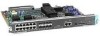
Preparing for Installation 2-11 Network Connection Considerations Figure 2-5 Ethernet Network Processor Module with AUI and 10BaseT Connectors AUI Ethernet 10BaseT TX RX LNK POL AUI H1043a Alignment groove 10BaseT port LEDs AUI port ... to your network. (See Figure 2-6.) Figure 2-6 Single-Port Ethernet Network Processor Module 10BaseT Port Connection 10BaseT hub Ethernet module Router (rear view) AUI 10BASET AUX 10BaseT cable H1524a Figure 2-7 shows a single-port Ethernet network processor module with an Ethernet (AUI) connection to the router port by replacing the slide ...
Preparing for Installation 2-11 Network Connection Considerations Figure 2-5 Ethernet Network Processor Module with AUI and 10BaseT Connectors AUI Ethernet 10BaseT TX RX LNK POL AUI H1043a Alignment groove 10BaseT port LEDs AUI port ... to your network. (See Figure 2-6.) Figure 2-6 Single-Port Ethernet Network Processor Module 10BaseT Port Connection 10BaseT hub Ethernet module Router (rear view) AUI 10BASET AUX 10BaseT cable H1524a Figure 2-7 shows a single-port Ethernet network processor module with an Ethernet (AUI) connection to the router port by replacing the slide ...

Hardware Maintenance Manual
Page 34
...the dual-port Ethernet network processor module, on the module, and the lower port is marked Port-1 on a given port, either a 10BaseT connector or to mate with a slide-latch connector to an AUI connector. 2-12 Cisco 4000 Series Hardware Installation and Maintenance... Network Connection Considerations Router (rear view) Figure 2-7 Single-Port Ethernet Network Processor Module AUI Port Connection Ethernet module Transceiver Slide-latch connector H1525a AUI Router (rear view) ...
...the dual-port Ethernet network processor module, on the module, and the lower port is marked Port-1 on a given port, either a 10BaseT connector or to mate with a slide-latch connector to an AUI connector. 2-12 Cisco 4000 Series Hardware Installation and Maintenance... Network Connection Considerations Router (rear view) Figure 2-7 Single-Port Ethernet Network Processor Module AUI Port Connection Ethernet module Transceiver Slide-latch connector H1525a AUI Router (rear view) ...

Hardware Maintenance Manual
Page 35
...ports DB-15 female Alignment groove Token Ring Connections The dual-port Token Ring network processor module has two standard 9-pin connectors. (See Figure 2-10.) The single-port Token Ring network processor module has one standard 9-pin connector. (See Figure 2-11.) Figure 2-10 Dual-Port ...Token Ring Module Network Connector Token Ring IN-RING B IN-RING A H1980 Alignment groove RING B RING A 16MBPS LEDs DB...
...ports DB-15 female Alignment groove Token Ring Connections The dual-port Token Ring network processor module has two standard 9-pin connectors. (See Figure 2-10.) The single-port Token Ring network processor module has one standard 9-pin connector. (See Figure 2-11.) Figure 2-10 Dual-Port ...Token Ring Module Network Connector Token Ring IN-RING B IN-RING A H1980 Alignment groove RING B RING A 16MBPS LEDs DB...

Hardware Maintenance Manual
Page 36
Network Connection Considerations Figure 2-11 Token Ring Module Network Connector 16MBPS IN-RING H1042a Token Ring Alignment groove LEDs Token Ring port (2 green) Alignment groove Use a standard 9-pin Token Ring lobe cable to connect the router directly to a media attachment unit (MAU). (See Figure 2-12.) Figure 2-12 Token Ring Cable Connections Token Ring lobe cable (not included) 9-pin D connector Router (rear view) H1569a IEEE 802.5 connector Media attachment unit Token Ring port 2-14 Cisco 4000 Series Hardware Installation and Maintenance
Network Connection Considerations Figure 2-11 Token Ring Module Network Connector 16MBPS IN-RING H1042a Token Ring Alignment groove LEDs Token Ring port (2 green) Alignment groove Use a standard 9-pin Token Ring lobe cable to connect the router directly to a media attachment unit (MAU). (See Figure 2-12.) Figure 2-12 Token Ring Cable Connections Token Ring lobe cable (not included) 9-pin D connector Router (rear view) H1569a IEEE 802.5 connector Media attachment unit Token Ring port 2-14 Cisco 4000 Series Hardware Installation and Maintenance

Hardware Maintenance Manual
Page 37
... good results with rates and distances greater than those shown in Table 2-4. The network end of the adapter cable is commonly used. however, the serial module ports support synchronous connections, and the console and auxiliary ports support asynchronous connections. Preparing for each serial interface type; Typically, EIA/TIA-449 and EIA...
... good results with rates and distances greater than those shown in Table 2-4. The network end of the adapter cable is commonly used. however, the serial module ports support synchronous connections, and the console and auxiliary ports support asynchronous connections. Preparing for each serial interface type; Typically, EIA/TIA-449 and EIA...
