
Hardware Maintenance Manual
Page 6
... Initial Hardware Configuration 4-1 Problem Solving 4-1 Troubleshooting the Power and Cooling Systems 4-2 Troubleshooting the Network Processor Modules and Cables 4-2 Environmental Reporting Features 4-3 Reading Front-Panel LED Indicators 4-3 System LED Operation 4-3 Reading Network Processor Module LED Indicators 4-4 Ethernet Network Processor Module LED Indicators ... Main Memory SIMMs 5-11 Replacing Shared-Memory SIMMs 5-13 Inserting Shared-Memory SIMMs 5-14 Removing the Cisco 4500-M and Cisco 4700 Boot Helper Flash Memory SIMM 5-16 Installing Flash-Memory SIMMs 5-17 Replacing Boot ROMs in the...
... Initial Hardware Configuration 4-1 Problem Solving 4-1 Troubleshooting the Power and Cooling Systems 4-2 Troubleshooting the Network Processor Modules and Cables 4-2 Environmental Reporting Features 4-3 Reading Front-Panel LED Indicators 4-3 System LED Operation 4-3 Reading Network Processor Module LED Indicators 4-4 Ethernet Network Processor Module LED Indicators ... Main Memory SIMMs 5-11 Replacing Shared-Memory SIMMs 5-13 Inserting Shared-Memory SIMMs 5-14 Removing the Cisco 4500-M and Cisco 4700 Boot Helper Flash Memory SIMM 5-16 Installing Flash-Memory SIMMs 5-17 Replacing Boot ROMs in the...

Hardware Maintenance Manual
Page 15
..., and selected upgrade and maintenance procedures. Use this publication follow: • Chapter 1, "Cisco 4000 Series Overview," contains an overview of the Cisco 4000 series features and physical specifications. • Chapter 2, "Preparing for Installation," includes safety recommendations, tools and...or electromechanical technician. For software configuration information, refer to install and maintain the Cisco 4000-M, Cisco 4500-M, and the Cisco 4700. Note To order UniverCD, Cisco's online library of this publication to the appropriate software publication. About This Manual...
..., and selected upgrade and maintenance procedures. Use this publication follow: • Chapter 1, "Cisco 4000 Series Overview," contains an overview of the Cisco 4000 series features and physical specifications. • Chapter 2, "Preparing for Installation," includes safety recommendations, tools and...or electromechanical technician. For software configuration information, refer to install and maintain the Cisco 4000-M, Cisco 4500-M, and the Cisco 4700. Note To order UniverCD, Cisco's online library of this publication to the appropriate software publication. About This Manual...

Hardware Maintenance Manual
Page 16
... use in the European Community. xvi Cisco 4000 Series Hardware Installation and Maintenance Document Conventions • Chapter 4, "Troubleshooting the Initial Hardware Configuration," includes a troubleshooting overview, problem-solving instructions, environmental reporting features, and understanding front-panel and network-processor...bar ( | ). Note Means reader take note. You can be used. • Appendix D, "Cisco 4500-M and Cisco 4700 ROM Monitor," describes the Cisco 4500 ROM monitor. • Appendix E, "Operating Conditions for the United Kingdom," describes the operating ...
... use in the European Community. xvi Cisco 4000 Series Hardware Installation and Maintenance Document Conventions • Chapter 4, "Troubleshooting the Initial Hardware Configuration," includes a troubleshooting overview, problem-solving instructions, environmental reporting features, and understanding front-panel and network-processor...bar ( | ). Note Means reader take note. You can be used. • Appendix D, "Cisco 4500-M and Cisco 4700 ROM Monitor," describes the Cisco 4500 ROM monitor. • Appendix E, "Operating Conditions for the United Kingdom," describes the operating ...

Hardware Maintenance Manual
Page 26
The chassis is installed on the airflow patterns in the rack, which can cause immediate or intermittent equipment failure. • Ensure that you are features of the router power supply: • Autoranging power supply (200W, 85 to 264 VAC or 40 to 72 VDC, 50 to 60 Hz) ...• 6-foot electrical power cord 2-4 Cisco 4000 Series Hardware Installation and Maintenance Power Supply Features Following are receiving "clean" power (free of spikes and noise). Install a power conditioner if necessary. • Install proper grounding ...
The chassis is installed on the airflow patterns in the rack, which can cause immediate or intermittent equipment failure. • Ensure that you are features of the router power supply: • Autoranging power supply (200W, 85 to 264 VAC or 40 to 72 VDC, 50 to 60 Hz) ...• 6-foot electrical power cord 2-4 Cisco 4000 Series Hardware Installation and Maintenance Power Supply Features Following are receiving "clean" power (free of spikes and noise). Install a power conditioner if necessary. • Install proper grounding ...

Hardware Maintenance Manual
Page 81
... cannot locate the source of the problem you received the new chassis • Brief description of your system, follow : • Problem Solving • Environmental Reporting Features • Reading Front-Panel LED Indicators • Reading Network Processor Module LED Indicators Use the information in before leaving the factory. Troubleshooting the Initial Hardware...
... cannot locate the source of the problem you received the new chassis • Brief description of your system, follow : • Problem Solving • Environmental Reporting Features • Reading Front-Panel LED Indicators • Reading Network Processor Module LED Indicators Use the information in before leaving the factory. Troubleshooting the Initial Hardware...

Hardware Maintenance Manual
Page 83
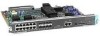
Environmental Reporting Features • System boots, but console screen is operating at a glance. Check the external console connection. - Suspect the network processor module or cable. Figure 4-1 Cisco 4000 Series-Front Panel Indicators Network activity LEDs Run LED 1 DATA OK 2 DATA OK Health LEDs 3 DATA OK SERIES OK POWER Power LED Troubleshooting the... immediately! Verify the console baud rate in the room • Air blockage to the console screen: %SYS-1-OVERTEMP: System detected OVERTEMPERATURE condition. Environmental Reporting Features If the router is frozen. -
Environmental Reporting Features • System boots, but console screen is operating at a glance. Check the external console connection. - Suspect the network processor module or cable. Figure 4-1 Cisco 4000 Series-Front Panel Indicators Network activity LEDs Run LED 1 DATA OK 2 DATA OK Health LEDs 3 DATA OK SERIES OK POWER Power LED Troubleshooting the... immediately! Verify the console baud rate in the room • Air blockage to the console screen: %SYS-1-OVERTEMP: System detected OVERTEMPERATURE condition. Environmental Reporting Features If the router is frozen. -

Hardware Maintenance Manual
Page 127
... ROM Monitor This appendix describes the Cisco 4500-M and Cisco 4700 ROM monitor, the first software to 0x0 by setting the ...the software configuration register (bits 3, 2, 1, and 0) to zero, you reload the router. An example of the Cisco 4500-M and Cisco 4700 ROM monitor prompt follows: rommon 1 > To enable the Break key, and to default to booting at the ROM...-second window, you isolate or rule out hardware problems encountered when installing your router. Cisco 4500-M and Cisco 4700 ROM Monitor D-1 The ROM Monitor can help initialize the processor hardware and boot the main operating ...
... ROM Monitor This appendix describes the Cisco 4500-M and Cisco 4700 ROM monitor, the first software to 0x0 by setting the ...the software configuration register (bits 3, 2, 1, and 0) to zero, you reload the router. An example of the Cisco 4500-M and Cisco 4700 ROM monitor prompt follows: rommon 1 > To enable the Break key, and to default to booting at the ROM...-second window, you isolate or rule out hardware problems encountered when installing your router. Cisco 4500-M and Cisco 4700 ROM Monitor D-1 The ROM Monitor can help initialize the processor hardware and boot the main operating ...

Hardware Maintenance Manual
Page 141
... four-port A-11 X.21 dual-port A-14 four-port A-15 polarity, Ethernet LED 4-5 port locations 2-7 software configuration, serial 4-8 power LED indication 3-22 light 4-3 specifications 1-3 supply features 2-4 system, troubleshooting 4-2 preparing for installation 2-1 to make connections 2-7 preventing ESD damage 2-3 preventive site configuration 2-4 printing summary of ROM monitor commands problem indications 4-3 temperature 4-3 problem solving...
... four-port A-11 X.21 dual-port A-14 four-port A-15 polarity, Ethernet LED 4-5 port locations 2-7 software configuration, serial 4-8 power LED indication 3-22 light 4-3 specifications 1-3 supply features 2-4 system, troubleshooting 4-2 preparing for installation 2-1 to make connections 2-7 preventing ESD damage 2-3 preventive site configuration 2-4 printing summary of ROM monitor commands problem indications 4-3 temperature 4-3 problem solving...