
Hardware Maintenance Manual
Page 2
... reasonable protection against harmful interference when the equipment is operated in a commercial environment. These specifications are subject to be subject to part 15 of the FCC rules. If the interference stops, it was probably caused by the Cisco equipment or one side or the other technical information regarding the products contained in...
... reasonable protection against harmful interference when the equipment is operated in a commercial environment. These specifications are subject to be subject to part 15 of the FCC rules. If the interference stops, it was probably caused by the Cisco equipment or one side or the other technical information regarding the products contained in...
Hardware Maintenance Manual
Page 3
... negligence, or accident, (4) is subject to the Cisco Service Partner if the Software was exported under the multinational uplift program. All other remedy is error free or that Customer will substantially conform to the published specifications for the Software in the event that the Software ...in subparagraph (c) of the Commercial Computer Software Restricted Rights clause at FAR §52.227-19 and subparagraph (c)(1)(ii) of Cisco. To be able to use the Cisco software ("Software") in such a way that supplied the Product to Customer or to change without payment of shipment...
... negligence, or accident, (4) is subject to the Cisco Service Partner if the Software was exported under the multinational uplift program. All other remedy is error free or that Customer will substantially conform to the published specifications for the Software in the event that the Software ...in subparagraph (c) of the Commercial Computer Software Restricted Rights clause at FAR §52.227-19 and subparagraph (c)(1)(ii) of Cisco. To be able to use the Cisco software ("Software") in such a way that supplied the Product to Customer or to change without payment of shipment...

Hardware Maintenance Manual
Page 5
TABLE OF CONTENTS About This Manual xv Document Objectives xv Audience xv Document Organization xv Document Conventions xvi Chapter 1 Cisco 4000 Series Overview 1-1 External Differences in Models of the Cisco 4000 Series 1-1 Series Specifications 1-2 Memory Systems 1-4 Chapter 2 Preparing for Installation 2-1 Safety Recommendations 2-2 Safety with Electricity 2-2 Preventing Electrostatic Discharge Damage 2-3 General Site Requirements 2-3 Site Environment...
TABLE OF CONTENTS About This Manual xv Document Objectives xv Audience xv Document Organization xv Document Conventions xvi Chapter 1 Cisco 4000 Series Overview 1-1 External Differences in Models of the Cisco 4000 Series 1-1 Series Specifications 1-2 Memory Systems 1-4 Chapter 2 Preparing for Installation 2-1 Safety Recommendations 2-2 Safety with Electricity 2-2 Preventing Electrostatic Discharge Damage 2-3 General Site Requirements 2-3 Site Environment...

Hardware Maintenance Manual
Page 7
Testing Your Installation 5-20 Recovering a Lost Password 5-21 Appendix A Cabling Specifications A-1 EIA/TIA-232 Console and Auxiliary Port Pinouts A-2 Serial Cable Pinouts A-3 EIA/TIA-232 Dual Serial Module Cable ...Changing Configuration Register Settings B-2 Configuring the Boot Field B-3 Enabling Booting from Flash Memory B-6 Appendix C Cisco 4000-M ROM Monitor C-1 Entering the Cisco 4000-M ROM Monitor Program C-1 Available ROM Monitor Commands C-2 Appendix D Cisco 4500-M and Cisco 4700 ROM Monitor D-1 Entering the ROM Monitor Program D-1 Available ROM Monitor Commands D-2 ROM Monitor ...
Testing Your Installation 5-20 Recovering a Lost Password 5-21 Appendix A Cabling Specifications A-1 EIA/TIA-232 Console and Auxiliary Port Pinouts A-2 Serial Cable Pinouts A-3 EIA/TIA-232 Dual Serial Module Cable ...Changing Configuration Register Settings B-2 Configuring the Boot Field B-3 Enabling Booting from Flash Memory B-6 Appendix C Cisco 4000-M ROM Monitor C-1 Entering the Cisco 4000-M ROM Monitor Program C-1 Available ROM Monitor Commands C-2 Appendix D Cisco 4500-M and Cisco 4700 ROM Monitor D-1 Entering the ROM Monitor Program D-1 Available ROM Monitor Commands D-2 ROM Monitor ...

Hardware Maintenance Manual
Page 13
... A-10 Table A-11 Table A-12 Table A-13 Table A-14 Table A-15 Table A-16 Table A-17 Table A-18 Table A-19 Table A-20 Cisco 4000 Series Physical Specifications 1-3 Cisco 4000 Series Processor and Memory Specifications 1-3 Unit Numbering for Dual Serial, Ethernet, and Token Ring Modules 2-7 Unit Numbering Addresses for Dual Serial and Two Ethernet Modules 2-8 Unit...
... A-10 Table A-11 Table A-12 Table A-13 Table A-14 Table A-15 Table A-16 Table A-17 Table A-18 Table A-19 Table A-20 Cisco 4000 Series Physical Specifications 1-3 Cisco 4000 Series Processor and Memory Specifications 1-3 Unit Numbering for Dual Serial, Ethernet, and Token Ring Modules 2-7 Unit Numbering Addresses for Dual Serial and Two Ethernet Modules 2-8 Unit...

Hardware Maintenance Manual
Page 15
...and Maintenance publication. Document Organization The major sections of this publication to install and maintain the Cisco 4000-M, Cisco 4500-M, and the Cisco 4700. About This Manual This section discusses the objectives, audience, organization, and conventions of ... date than printed documentation. To order UniverCD, contact your warranty package. Note To order UniverCD, Cisco's online library of the Cisco 4000 series features and physical specifications. • Chapter 2, "Preparing for Installation," includes safety recommendations, tools and equipment, site requirements...
...and Maintenance publication. Document Organization The major sections of this publication to install and maintain the Cisco 4000-M, Cisco 4500-M, and the Cisco 4700. About This Manual This section discusses the objectives, audience, organization, and conventions of ... date than printed documentation. To order UniverCD, contact your warranty package. Note To order UniverCD, Cisco's online library of the Cisco 4000 series features and physical specifications. • Chapter 2, "Preparing for Installation," includes safety recommendations, tools and equipment, site requirements...

Hardware Maintenance Manual
Page 16
... following conventions to materials not contained in this manual. You can be used. • Appendix D, "Cisco 4500-M and Cisco 4700 ROM Monitor," describes the Cisco 4500 ROM monitor. • Appendix E, "Operating Conditions for the United Kingdom," describes the operating conditions ..., replacing or adding network processor modules, and replacing single in-line memory modules (SIMMs). • Appendix A, "Cabling Specifications," provides cable illustrations, cable pinouts, and signal descriptions for the console and auxiliary ports, synchronous serial cables, and Ethernet (AUI) ...
... following conventions to materials not contained in this manual. You can be used. • Appendix D, "Cisco 4500-M and Cisco 4700 ROM Monitor," describes the Cisco 4500 ROM monitor. • Appendix E, "Operating Conditions for the United Kingdom," describes the operating conditions ..., replacing or adding network processor modules, and replacing single in-line memory modules (SIMMs). • Appendix A, "Cabling Specifications," provides cable illustrations, cable pinouts, and signal descriptions for the console and auxiliary ports, synchronous serial cables, and Ethernet (AUI) ...

Hardware Maintenance Manual
Page 20
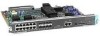
... network interface module ((NP-CE1). Note The Cisco 4500-M and Cisco 4700 support all network processor modules except the single-port Ethernet network processor module and early versions of a Cisco 4000 series router. Series Specifications Figure 1-1 shows the front panel of the ...module in any two other types of network processor modules. Figure 1-1 Cisco 4000 Series Chassis-Front Panel 1 DATA OK 2 DATA OK 3 DATA OK OK POWER SERIES H3590 Series Specifications Design specifications for the Cisco 4000 series follow: • Modular router platform • Flash memory...
... network interface module ((NP-CE1). Note The Cisco 4500-M and Cisco 4700 support all network processor modules except the single-port Ethernet network processor module and early versions of a Cisco 4000 series router. Series Specifications Figure 1-1 shows the front panel of the ...module in any two other types of network processor modules. Figure 1-1 Cisco 4000 Series Chassis-Front Panel 1 DATA OK 2 DATA OK 3 DATA OK OK POWER SERIES H3590 Series Specifications Design specifications for the Cisco 4000 series follow: • Modular router platform • Flash memory...

Hardware Maintenance Manual
Page 21
.../PRI, Channelized T1/PRI, ATM EIA/TIA-2322, EIA/TIA-4491, V.35, X.21, NRZ/NRZI, DTE/DCE; Cisco 4000 Series Overview 1-3 Table 1-2 Cisco 4000 Series Processor and Memory Specifications Description Processor Main Memory (DRAM)2 Cisco 4000-M Cisco 4500-M Cisco 4700 40-MHz Motorola 68EC030 100-MHz IDT Orion RISC1 133-MHz IDT Orion RISC 4, 8, 16, 32...
.../PRI, Channelized T1/PRI, ATM EIA/TIA-2322, EIA/TIA-4491, V.35, X.21, NRZ/NRZI, DTE/DCE; Cisco 4000 Series Overview 1-3 Table 1-2 Cisco 4000 Series Processor and Memory Specifications Description Processor Main Memory (DRAM)2 Cisco 4000-M Cisco 4500-M Cisco 4700 40-MHz Motorola 68EC030 100-MHz IDT Orion RISC1 133-MHz IDT Orion RISC 4, 8, 16, 32...

Hardware Maintenance Manual
Page 25
... individual chassis and the layout of your equipment rack or wiring room are currently experiencing shutdowns or unusually high errors with any equipment that is specifically designed for safe installation and operation of your system. If you are extremely important for Installation 2-3 Equipment placed too close together, inadequate ventilation, and inaccessible...
... individual chassis and the layout of your equipment rack or wiring room are currently experiencing shutdowns or unusually high errors with any equipment that is specifically designed for safe installation and operation of your system. If you are extremely important for Installation 2-3 Equipment placed too close together, inadequate ventilation, and inaccessible...

Hardware Maintenance Manual
Page 27
... later in this section.) Figure 2-1 Installation Checklist Installation Checklist for Site Task Installation Checklist copied for each system Background information placed in Site Log Environmental specifications verified Site power voltages verified Installation site prepower check completed Required tools available Additional equipment available Router received Printed documentation or UniverCD received (if ordered...
... later in this section.) Figure 2-1 Installation Checklist Installation Checklist for Site Task Installation Checklist copied for each system Background information placed in Site Log Environmental specifications verified Site power voltages verified Installation site prepower check completed Required tools available Additional equipment available Router received Printed documentation or UniverCD received (if ordered...

Hardware Maintenance Manual
Page 31
In the appendix "Cabling Specifications," Table A-1 lists the pinout for the Cisco 4000-M and Table A-2 lists the pinout for network access. The AUX port is included on all router units. Preparing for the Cisco 4500-M and Cisco 4700 console port. Console Port Connections Each ...baud • 8 data bits • No parity generated or checked • 2 stop bits In the appendix "Cabling Specifications," Table A-1 lists the pinout for the Cisco 4000-M console port and Table A-2 lists the pinout for Installation 2-9 Auxiliary Port Connections A male DB-25 connector auxiliary port...
In the appendix "Cabling Specifications," Table A-1 lists the pinout for the Cisco 4000-M and Table A-2 lists the pinout for network access. The AUX port is included on all router units. Preparing for the Cisco 4500-M and Cisco 4700 console port. Console Port Connections Each ...baud • 8 data bits • No parity generated or checked • 2 stop bits In the appendix "Cabling Specifications," Table A-1 lists the pinout for the Cisco 4000-M console port and Table A-2 lists the pinout for Installation 2-9 Auxiliary Port Connections A male DB-25 connector auxiliary port...

Hardware Maintenance Manual
Page 39
...TIA-449 on the smaller, DB-25 connector used successfully at the network end of 2 Mbps, EIA-530 is used for Installation 2-17 Although the specification recommends a maximum speed of the adapter cable. Figure 2-17 shows the DB-25 connector at 4 Mbps or faster speeds over short distances. The network...are available as a result, requires fewer circuits and a smaller connector than EIA/TIA-232. Like EIA/TIA-449, EIA-530 refers to the electrical specifications of the EIA-530 adapter cable is available in the United Kingdom to the DTE and DCE interfaces and, as either DTE (DB-15 plug...
...TIA-449 on the smaller, DB-25 connector used successfully at the network end of 2 Mbps, EIA-530 is used for Installation 2-17 Although the specification recommends a maximum speed of the adapter cable. Figure 2-17 shows the DB-25 connector at 4 Mbps or faster speeds over short distances. The network...are available as a result, requires fewer circuits and a smaller connector than EIA/TIA-232. Like EIA/TIA-449, EIA-530 refers to the electrical specifications of the EIA-530 adapter cable is available in the United Kingdom to the DTE and DCE interfaces and, as either DTE (DB-15 plug...

Hardware Maintenance Manual
Page 43
... configuration of the port-for NRZI, move the jumpers to a modem, CSU/DSU, or other device as DTE in Figure 2-23. See the appendix "Cabling Specifications." Nine different serial cables are not interchangeable. This cable, available from your customer service representative, is not configured. For more information on software commands, refer...
... configuration of the port-for NRZI, move the jumpers to a modem, CSU/DSU, or other device as DTE in Figure 2-23. See the appendix "Cabling Specifications." Nine different serial cables are not interchangeable. This cable, available from your customer service representative, is not configured. For more information on software commands, refer...

Hardware Maintenance Manual
Page 52
... PRI. Network Connection Considerations The specifications for transmitting and receiving data bidirectionally at the T1 rate of 1.544 Mbps. On the CT1, the controller provides up to the system as a concentrator for a remote site. 2-30 Cisco 4000 Series Hardware Installation and Maintenance... Table 2-6 BRI Cable Specifications Parameter Resistance (@ 96 kHz1) Capacitance (@ 1 kHz) High-Capacitance Cable 160 ohms/km 120 nF/km2 Low...
... PRI. Network Connection Considerations The specifications for transmitting and receiving data bidirectionally at the T1 rate of 1.544 Mbps. On the CT1, the controller provides up to the system as a concentrator for a remote site. 2-30 Cisco 4000 Series Hardware Installation and Maintenance... Table 2-6 BRI Cable Specifications Parameter Resistance (@ 96 kHz1) Capacitance (@ 1 kHz) High-Capacitance Cable 160 ohms/km 120 nF/km2 Low...

Hardware Maintenance Manual
Page 53
... DSX • Output pulse width: 324 nanoseconds (ns) ± 54 ns • Complies with all AT&T Accunet TR 62411 specifications For the CT1, two standard T1 serial cables are available from Cisco Systems: null-modem and straight-through cable connects your router to connect the CT1with the external CSU. Network Connection Considerations...
... DSX • Output pulse width: 324 nanoseconds (ns) ± 54 ns • Complies with all AT&T Accunet TR 62411 specifications For the CT1, two standard T1 serial cables are available from Cisco Systems: null-modem and straight-through cable connects your router to connect the CT1with the external CSU. Network Connection Considerations...

Hardware Maintenance Manual
Page 54
... unit (CSU). On the CE1, the controller provides up to 120-ohm. 2-32 Cisco 4000 Series Hardware Installation and Maintenance Figure 2-34 Channelized E1 Network Interface Processor cE1 / PRI DB-15 female Following are the E1 specifications: • Transmission bit rate: 2.048 Mbps ± 50 ppm • Output... the cable resistance (120-ohm or 75-ohm). By default, the CE1 module is presented to the system as described in the G.703 specification. This interface is the physical media that can function as stated in Table 2-7. For wide-area networking, the CE1 can be configured individually...
... unit (CSU). On the CE1, the controller provides up to 120-ohm. 2-32 Cisco 4000 Series Hardware Installation and Maintenance Figure 2-34 Channelized E1 Network Interface Processor cE1 / PRI DB-15 female Following are the E1 specifications: • Transmission bit rate: 2.048 Mbps ± 50 ppm • Output... the cable resistance (120-ohm or 75-ohm). By default, the CE1 module is presented to the system as described in the G.703 specification. This interface is the physical media that can function as stated in Table 2-7. For wide-area networking, the CE1 can be configured individually...

Hardware Maintenance Manual
Page 56
...optical-STS-3c or STM-1 (See Figure 2-40) All ATM interfaces are full-duplex. the actual rate is not occupied by the specific physical layer). The ATM processor module supports PLIMs that connect to connect the ATM processor module with RJ-45 Connector) H2422 ATM Connections ...The ATM processor module for a Cisco 4000 series router provides a user network interface (UNI) between the router and an ATM network. Network Connection Considerations Figure 2-37 E1 Interface...
...optical-STS-3c or STM-1 (See Figure 2-40) All ATM interfaces are full-duplex. the actual rate is not occupied by the specific physical layer). The ATM processor module supports PLIMs that connect to connect the ATM processor module with RJ-45 Connector) H2422 ATM Connections ...The ATM processor module for a Cisco 4000 series router provides a user network interface (UNI) between the router and an ATM network. Network Connection Considerations Figure 2-37 E1 Interface...

Hardware Maintenance Manual
Page 58
...UniverCD , as specified by the customer order Inspect all PLIMs. Warning Invisible laser radiation can be shipped in the Warranty Package). 2-36 Cisco 4000 Series Hardware Installation and Maintenance This product meets the Class 1 Laser Emission Requirement from the aperture ports of the single-mode ATM ...products when no fiber-optic cable is the yellow laser warning label on the single-mode module's front panel, or the specific part number visible on the upper surface of rubber feet for desktop mounting • Optional equipment (which might be emitted from CDRH FDDI...
...UniverCD , as specified by the customer order Inspect all PLIMs. Warning Invisible laser radiation can be shipped in the Warranty Package). 2-36 Cisco 4000 Series Hardware Installation and Maintenance This product meets the Class 1 Laser Emission Requirement from the aperture ports of the single-mode ATM ...products when no fiber-optic cable is the yellow laser warning label on the single-mode module's front panel, or the specific part number visible on the upper surface of rubber feet for desktop mounting • Optional equipment (which might be emitted from CDRH FDDI...

Hardware Maintenance Manual
Page 61
... to a single connector on the same module. For dual-port Ethernet modules (see Figure 3-3), connect either the Ethernet AUI connector or the 10BaseT connector on a specific Ethernet port, but not both connectors on the right shows a supported connection with a single 10BaseT cable connecting to Port 0, is supported. Figure 3-3 Unsupported and Supported...
... to a single connector on the same module. For dual-port Ethernet modules (see Figure 3-3), connect either the Ethernet AUI connector or the 10BaseT connector on a specific Ethernet port, but not both connectors on the right shows a supported connection with a single 10BaseT cable connecting to Port 0, is supported. Figure 3-3 Unsupported and Supported...