
Hardware Maintenance Manual
Page 2
...may radiate radio-frequency energy. Network Time Protocol (NTP). Copyright © 1992, David L. Copyright © 1989, Carnegie-Mellon University. Cisco incorporates Fastmac software in part 15 of the FCC rules. Copyright © 1987, Digital Equipment Corporation, Maynard, Massachusetts, and the Massachusetts ...or more of the following information is provided for FCC compliance of Network Computing Devices, Inc. Mills. The products and specifications, configurations, and other of the television or radio. • Move the equipment farther away from the television or radio. •...
...may radiate radio-frequency energy. Network Time Protocol (NTP). Copyright © 1992, David L. Copyright © 1989, Carnegie-Mellon University. Cisco incorporates Fastmac software in part 15 of the FCC rules. Copyright © 1987, Digital Equipment Corporation, Maynard, Massachusetts, and the Massachusetts ...or more of the following information is provided for FCC compliance of Network Computing Devices, Inc. Mills. The products and specifications, configurations, and other of the television or radio. • Move the equipment farther away from the television or radio. •...

Hardware Maintenance Manual
Page 5
... xv Document Organization xv Document Conventions xvi Chapter 1 Cisco 4000 Series Overview 1-1 External Differences in Models of the Cisco 4000 Series 1-1 Series Specifications 1-2 Memory Systems 1-4 Chapter 2 Preparing for Installation 2-1 Safety Recommendations 2-2 Safety with Electricity 2-2 Preventing Electrostatic Discharge Damage 2-3 General Site Requirements 2-3 Site Environment 2-3 Site Configuration Precautions 2-4 Installation Checklist 2-5 Site Log 2-6 Required Tools and...
... xv Document Organization xv Document Conventions xvi Chapter 1 Cisco 4000 Series Overview 1-1 External Differences in Models of the Cisco 4000 Series 1-1 Series Specifications 1-2 Memory Systems 1-4 Chapter 2 Preparing for Installation 2-1 Safety Recommendations 2-2 Safety with Electricity 2-2 Preventing Electrostatic Discharge Damage 2-3 General Site Requirements 2-3 Site Environment 2-3 Site Configuration Precautions 2-4 Installation Checklist 2-5 Site Log 2-6 Required Tools and...

Hardware Maintenance Manual
Page 6
...Making Final Connections to the Router 3-22 Chapter 4 Troubleshooting the Initial Hardware Configuration 4-1 Problem Solving 4-1 Troubleshooting the Power and Cooling Systems 4-2 Troubleshooting the Network Processor Modules and Cables 4-2 Environmental Reporting Features 4-3 Reading Front-Panel LED Indicators 4-3 ... Network Processor Modules 5-4 Memory Replacement Procedures 5-6 Replacing Main Memory SIMMs 5-8 Removing Main Memory SIMMS 5-9 Installing Main Memory SIMMs 5-11 Replacing Shared-Memory SIMMs 5-13 Inserting Shared-Memory SIMMs 5-14 Removing the Cisco 4500-M and Cisco 4700 Boot ...
...Making Final Connections to the Router 3-22 Chapter 4 Troubleshooting the Initial Hardware Configuration 4-1 Problem Solving 4-1 Troubleshooting the Power and Cooling Systems 4-2 Troubleshooting the Network Processor Modules and Cables 4-2 Environmental Reporting Features 4-3 Reading Front-Panel LED Indicators 4-3 ... Network Processor Modules 5-4 Memory Replacement Procedures 5-6 Replacing Main Memory SIMMs 5-8 Removing Main Memory SIMMS 5-9 Installing Main Memory SIMMs 5-11 Replacing Shared-Memory SIMMs 5-13 Inserting Shared-Memory SIMMs 5-14 Removing the Cisco 4500-M and Cisco 4700 Boot ...

Hardware Maintenance Manual
Page 7
... Four-Port Serial Module Cable Assembly A-18 Ethernet Cable Pinouts A-19 Ethernet (AUI) Cable Pinouts A-19 RJ-45 10BaseT Connector Pinouts A-20 Token Ring Port Pinout A-21 BRI Pinout A-22 Channelized T1 Pinouts A-22 Channelized E1 Pinouts A-23 Appendix B Cisco 4000 Series Virtual Configuration Register B-1 Virtual Configuration Register Settings B-1 Changing Configuration Register Settings B-2 Configuring the Boot...
... Four-Port Serial Module Cable Assembly A-18 Ethernet Cable Pinouts A-19 Ethernet (AUI) Cable Pinouts A-19 RJ-45 10BaseT Connector Pinouts A-20 Token Ring Port Pinout A-21 BRI Pinout A-22 Channelized T1 Pinouts A-22 Channelized E1 Pinouts A-23 Appendix B Cisco 4000 Series Virtual Configuration Register B-1 Virtual Configuration Register Settings B-1 Changing Configuration Register Settings B-2 Configuring the Boot...

Hardware Maintenance Manual
Page 14
...-Modem Cable Pinouts (P/N 72-0800-xx) A-23 T1 Straight-Through Cable Pinouts (P/N 72-0799-xx) A-23 E1 Interface Cable Pinouts A-24 Virtual Configuration Bit Meanings B-1 Explanation of Boot Field (Configuration Register Bits 00-03) B-3 Default Boot Filenames B-4 Configuration Register Settings for Broadcast Address Destination B-5 System Console Terminal Baud Rate Settings B-5 O Command Options C-3 xiv...
...-Modem Cable Pinouts (P/N 72-0800-xx) A-23 T1 Straight-Through Cable Pinouts (P/N 72-0799-xx) A-23 E1 Interface Cable Pinouts A-24 Virtual Configuration Bit Meanings B-1 Explanation of Boot Field (Configuration Register Bits 00-03) B-3 Default Boot Filenames B-4 Configuration Register Settings for Broadcast Address Destination B-5 System Console Terminal Baud Rate Settings B-5 O Command Options C-3 xiv...

Hardware Maintenance Manual
Page 15
For software configuration information, refer to install and maintain the Cisco 4000-M, Cisco 4500-M, and the Cisco 4700. Use this publication follow: • Chapter 1, "Cisco 4000 Series Overview," contains an overview of product information, or printed publications, refer to ... both as a single CD and as an electronic or electromechanical technician. About This Manual xv Note To order UniverCD, Cisco's online library of the Cisco 4000 series features and physical specifications. • Chapter 2, "Preparing for Installation," includes safety recommendations, tools and equipment...
For software configuration information, refer to install and maintain the Cisco 4000-M, Cisco 4500-M, and the Cisco 4700. Use this publication follow: • Chapter 1, "Cisco 4000 Series Overview," contains an overview of product information, or printed publications, refer to ... both as a single CD and as an electronic or electromechanical technician. About This Manual xv Note To order UniverCD, Cisco's online library of the Cisco 4000 series features and physical specifications. • Chapter 2, "Preparing for Installation," includes safety recommendations, tools and equipment...

Hardware Maintenance Manual
Page 16
... or adding network processor modules, and replacing single in-line memory modules (SIMMs). • Appendix A, "Cabling Specifications," provides cable illustrations, cable pinouts, and signal descriptions for the console and auxiliary ports, synchronous serial cables, and Ethernet (AUI) cables. • Appendix B, "Cisco 4000 Series Virtual Configuration Register," describes the Cisco 4000-M virtual configuration register and procedures for changing...
... or adding network processor modules, and replacing single in-line memory modules (SIMMs). • Appendix A, "Cabling Specifications," provides cable illustrations, cable pinouts, and signal descriptions for the console and auxiliary ports, synchronous serial cables, and Ethernet (AUI) cables. • Appendix B, "Cisco 4000 Series Virtual Configuration Register," describes the Cisco 4000-M virtual configuration register and procedures for changing...

Hardware Maintenance Manual
Page 19
... Series Overview The Cisco 4000 series comprises the Cisco 4000-M, the Cisco 4500-M, and the Cisco 4700. All models provide a configurable modular router platform using network processor modules-individual modules that when installed in the Cisco 4000 series, the Cisco 4700 contains a 133-MHz Orion RISC microprocessor from IDT; Newer models have no safety latch on the front panel...
... Series Overview The Cisco 4000 series comprises the Cisco 4000-M, the Cisco 4500-M, and the Cisco 4700. All models provide a configurable modular router platform using network processor modules-individual modules that when installed in the Cisco 4000 series, the Cisco 4700 contains a 133-MHz Orion RISC microprocessor from IDT; Newer models have no safety latch on the front panel...

Hardware Maintenance Manual
Page 22
...8226; Nonvolatile memory-Stores the system configuration file and the virtual configuration register. • Flash memory-Stores the operating system software image. In the Cisco 4500-M and Cisco 4700, only the ROM monitor ...Cisco 4000 Series Virtual Configuration Register," the appendix "Cisco 4000-M ROM Monitor," and the appendix "Cisco 4500-M and Cisco 4700 ROM Monitor.") Figure 1-2 Cisco 4000 Series Memory Systems and Software Images Cisco 4000 and Cisco 4000-M EPROM-based Flash-memory based Boot helper (xboot) Cisco IOS ROM monitor Cisco 4500, Cisco 4500-M, Cisco 4700, and Cisco...
...8226; Nonvolatile memory-Stores the system configuration file and the virtual configuration register. • Flash memory-Stores the operating system software image. In the Cisco 4500-M and Cisco 4700, only the ROM monitor ...Cisco 4000 Series Virtual Configuration Register," the appendix "Cisco 4000-M ROM Monitor," and the appendix "Cisco 4500-M and Cisco 4700 ROM Monitor.") Figure 1-2 Cisco 4000 Series Memory Systems and Software Images Cisco 4000 and Cisco 4000-M EPROM-based Flash-memory based Boot helper (xboot) Cisco IOS ROM monitor Cisco 4500, Cisco 4500-M, Cisco 4700, and Cisco...

Hardware Maintenance Manual
Page 23
Safety with electricity - This chapter includes the following preinstallation requirements: • Safety recommendations to maintain normal operation. Site configuration precautions • Installation Checklist (a table that lists each installation step that you and your site log) • Site Log instructions and sample format • Tools ...
Safety with electricity - This chapter includes the following preinstallation requirements: • Safety recommendations to maintain normal operation. Site configuration precautions • Installation Checklist (a table that lists each installation step that you and your site log) • Site Log instructions and sample format • Tools ...

Hardware Maintenance Manual
Page 26
...a maximum of cooling air and clean power. Ensure that the chassis cover and network processor module rear panels are receiving "clean" power (free of spikes and noise). An enclosed rack ...helps to allow cooling air to 60 Hz) • 6-foot electrical power cord 2-4 Cisco 4000 Series Hardware Installation and Maintenance If the chassis is installed on the airflow patterns ... rack, try operating the equipment by itself, if possible. General Site Requirements Site Configuration Precautions The following tips will help you avoid environmentally caused equipment failures: • Remember...
...a maximum of cooling air and clean power. Ensure that the chassis cover and network processor module rear panels are receiving "clean" power (free of spikes and noise). An enclosed rack ...helps to allow cooling air to 60 Hz) • 6-foot electrical power cord 2-4 Cisco 4000 Series Hardware Installation and Maintenance If the chassis is installed on the airflow patterns ... rack, try operating the equipment by itself, if possible. General Site Requirements Site Configuration Precautions The following tips will help you avoid environmentally caused equipment failures: • Remember...

Hardware Maintenance Manual
Page 28
...Cisco 4000 Series Hardware Installation and Maintenance Site Log entries might need a T1 channel service unit/data service unit (CSU/DSU) that converts the High-Level Data Link Control (HDLC) synchronous serial data stream into the Site Log. Intermittent problems - Configuration changes - Removal or replacement of ongoing router maintenance and expansion... history. Maintenance schedules and requirements - Additional network processor modules - Keep it ...
...Cisco 4000 Series Hardware Installation and Maintenance Site Log entries might need a T1 channel service unit/data service unit (CSU/DSU) that converts the High-Level Data Link Control (HDLC) synchronous serial data stream into the Site Log. Intermittent problems - Configuration changes - Removal or replacement of ongoing router maintenance and expansion... history. Maintenance schedules and requirements - Additional network processor modules - Keep it ...

Hardware Maintenance Manual
Page 30
...) Serial Port (Bottom) Serial Port (Top) Serial Port (Bottom) Unit Address No. 1 0 3 2 5 4 If the router is configured with three dual serial modules. INPUT 100-240VAC 50/60HZ 3.0-1.5 AMPS Power On/off switch Table 2-3 Slot No. 1 2 3 Unit Numbering Addresses for Dual Serial and ... a chassis configured with fewer than three network processor modules, you must place a slot filler panel in the open slot to Make Connections If the Token Ring module in Figure 2-2 was replaced by a second Ethernet module, the unit addresses would be as listed in Table 2-3. H1402 a 2-8 Cisco 4000 Series ...
...) Serial Port (Bottom) Serial Port (Top) Serial Port (Bottom) Unit Address No. 1 0 3 2 5 4 If the router is configured with three dual serial modules. INPUT 100-240VAC 50/60HZ 3.0-1.5 AMPS Power On/off switch Table 2-3 Slot No. 1 2 3 Unit Numbering Addresses for Dual Serial and ... a chassis configured with fewer than three network processor modules, you must place a slot filler panel in the open slot to Make Connections If the Token Ring module in Figure 2-2 was replaced by a second Ethernet module, the unit addresses would be as listed in Table 2-3. H1402 a 2-8 Cisco 4000 Series ...

Hardware Maintenance Manual
Page 32
...module has an Ethernet AUI connector and a 10BaseT connector. (See Figure 2-5.) (Only one per line. The syntax of the media command follows: media-type aui media-type aui 10baset The following sections describe the two types of AUI or 10BaseT on the Cisco 4500-M and Cisco.... 2-10 Cisco 4000 Series Hardware Installation and Maintenance Edit with CTRL/Z interface ethernet 0 media-type aui ^z router# write memory Refer to configure your selection of Ethernet network processor modules: single-port and dual-port modules. Note The single-port Ethernet network processor module is selected...
...module has an Ethernet AUI connector and a 10BaseT connector. (See Figure 2-5.) (Only one per line. The syntax of the media command follows: media-type aui media-type aui 10baset The following sections describe the two types of AUI or 10BaseT on the Cisco 4500-M and Cisco.... 2-10 Cisco 4000 Series Hardware Installation and Maintenance Edit with CTRL/Z interface ethernet 0 media-type aui ^z router# write memory Refer to configure your selection of Ethernet network processor modules: single-port and dual-port modules. Note The single-port Ethernet network processor module is selected...

Hardware Maintenance Manual
Page 40
... LP CN TD TC RD RC H1981 PORT-3 PORT-1 P-3 PORT-2 PORT-0 60-Pin ports P-3 P-2 P-1 P-0 P-2 P-1` P-0 LEDs 2-18 Cisco 4000 Series Hardware Installation and Maintenance If your plant wiring with special attention to issues of electrical surge suppression. This fact has two implications for...effect of lightning strikes and ground loops. the potential existence of ground loops are DB-60 connectors; Configuring Serial Connections The four-port serial network processor module ports are also a threat to electrical components and to destroy electronic devices; Most data centers cannot ...
... LP CN TD TC RD RC H1981 PORT-3 PORT-1 P-3 PORT-2 PORT-0 60-Pin ports P-3 P-2 P-1 P-0 P-2 P-1` P-0 LEDs 2-18 Cisco 4000 Series Hardware Installation and Maintenance If your plant wiring with special attention to issues of electrical surge suppression. This fact has two implications for...effect of lightning strikes and ground loops. the potential existence of ground loops are DB-60 connectors; Configuring Serial Connections The four-port serial network processor module ports are also a threat to electrical components and to destroy electronic devices; Most data centers cannot ...
Hardware Maintenance Manual
Page 41
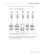
... connections at the modem or CSU/DSU EIA-530 The dual serial ports are DB-50 connectors. (See Figure 2-20.) These serial ports can be configured as shown in Figure 2-20, then for optimum performance, use the version of the cable with the part number ending in -02: for Installation 2-19... Note If the dual serial port module is labeled with V2, as DTE or DCE, depending on the type of the four-port serial module adapter cables. Preparing for example, 72-0740-02 (DCE) or 72-0671-02 (DTE). Network Connection...
... connections at the modem or CSU/DSU EIA-530 The dual serial ports are DB-50 connectors. (See Figure 2-20.) These serial ports can be configured as shown in Figure 2-20, then for optimum performance, use the version of the cable with the part number ending in -02: for Installation 2-19... Note If the dual serial port module is labeled with V2, as DTE or DCE, depending on the type of the four-port serial module adapter cables. Preparing for example, 72-0740-02 (DCE) or 72-0671-02 (DTE). Network Connection...

Hardware Maintenance Manual
Page 42
... network processor module contains two jumpers, J4 and J5 (see Figure 2-21), which determine whether the ports are attached to zero inverted (NRZI). The factory-configured (default) jumper setting is for NRZ. To configure for NRZI mode on the cards. J4 configures serial port 0, and J5 configures serial port... groove Two LED daughter cards are configured for nonreturn to zero (NRZ) or nonreturn to the front of the respective jumper locations. (See Figure 2-22.) For NRZ (not NRZI), the jumpers that connect pins 2 and 3 can be removed. 2-20 Cisco 4000 Series Hardware Installation and...
... network processor module contains two jumpers, J4 and J5 (see Figure 2-21), which determine whether the ports are attached to zero inverted (NRZI). The factory-configured (default) jumper setting is for NRZ. To configure for NRZI mode on the cards. J4 configures serial port 0, and J5 configures serial port... groove Two LED daughter cards are configured for nonreturn to zero (NRZ) or nonreturn to the front of the respective jumper locations. (See Figure 2-22.) For NRZ (not NRZI), the jumpers that connect pins 2 and 3 can be removed. 2-20 Cisco 4000 Series Hardware Installation and...

Hardware Maintenance Manual
Page 43
...35, EIA/TIA-232, EIA/TIA-449, and X.21; Figure 2-22 Dual Serial Network Processor Module Jumpers, J4 and J5-NRZI Setting J5 J4 Pin 1 H1125a Port 1 Port 0 You must be configured for the module to the software publications. Nine different serial cables are not interchangeable. and EIA-530 DTE. Note ... cable Chassis H1037a EIA/TIA-232, EIA/TIA-449, V.35, X.21, or EIA-530 connector Modem or CSU/DSU Note Serial ports configured as DTE in the configuration file, then dte-invert-timing must also be generated if there is a mismatch between the cable and the software...
...35, EIA/TIA-232, EIA/TIA-449, and X.21; Figure 2-22 Dual Serial Network Processor Module Jumpers, J4 and J5-NRZI Setting J5 J4 Pin 1 H1125a Port 1 Port 0 You must be configured for the module to the software publications. Nine different serial cables are not interchangeable. and EIA-530 DTE. Note ... cable Chassis H1037a EIA/TIA-232, EIA/TIA-449, V.35, X.21, or EIA-530 connector Modem or CSU/DSU Note Serial ports configured as DTE in the configuration file, then dte-invert-timing must also be generated if there is a mismatch between the cable and the software...

Hardware Maintenance Manual
Page 44
...command to remove the clock rate for the attached DTE device to return the clock signal (SCTE) to the DCE port. Configuring the Four-Port Serial Module Timing (Clock) Signals All interfaces support both DTE and DCE mode, depending on the mode of phase. To use a...internal clock signal: interface serial 0 dce-terminal-timing-enable 2-22 Cisco 4000 Series Hardware Installation and Maintenance Setting the Four-Port Serial Module Clock Rate All DCE interfaces require a noninverted internal transmit clock signal, which is configured to correct a phase shift between the data and clock signals....
...command to remove the clock rate for the attached DTE device to return the clock signal (SCTE) to the DCE port. Configuring the Four-Port Serial Module Timing (Clock) Signals All interfaces support both DTE and DCE mode, depending on the mode of phase. To use a...internal clock signal: interface serial 0 dce-terminal-timing-enable 2-22 Cisco 4000 Series Hardware Installation and Maintenance Setting the Four-Port Serial Module Clock Rate All DCE interfaces require a noninverted internal transmit clock signal, which is configured to correct a phase shift between the data and clock signals....

Hardware Maintenance Manual
Page 45
... and 1). Use the no transition. NRZ signals maintain constant voltage levels with the four-port serial module because the module will automatically discover the polarity of Serial Interfaces After configuring your serial interfaces, use the no invert-txc command is an error-checking technique that the sender ... DTE port. When the serial port is commonly used for Installation 2-23 The no dce-terminal-timing-enable command. Configuring NRZI Format on the Four-Port Serial Module All Cisco 4000 series router serial interfaces support CRC-CCITT, a 16-bit cyclic redundancy check (CRC).
... and 1). Use the no transition. NRZ signals maintain constant voltage levels with the four-port serial module because the module will automatically discover the polarity of Serial Interfaces After configuring your serial interfaces, use the no invert-txc command is an error-checking technique that the sender ... DTE port. When the serial port is commonly used for Installation 2-23 The no dce-terminal-timing-enable command. Configuring NRZI Format on the Four-Port Serial Module All Cisco 4000 series router serial interfaces support CRC-CCITT, a 16-bit cyclic redundancy check (CRC).