
Hardware Maintenance Manual
Page 73
... the CT1 module. Refer to the printed Router Products Configuration Guide and Router Products Command Reference publications or UniverCD for a summary of the configuration subcommands, to complete the configuration, enter ^Z (hold down %LINEPROTO-5-UPDOWN: Line protocol on Interface...Installing the Router 3-15 Making Network Connections Step 6 At the prompt, specify the channel-group modification command, channel-group and timeslots to the interface with show commands. Router(config-controller)# channel-group 0 timeslots 1,3-5,7 Router(config-controller)# %LINEPROTO-5-UPDOWN: Line...
... the CT1 module. Refer to the printed Router Products Configuration Guide and Router Products Command Reference publications or UniverCD for a summary of the configuration subcommands, to complete the configuration, enter ^Z (hold down %LINEPROTO-5-UPDOWN: Line protocol on Interface...Installing the Router 3-15 Making Network Connections Step 6 At the prompt, specify the channel-group modification command, channel-group and timeslots to the interface with show commands. Router(config-controller)# channel-group 0 timeslots 1,3-5,7 Router(config-controller)# %LINEPROTO-5-UPDOWN: Line...

Hardware Maintenance Manual
Page 75
... the ATM interface that the new interface is stored. After you must enter the configuration mode. Refer to the printed Router Products Configuration Guide and Router Products Command Reference publications or UniverCD for a summary of the configuration subcommands: Router# conf t Step 2 Specify the unit ...is the default): Router(config-if)#atm sonet stm-1 Step 4 Assign protocol addresses to configure the new ATM module. Making ATM Connections If you installed a new ATM interface module or if you want to the user level by atm and the unit number. Step 10 Exit the privileged...
... the ATM interface that the new interface is stored. After you must enter the configuration mode. Refer to the printed Router Products Configuration Guide and Router Products Command Reference publications or UniverCD for a summary of the configuration subcommands: Router# conf t Step 2 Specify the unit ...is the default): Router(config-if)#atm sonet stm-1 Step 4 Assign protocol addresses to configure the new ATM module. Making ATM Connections If you installed a new ATM interface module or if you want to the user level by atm and the unit number. Step 10 Exit the privileged...

Hardware Maintenance Manual
Page 104
... Memory SIMMs." 5-10 Cisco 4000 Series Hardware Installation and Maintenance Side view 2. The SIMM will not release unless the clips have cleared the back of the SIMM. SIMM polarization notch H1153 3. The socket guide posts release through the SIMM holes (on both sides). 1. The socket guide posts release through the SIMM holes (on both...
... Memory SIMMs." 5-10 Cisco 4000 Series Hardware Installation and Maintenance Side view 2. The SIMM will not release unless the clips have cleared the back of the SIMM. SIMM polarization notch H1153 3. The socket guide posts release through the SIMM holes (on both sides). 1. The socket guide posts release through the SIMM holes (on both...

Hardware Maintenance Manual
Page 105
... 5-6 for the Cisco 4500-M and Cisco 4700. Step 2 On the motherboard, locate the main memory SIMM card sockets shown in this procedure to the metal back plate of the chassis, avoiding contact with the plastic socket guides on the socket. SIMMs are ESD-sensitive components and can be empty. Memory Replacement Procedures Installing Main Memory...
... 5-6 for the Cisco 4500-M and Cisco 4700. Step 2 On the motherboard, locate the main memory SIMM card sockets shown in this procedure to the metal back plate of the chassis, avoiding contact with the plastic socket guides on the socket. SIMMs are ESD-sensitive components and can be empty. Memory Replacement Procedures Installing Main Memory...
Hardware Maintenance Manual
Page 106
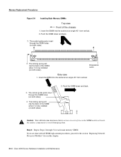
...through the SIMM holes (on both sides). Push the SIMM down and back. Push the SIMM down and back. 3. The socket guide posts insert through 5 for each main memory SIMM. Insert the SIMM into the socket at an angle 45° from vertical....the surface components to the section "Replacing Network Processor Modules" later in this chapter. 5-12 Cisco 4000 Series Hardware Installation and Maintenance Memory Replacement Procedures Figure 5-9 Installing Main Memory SIMMs Top view Front of the SIMM when it is fully installed (on both sides). 4. H1152 Caution You will...
...through the SIMM holes (on both sides). Push the SIMM down and back. Push the SIMM down and back. 3. The socket guide posts insert through 5 for each main memory SIMM. Insert the SIMM into the socket at an angle 45° from vertical....the surface components to the section "Replacing Network Processor Modules" later in this chapter. 5-12 Cisco 4000 Series Hardware Installation and Maintenance Memory Replacement Procedures Figure 5-9 Installing Main Memory SIMMs Top view Front of the SIMM when it is fully installed (on both sides). 4. H1152 Caution You will...

Hardware Maintenance Manual
Page 111
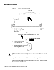
...-degree angle and rock it into its vertical position. (See Figure 5-5 and Figure 5-6.) When the SIMM is properly seated, the socket guide posts will insert through the alignment holes, and the locking springs will click into place. Maintaining and Upgrading the Router 5-17 SIMMs are...Use the minimum amount of force required. Take the following steps to the empty socket (labeled System Flash Memory 1). Memory Replacement Procedures Installing Flash-Memory SIMMs You upgrade boot helper Flash memory by replacing the existing SIMM (labeled System Flash Memory 0), or by adding a second...
...-degree angle and rock it into its vertical position. (See Figure 5-5 and Figure 5-6.) When the SIMM is properly seated, the socket guide posts will insert through the alignment holes, and the locking springs will click into place. Maintaining and Upgrading the Router 5-17 SIMMs are...Use the minimum amount of force required. Take the following steps to the empty socket (labeled System Flash Memory 1). Memory Replacement Procedures Installing Flash-Memory SIMMs You upgrade boot helper Flash memory by replacing the existing SIMM (labeled System Flash Memory 0), or by adding a second...
Hardware Maintenance Manual
Page 112
...sure that the alignment holes are lined up with the plastic socket guides. The locking spring will clip the front side of the chassis 1. If you have completed all memory upgrade procedures, proceed to avoid damaging them. The socket guide posts insert through the SIMM holes ...(on both sides). H2474 Caution You will feel some resistance, but do not touch the surface components to the section "Replacing Network Processor Modules" later in this chapter. 5-18 Cisco 4000 Series Hardware Installation and Maintenance Push...
...sure that the alignment holes are lined up with the plastic socket guides. The locking spring will clip the front side of the chassis 1. If you have completed all memory upgrade procedures, proceed to avoid damaging them. The socket guide posts insert through the SIMM holes ...(on both sides). H2474 Caution You will feel some resistance, but do not touch the surface components to the section "Replacing Network Processor Modules" later in this chapter. 5-18 Cisco 4000 Series Hardware Installation and Maintenance Push...

Hardware Maintenance Manual
Page 115
Cable Specifications To access the cable specifications information, click on the link below and select the "Cabling Specifications" chapter of the Cisco 4000 Series Installation Guide. http://www.cisco.com/univercd/cc/td/doc/product/access/acs_mod/cis4000/4000 m/4000sig/index.htm Thank You, Cisco Technical Documentation
Cable Specifications To access the cable specifications information, click on the link below and select the "Cabling Specifications" chapter of the Cisco 4000 Series Installation Guide. http://www.cisco.com/univercd/cc/td/doc/product/access/acs_mod/cis4000/4000 m/4000sig/index.htm Thank You, Cisco Technical Documentation