
Maintenance and Service Guide
Page 6
... Service access cover 43 Hard drive ...45 WWAN and GPS modules (select models only 48 WLAN module ...50 Memory module ...52 RTC battery ...53 Keyboard ...55 Top cover ...58 Display assembly ...61 Fan/heat sink assembly 69 System board ...71 Power connector cable 75 5 Setup Utility ...77 Starting Setup Utility ...77 Using Setup Utility ...77 Changing the language of Setup Utility 77 Navigating and selecting in Setup Utility 78 Displaying system information 78 Restoring default settings in Setup Utility 78 Exiting Setup Utility 79 Setup Utility menus ...79 Main menu ...79 Security menu...
... Service access cover 43 Hard drive ...45 WWAN and GPS modules (select models only 48 WLAN module ...50 Memory module ...52 RTC battery ...53 Keyboard ...55 Top cover ...58 Display assembly ...61 Fan/heat sink assembly 69 System board ...71 Power connector cable 75 5 Setup Utility ...77 Starting Setup Utility ...77 Using Setup Utility ...77 Changing the language of Setup Utility 77 Navigating and selecting in Setup Utility 78 Displaying system information 78 Restoring default settings in Setup Utility 78 Exiting Setup Utility 79 Setup Utility menus ...79 Main menu ...79 Security menu...
Maintenance and Service Guide
Page 9
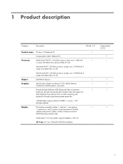
... (UMA) graphics subsystem Broadcom High Definition (HD) Enhanced Video Accelerator √ hardware decoder (on-board) (select models only) and support for DVD playback from external drive or Flash streaming and playback of locally-stored downloaded media files 128-MB buffer memory (64M×16 DDR3 × 1 piece, 1.5V/ 800MHz DRAM) Display The display assembly includes 1 webcam, 1 microphone, √ 1 speaker box, and 2 wireless local-area network (WLAN) antenna transceivers/cables;
... (UMA) graphics subsystem Broadcom High Definition (HD) Enhanced Video Accelerator √ hardware decoder (on-board) (select models only) and support for DVD playback from external drive or Flash streaming and playback of locally-stored downloaded media files 128-MB buffer memory (64M×16 DDR3 × 1 piece, 1.5V/ 800MHz DRAM) Display The display assembly includes 1 webcam, 1 microphone, √ 1 speaker box, and 2 wireless local-area network (WLAN) antenna transceivers/cables;

Maintenance and Service Guide
Page 12
... USB Key Recovery support (for correct output to wideaspect vs. includes link and activity lights) USB 2.0 (3) VGA, supporting up to 1600x900 external resolution @ 60 Hz, hot plug/unplug, and auto detection for Service, refurbish centers, and repair centers) Linux √ FreeDOS √ √ Serviceability End-user replaceable parts: √ √ AC adapter Battery (system) Hard drive Memory module WLAN module or WLAN+Bluetooth module WWAN module (select models only) GPS module (select models only) Keyboard √ 4 Chapter 1 Product description Ports Audio...
... USB Key Recovery support (for correct output to wideaspect vs. includes link and activity lights) USB 2.0 (3) VGA, supporting up to 1600x900 external resolution @ 60 Hz, hot plug/unplug, and auto detection for Service, refurbish centers, and repair centers) Linux √ FreeDOS √ √ Serviceability End-user replaceable parts: √ √ AC adapter Battery (system) Hard drive Memory module WLAN module or WLAN+Bluetooth module WWAN module (select models only) GPS module (select models only) Keyboard √ 4 Chapter 1 Product description Ports Audio...

Maintenance and Service Guide
Page 14
Top components TouchPad Component Description (1) TouchPad zone Moves the pointer and selects or activates items on the screen. (2) TouchPad button* Functions like the left and right buttons on an external mouse. *This table describes factory settings. To view or change pointing device preferences, select Start > Devices and Printers. Then, right-click the icon representing your device, and select Mouse settings. 6 Chapter 2 External component identification
Top components TouchPad Component Description (1) TouchPad zone Moves the pointer and selects or activates items on the screen. (2) TouchPad button* Functions like the left and right buttons on an external mouse. *This table describes factory settings. To view or change pointing device preferences, select Start > Devices and Printers. Then, right-click the icon representing your device, and select Mouse settings. 6 Chapter 2 External component identification

Maintenance and Service Guide
Page 17
... , slide the switch to turn on the computer. ● When the computer is on . ● Blinking white: The computer is in the Sleep state. ● Off: The computer is off or in Hibernation, briefly slide the switch to exit Hibernation. Right-side components Component (1) Digital Media Slot (2) Power light (3) Power switch (4) USB ports (2) Description Supports the following optional digital card formats: ● Memory Stick ● Memory Stick Pro ● MultiMediaCard...
... , slide the switch to turn on the computer. ● When the computer is on . ● Blinking white: The computer is in the Sleep state. ● Off: The computer is off or in Hibernation, briefly slide the switch to exit Hibernation. Right-side components Component (1) Digital Media Slot (2) Power light (3) Power switch (4) USB ports (2) Description Supports the following optional digital card formats: ● Memory Stick ● Memory Stick Pro ● MultiMediaCard...

Maintenance and Service Guide
Page 18
... computer fan starts up automatically to cool internal components. Enables airflow to cool internal components and prevent overheating. Component (5) Security cable slot (6) RJ-45 (network) jack and cover Left-side components Description Attaches an optional security cable to cycle on battery power. ● Blinking white: The battery has reached a low battery level, a critical battery level, or there is designed to external power and the battery is idle. 10 Chapter 2 External component identification Connects a network cable...
... computer fan starts up automatically to cool internal components. Enables airflow to cool internal components and prevent overheating. Component (5) Security cable slot (6) RJ-45 (network) jack and cover Left-side components Description Attaches an optional security cable to cycle on battery power. ● Blinking white: The battery has reached a low battery level, a critical battery level, or there is designed to external power and the battery is idle. 10 Chapter 2 External component identification Connects a network cable...
Maintenance and Service Guide
Page 31
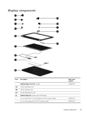
Display components Item Description (1a) (1b) (1c) (2) Display Hinge Cover Kit, includes: Left and right hinge covers Left and right hinge caps Left and right hinge cap wall Display Hinge Kit (includes right and left hinges) For use with HP Mini 110 and Compaq Mini CQ10 computer models For use with Compaq Mini CQ10 LTE computer models Spare part number 633483-001 633482-001 638232-001 Display components 23
Display components Item Description (1a) (1b) (1c) (2) Display Hinge Cover Kit, includes: Left and right hinge covers Left and right hinge caps Left and right hinge cap wall Display Hinge Kit (includes right and left hinges) For use with HP Mini 110 and Compaq Mini CQ10 computer models For use with Compaq Mini CQ10 LTE computer models Spare part number 633483-001 633482-001 638232-001 Display components 23
Maintenance and Service Guide
Page 36
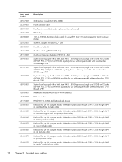
... 633476-051 633476-061 633476-071 633476-121 Description 2-GB memory module (667-MHz, DDR3): Power connector cable Fan/heat sink assembly (includes replacement thermal material) RTC battery 10.1-in, WSVGA, AntiGlare display panel for use with HP Mini 110 and Compaq Mini CQ10 computer models 40-W AC adapter, non-Smart RC/V 2W Hard Drive Cable Kit 3-cell Li-ion battery (28-WH 2.55-Ahr) 6-cell Li-ion high-capacity...
... 633476-051 633476-061 633476-071 633476-121 Description 2-GB memory module (667-MHz, DDR3): Power connector cable Fan/heat sink assembly (includes replacement thermal material) RTC battery 10.1-in, WSVGA, AntiGlare display panel for use with HP Mini 110 and Compaq Mini CQ10 computer models 40-W AC adapter, non-Smart RC/V 2W Hard Drive Cable Kit 3-cell Li-ion battery (28-WH 2.55-Ahr) 6-cell Li-ion high-capacity...
Maintenance and Service Guide
Page 56
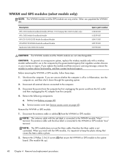
..., replace the wireless module only with the GPS module, it down the computer. Battery (see Service access cover on page 43). Remove the WWAN or GPS module: 1. Shut down through the operating system. 2. When you work with a wireless module authorized for use the Main cable, therefore the Main cable is connected to restore device functionality, and then contact technical support. If you replace the module and then receive a warning message, remove the module to the WWAN module...
..., replace the wireless module only with the GPS module, it down the computer. Battery (see Service access cover on page 43). Remove the WWAN or GPS module: 1. Shut down through the operating system. 2. When you work with a wireless module authorized for use the Main cable, therefore the Main cable is connected to restore device functionality, and then contact technical support. If you replace the module and then receive a warning message, remove the module to the WWAN module...

Maintenance and Service Guide
Page 58
... operating system. 2. b. Remove the 2 Phillips 2.0×3.0 screws (2) that regulates wireless devices in your country or region. CAUTION: To prevent an unresponsive system, replace the wireless module only with the white label is connected to the system board. (The WLAN module tilts up.) 50 Chapter 4 Removal and replacement procedures Before removing the WLAN module, follow these steps: 1. Disconnect the WLAN antenna cables (1) from the computer. 4. Battery (see Service access cover...
... operating system. 2. b. Remove the 2 Phillips 2.0×3.0 screws (2) that regulates wireless devices in your country or region. CAUTION: To prevent an unresponsive system, replace the wireless module only with the white label is connected to the system board. (The WLAN module tilts up.) 50 Chapter 4 Removal and replacement procedures Before removing the WLAN module, follow these steps: 1. Disconnect the WLAN antenna cables (1) from the computer. 4. Battery (see Service access cover...
Maintenance and Service Guide
Page 69
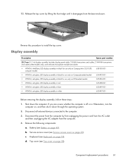
...). Keyboard (see Top cover on , and then shut it disengages from the computer by lifting the front edge until it down the computer. c. d. Display assembly Description Spare part number 25.7-cm (10.1-in) display assembly (includes display panel cable, 2 WLAN transceivers and cables, 2 WWAN transceivers and cables (select models only), and webcam/microphone module and cable): ● WSVGA, AntiGlare, LED display assembly in black for use only on Compaq Mini CQ10 LTE computer models...
...). Keyboard (see Top cover on , and then shut it disengages from the computer by lifting the front edge until it down the computer. c. d. Display assembly Description Spare part number 25.7-cm (10.1-in) display assembly (includes display panel cable, 2 WLAN transceivers and cables, 2 WWAN transceivers and cables (select models only), and webcam/microphone module and cable): ● WSVGA, AntiGlare, LED display assembly in black for use only on Compaq Mini CQ10 LTE computer models...
Maintenance and Service Guide
Page 80
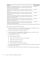
... by first unplugging the power cord from the AC outlet and then unplugging the AC adapter from the WWAN module (see Keyboard on , and then shut it down the computer. Keyboard (see WWAN and GPS modules (select models only) on page 50). 72 Chapter 4 Removal and replacement procedures d. Disconnect all external devices connected to the computer. 3. Description Spare part number Equipped with an Intel...
... by first unplugging the power cord from the AC outlet and then unplugging the AC adapter from the WWAN module (see Keyboard on , and then shut it down the computer. Keyboard (see WWAN and GPS modules (select models only) on page 50). 72 Chapter 4 Removal and replacement procedures d. Disconnect all external devices connected to the computer. 3. Description Spare part number Equipped with an Intel...

Maintenance and Service Guide
Page 85
... "F10 = BIOS Setup Options" message is not working. Use the arrow keys to select System Configuration > Language, and then press enter. 3. When a confirmation prompt with your change and exit Setup Utility, use the arrow keys to change goes into effect immediately. Starting Setup Utility 77 If Setup Utility is already running , begin at step 1. 5 Setup Utility Starting Setup Utility Setup Utility is a ROM-based information and customization utility that can be used even when your Windows operating system is displayed in the...
... "F10 = BIOS Setup Options" message is not working. Use the arrow keys to select System Configuration > Language, and then press enter. 3. When a confirmation prompt with your change and exit Setup Utility, use the arrow keys to change goes into effect immediately. Starting Setup Utility 77 If Setup Utility is already running , begin at step 1. 5 Setup Utility Starting Setup Utility Setup Utility is a ROM-based information and customization utility that can be used even when your Windows operating system is displayed in the...
Maintenance and Service Guide
Page 86
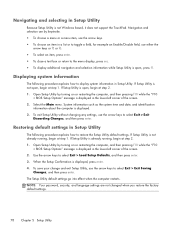
... > Exit Discarding Changes, and then press enter. Select the Main menu. To save your change and exit Setup Utility, use the arrow keys to the menu display, press esc. ● To display additional navigation and selection information while Setup Utility is open , press f1. To exit Setup Utility without changing any settings, use the arrow keys to restore the Setup Utility default settings. Use the arrow keys to toggle a field, for example an Enable/Disable field, use the arrow keys. ●...
... > Exit Discarding Changes, and then press enter. Select the Main menu. To save your change and exit Setup Utility, use the arrow keys to the menu display, press esc. ● To display additional navigation and selection information while Setup Utility is open , press f1. To exit Setup Utility without changing any settings, use the arrow keys to restore the Setup Utility default settings. Use the arrow keys to toggle a field, for example an Enable/Disable field, use the arrow keys. ●...

Maintenance and Service Guide
Page 88
...; Internal hard drive (select models only) ◦ USB floppy ◦ USB CD/DVD ROM drive ◦ USB flash drive ◦ USB Hard drive ◦ USB Card reader ◦ Network adapter NOTE: Only the devices attached to the system appear in the boot order menu. To do this Run a comprehensive self-test on the system memory. 80 Chapter 5 Setup Utility Select Processor C4 State Boot Options Diagnostics menu Select Hard Disk Self Test (select models only) Memory Test To do this Enable/disable the processor C4 sleep state...
...; Internal hard drive (select models only) ◦ USB floppy ◦ USB CD/DVD ROM drive ◦ USB flash drive ◦ USB Hard drive ◦ USB Card reader ◦ Network adapter NOTE: Only the devices attached to the system appear in the boot order menu. To do this Run a comprehensive self-test on the system memory. 80 Chapter 5 Setup Utility Select Processor C4 State Boot Options Diagnostics menu Select Hard Disk Self Test (select models only) Memory Test To do this Enable/disable the processor C4 sleep state...

Maintenance and Service Guide
Page 92
... most recent backup. As you add new software and data files, you can use an external optical drive, it in case of a computer failure: ● Creating a set of a recovery partition, click Start, right-click Computer, click Manage, and then click Disk Management. Handle these discs after software setup. If you create recovery discs immediately after setting up your information ● Creating system restore points ● Recovering a program or driver ● Performing a full system recovery (from the...
... most recent backup. As you add new software and data files, you can use an external optical drive, it in case of a computer failure: ● Creating a set of a recovery partition, click Start, right-click Computer, click Manage, and then click Disk Management. Handle these discs after software setup. If you create recovery discs immediately after setting up your information ● Creating system restore points ● Recovering a program or driver ● Performing a full system recovery (from the...

Maintenance and Service Guide
Page 93
... the Recovery Manager software. ● The computer must be required, whereas only a few DVDs or BDs are required. This type of recovery restores the computer to its own built-in repair features, such as System Restore. To create a set up the computer. ● Windows has its original factory state. Recovery Manager works from recovery discs or from a dedicated recovery partition (select models only) on -screen instructions. Performing a system recovery 85 If you use CDs, up . Recovering using...
... the Recovery Manager software. ● The computer must be required, whereas only a few DVDs or BDs are required. This type of recovery restores the computer to its own built-in repair features, such as System Restore. To create a set up the computer. ● Windows has its original factory state. Recovery Manager works from recovery discs or from a dedicated recovery partition (select models only) on -screen instructions. Performing a system recovery 85 If you use CDs, up . Recovering using...
Maintenance and Service Guide
Page 106
... boot order 80 caps lock light, identifying 7 changing Setup Utility language 77 chipset, product description 1 components additional hardware 15 bottom 13 computer, major 17 display 12 front 8 left-side 10 right-side 9 TouchPad 6 computer feet locations 39 spare part number 39 connector, power 10 connectors, service considerations 35 cord, power 15 D device specifications 81 devices, mass storage 25 Diagnostics menu 80 Digital Media Slot, identifying 9 diskette drive, precautions 35 display product description 1 removal 61 spare part numbers...
... boot order 80 caps lock light, identifying 7 changing Setup Utility language 77 chipset, product description 1 components additional hardware 15 bottom 13 computer, major 17 display 12 front 8 left-side 10 right-side 9 TouchPad 6 computer feet locations 39 spare part number 39 connector, power 10 connectors, service considerations 35 cord, power 15 D device specifications 81 devices, mass storage 25 Diagnostics menu 80 Digital Media Slot, identifying 9 diskette drive, precautions 35 display product description 1 removal 61 spare part numbers...
Maintenance and Service Guide
Page 107
... webcam light, identifying 12 internal display switch, identifying 12 internal media cards, product description 3 internal microphone, identifying 12 J jacks audio-in (microphone) 11 audio-out (headphone) 11 RJ-45 (network) 10 K keyboard product description 4 removal 55 spare part numbers 18, 28, 29, 31, 32, 33, 55 keys action 8 esc 8 fn 8 Windows applications 8 Windows logo 8 L language support 79 latch, battery release 13 lights battery 10 caps lock 7 power 9 webcam 12 M Main menu 79 mass storage devices, hard drive 25 memory module product description 2 removal 52 spare part numbers...
... webcam light, identifying 12 internal display switch, identifying 12 internal media cards, product description 3 internal microphone, identifying 12 J jacks audio-in (microphone) 11 audio-out (headphone) 11 RJ-45 (network) 10 K keyboard product description 4 removal 55 spare part numbers 18, 28, 29, 31, 32, 33, 55 keys action 8 esc 8 fn 8 Windows applications 8 Windows logo 8 L language support 79 latch, battery release 13 lights battery 10 caps lock 7 power 9 webcam 12 M Main menu 79 mass storage devices, hard drive 25 memory module product description 2 removal 52 spare part numbers...

Maintenance and Service Guide
Page 108
... drive 2 internal media cards 3 keyboard 4 memory module 2 modem 2 operating system 4 optical drive 2 pointing device 4 ports 4 power requirements 4 processors 1 product name 1 security 4 serviceability 4 video 2 wireless 3 product name 1 R recovering a program or driver 84 recovering from the dedicated recovery partition 85 recovering from the recovery discs 87 recovery discs 84 Recovery Manager 84, 85 recovery partition 84 recovery, system 85 recycling battery 92 display 92 removal/replacement preliminaries 34 procedures 39 restore points 89 restoring default settings 78 RJ-45 (network) jack...
... drive 2 internal media cards 3 keyboard 4 memory module 2 modem 2 operating system 4 optical drive 2 pointing device 4 ports 4 power requirements 4 processors 1 product name 1 security 4 serviceability 4 video 2 wireless 3 product name 1 R recovering a program or driver 84 recovering from the dedicated recovery partition 85 recovering from the recovery discs 87 recovery discs 84 Recovery Manager 84, 85 recovery partition 84 recovery, system 85 recycling battery 92 display 92 removal/replacement preliminaries 34 procedures 39 restore points 89 restoring default settings 78 RJ-45 (network) jack...


