
Owners Manual
Page 3
... jewelry that might get caught in cord. Always Avoid Accidental Staring. Check for proper blade size and type for thickness and type of time. 10. Make sure that does not have a flat surface, unless a suitable support is accidentally contacted. _ I_, Always Disconnect Tools. Note and...tipped or if the cutting tool is used for the best footing. Disconnect tools before cutting long curves. 9. Make sure switch is to saw will operate properly and perform its intended function. Never attempt to be used . 4. Always stop the Bandsaw before plugging in moving ir...
... jewelry that might get caught in cord. Always Avoid Accidental Staring. Check for proper blade size and type for thickness and type of time. 10. Make sure that does not have a flat surface, unless a suitable support is accidentally contacted. _ I_, Always Disconnect Tools. Note and...tipped or if the cutting tool is used for the best footing. Disconnect tools before cutting long curves. 9. Make sure switch is to saw will operate properly and perform its intended function. Never attempt to be used . 4. Always stop the Bandsaw before plugging in moving ir...
Owners Manual
Page 4
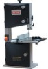
...from the bag of the table (See Fig. 1). Remove the protective oil that is applied to the upper table trunnion, taking care when passing the saw blade through the slot of loose parts. Main Machine 1 Fence Assembly 1 Table 1 Guide Rail 1 Owner's Manual 1 Upper Table Trunnion Assembly 1 ...Bag of paste wax to the table to be installed: Table, Blade Tension Knob and Rip Fence. UNPACKING AND CHECKING CONTENTS Model 119.214000 10" Bandsaw is supplied partly assembled. Socket Head Cap Screw M6x30 1 Washer6 1 Wing Nut M6 1 Hex. a. Assemble the upper table trunnion to...
...from the bag of the table (See Fig. 1). Remove the protective oil that is applied to the upper table trunnion, taking care when passing the saw blade through the slot of loose parts. Main Machine 1 Fence Assembly 1 Table 1 Guide Rail 1 Owner's Manual 1 Upper Table Trunnion Assembly 1 ...Bag of paste wax to the table to be installed: Table, Blade Tension Knob and Rip Fence. UNPACKING AND CHECKING CONTENTS Model 119.214000 10" Bandsaw is supplied partly assembled. Socket Head Cap Screw M6x30 1 Washer6 1 Wing Nut M6 1 Hex. a. Assemble the upper table trunnion to...

Owners Manual
Page 5
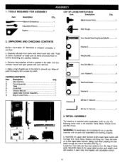
b. To ensure sufficient upright stability of the machine it should be bolted to the saw blade. FIG. 6 tension knob =g knob ]uide T _. _ _Blade rack ng knob 'Guide post adjusting knob , Lower tabl Dust Tighten rip fence handle by pressing downward. (See ...
b. To ensure sufficient upright stability of the machine it should be bolted to the saw blade. FIG. 6 tension knob =g knob ]uide T _. _ _Blade rack ng knob 'Guide post adjusting knob , Lower tabl Dust Tighten rip fence handle by pressing downward. (See ...
Owners Manual
Page 6
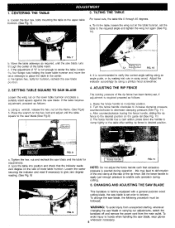
... the table tilts 0 through the center of the table insert. FIG, 7 b, Move the table sideways as required, until the table square to the saw blade.(See Fig.8) FIG. 10 b. c. It is exerted during cutting. 5. Raise the fence handle to give zero degree reading. (See Fig. 9) I FIG. Lock the table ...remove the power cord from the main outlet. To avoid injury to the required angle and tighten the wing nut again (See Fig. 10). bolt and adjust until the saw blade. b. Set the fence handle to apply just enough pressure to the upper table trunnion. (See Fig. 7) 3. ADJUSTING THE ...
... the table tilts 0 through the center of the table insert. FIG, 7 b, Move the table sideways as required, until the table square to the saw blade.(See Fig.8) FIG. 10 b. c. It is exerted during cutting. 5. Raise the fence handle to give zero degree reading. (See Fig. 9) I FIG. Lock the table ...remove the power cord from the main outlet. To avoid injury to the required angle and tighten the wing nut again (See Fig. 10). bolt and adjust until the saw blade. b. Set the fence handle to apply just enough pressure to the upper table trunnion. (See Fig. 7) 3. ADJUSTING THE ...

Owners Manual
Page 7
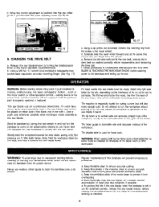
... thetopoftheuppewr heehl ousincgounterclockwuinsteilthesaw bladehasslackene(dviewefdromabove()SeeFig.12). When the correct adjustment is installed and tensioned, track the saw blade. b. Do not set as close as practical against the workpiece. Setthebladeguidetotherequirehdeighbt yturnintgheguide postadjustinkgnob. ADJUSTING THE BLADE GUIDES d....unlocking the guide adjusting screw (D) Fig, 16 7 Adjust the rear roller guide to within 1/32" of the saw blade by turning the door locking knobs before setting the blade guides. To adjust the upper blade guides, first ...
... thetopoftheuppewr heehl ousincgounterclockwuinsteilthesaw bladehasslackene(dviewefdromabove()SeeFig.12). When the correct adjustment is installed and tensioned, track the saw blade. b. Do not set as close as practical against the workpiece. Setthebladeguidetotherequirehdeighbt yturnintgheguide postadjustinkgnob. ADJUSTING THE BLADE GUIDES d....unlocking the guide adjusting screw (D) Fig, 16 7 Adjust the rear roller guide to within 1/32" of the saw blade by turning the door locking knobs before setting the blade guides. To adjust the upper blade guides, first ...
Owners Manual
Page 8
...the workpiece. CHANGING THE DRIVE BELT a. Follow procedures for cutting curves, but will prevent unnecessary problems. a. Never use . The saw blade cuts on either side of bandsaw counterclockwise. The rip fence is reached, lock the rear roller guide in use for use ...adjusting screw (C) 9. b. The machine is used for cutting sharp curves. The tiltable table is especially suited for CHANGING AND ADJUSTING THE SAW BLADE & TRACKING THE BANDSAW BLADE, before reassembling and tensioning the drive belt) f. Remove the old drive belt and fit the new ...
...the workpiece. CHANGING THE DRIVE BELT a. Follow procedures for cutting curves, but will prevent unnecessary problems. a. Never use . The saw blade cuts on either side of bandsaw counterclockwise. The rip fence is reached, lock the rear roller guide in use for use ...adjusting screw (C) 9. b. The machine is used for cutting sharp curves. The tiltable table is especially suited for CHANGING AND ADJUSTING THE SAW BLADE & TRACKING THE BANDSAW BLADE, before reassembling and tensioning the drive belt) f. Remove the old drive belt and fit the new ...
Owners Manual
Page 9
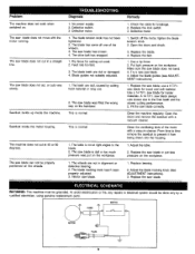
...Clean the ventilating slots of the wheels. 3. To avoid electrocution or fire, any repairs to prevent it from being drawn into the housing. 1. The saw blade does not cut , or cuts very slowly. Rip fence for wood and soft material. Open the doors and check. 3. Put light pressure on ... or damaged. 4, Blade guides not suitably adjusted. 1. Switch off one of the motor with a vacuum cleaner. Use a rip fence. 2. Make sure the saw blade does not cut in alignment or defective bearing. 2. SWITCH I MOTOR PLUG _L Feed rate too fast. 3. This is normal This is dull or too...
...Clean the ventilating slots of the wheels. 3. To avoid electrocution or fire, any repairs to prevent it from being drawn into the housing. 1. The saw blade does not cut , or cuts very slowly. Rip fence for wood and soft material. Open the doors and check. 3. Put light pressure on ... or damaged. 4, Blade guides not suitably adjusted. 1. Switch off one of the motor with a vacuum cleaner. Use a rip fence. 2. Make sure the saw blade does not cut in alignment or defective bearing. 2. SWITCH I MOTOR PLUG _L Feed rate too fast. 3. This is normal This is dull or too...

Owners Manual
Page 11
...163 11 DESCRIPTION • Flat Countersunk Rod Guide Guide Rail Fence Carrier Head Screw M6x1O ,Special Screw Washer 10 Fence Handle Roll Pin 3x18 Star knob screw Washer 6 Aluminium Bar Miter Gauge Base Indicator Pan Head Screw M5x6...Hex, Bolt M6x35 Hex. Bolt M6x45 Door locking knob body Hex. Nut M6 Slotted Insert Special Spring Washer 10 Lock Housing Upper Door Rivet 4x8 Leaf Spring Special Nut M22 Tongue Lock Spring Washer 6 Lock Nut M6 ...Ball Bearing 12ram Retaining Ring 28 Lower Wheel Tire Retaining Ring 12 Saw Blade Upper Wheel Upper Bearing Bolt Wheel Carrier Bracket Hex.
...163 11 DESCRIPTION • Flat Countersunk Rod Guide Guide Rail Fence Carrier Head Screw M6x1O ,Special Screw Washer 10 Fence Handle Roll Pin 3x18 Star knob screw Washer 6 Aluminium Bar Miter Gauge Base Indicator Pan Head Screw M5x6...Hex, Bolt M6x35 Hex. Bolt M6x45 Door locking knob body Hex. Nut M6 Slotted Insert Special Spring Washer 10 Lock Housing Upper Door Rivet 4x8 Leaf Spring Special Nut M22 Tongue Lock Spring Washer 6 Lock Nut M6 ...Ball Bearing 12ram Retaining Ring 28 Lower Wheel Tire Retaining Ring 12 Saw Blade Upper Wheel Upper Bearing Bolt Wheel Carrier Bracket Hex.


