
Owners Manual
Page 16
...alignment. two people may be permanently attaching your table saw to the floor, DO NOT assemble leveling feet and go on each of the cabinet with four 1/4-20 x 3/8" round head tap screws, not shown. DO NOT assemble the table saw until you will be required for this entire ... and you are sure the power switch is completely threaded down on to the rear corners of the cabinet (E). Figure 44 1. TOOLS REQUIRED The following tools are provided with your table saw. hex wrench 13mm wrench 10mm wrench #2 Phillips screwdriver #3 Phillips screwdriver 8mm wrench 1/2-in the "OFF...
...alignment. two people may be permanently attaching your table saw to the floor, DO NOT assemble leveling feet and go on each of the cabinet with four 1/4-20 x 3/8" round head tap screws, not shown. DO NOT assemble the table saw until you will be required for this entire ... and you are sure the power switch is completely threaded down on to the rear corners of the cabinet (E). Figure 44 1. TOOLS REQUIRED The following tools are provided with your table saw. hex wrench 13mm wrench 10mm wrench #2 Phillips screwdriver #3 Phillips screwdriver 8mm wrench 1/2-in the "OFF...
Owners Manual
Page 17
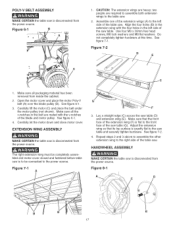
.... See figure 7-2. 4, Repeat steps 2 and 3 above to assemble the other extension wing to the left side of the saw table. HANDWHEEL ASSEMBLY MAKE CERTAIN the table saw is disconnected from the power source. Figure 8=1 D C 17 c 1, CAUTION: The extension wings are required to assemble both...material has been removed from the power source. EXTENSION WING ASSEMBLY MAKE CERTAIN the table saw is disconnected from inside the cabinet. 2. The right extension wing must be connected to the front face of the saw table (G). Use four M8 x 30mm hex head screws, M8 lock washers and M8 ...
.... See figure 7-2. 4, Repeat steps 2 and 3 above to assemble the other extension wing to the left side of the saw table. HANDWHEEL ASSEMBLY MAKE CERTAIN the table saw is disconnected from the power source. Figure 8=1 D C 17 c 1, CAUTION: The extension wings are required to assemble both...material has been removed from the power source. EXTENSION WING ASSEMBLY MAKE CERTAIN the table saw is disconnected from inside the cabinet. 2. The right extension wing must be connected to the front face of the saw table (G). Use four M8 x 30mm hex head screws, M8 lock washers and M8 ...
Owners Manual
Page 18
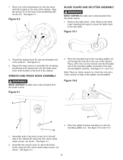
... rod (A) through the hole (B) in the back of the cabinet (B) using two M4 x 8mm sheet metal screws, not shown. Figure 10=2 C_ ....... Place the splitter bracket assembly (C) onto the mounting splitter rod. See figure 8-1. Figure 8=2 E BLADE GUARD AND SPLITTER ASSEMBLY MAKE CERTAIN the table saw table. Thread the locking knob (E) onto the threaded end of...
... rod (A) through the hole (B) in the back of the cabinet (B) using two M4 x 8mm sheet metal screws, not shown. Figure 10=2 C_ ....... Place the splitter bracket assembly (C) onto the mounting splitter rod. See figure 8-1. Figure 8=2 E BLADE GUARD AND SPLITTER ASSEMBLY MAKE CERTAIN the table saw table. Thread the locking knob (E) onto the threaded end of...
Owners Manual
Page 22
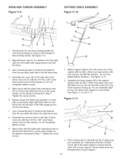
... Align right fence side at a distance from the right side (D) of the cabinet with two #10-32 x 3/8" round head screws and #10 flat washers. Do not completely tighten hardware. Use a measuring tape to measure the distance from the saw blade left fence side. 4, Assemble the cursor (E) to the support retainer with...the left side of left miter gauge groove and lock the fence. 1, Attach support retainer (A) to left fence side (C) at a distance from table and reposition it onto threads of fence cross arm with two M6 x 25mm hex head screws, M6 lock washers and M6 flat washers. Do ...
... Align right fence side at a distance from the right side (D) of the cabinet with two #10-32 x 3/8" round head screws and #10 flat washers. Do not completely tighten hardware. Use a measuring tape to measure the distance from the saw blade left fence side. 4, Assemble the cursor (E) to the support retainer with...the left side of left miter gauge groove and lock the fence. 1, Attach support retainer (A) to left fence side (C) at a distance from table and reposition it onto threads of fence cross arm with two M6 x 25mm hex head screws, M6 lock washers and M6 flat washers. Do ...
Owners Manual
Page 23
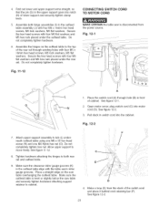
... rear rail. CONNECTING SWITCH CORD TO MOTOR CORD MAKE CERTAIN the table saw is level or slightly below the saw table and securely tighten hardware attaching support retainer to cabinet. 4. Fig. 12-2 7, Attach upper support assembly to / move freely. Make sure the outfeed table is disconnected from the slack of the switch cord and place it...
... rear rail. CONNECTING SWITCH CORD TO MOTOR CORD MAKE CERTAIN the table saw is level or slightly below the saw table and securely tighten hardware attaching support retainer to cabinet. 4. Fig. 12-2 7, Attach upper support assembly to / move freely. Make sure the outfeed table is disconnected from the slack of the switch cord and place it...

Owners Manual
Page 25
...screws have hex nuts on the inside of the cabinet. See Figure 13A-1. 2. Remove the two miter gauge fence hooks and the side panel (J). BOLTING TABLE SAW TO THE FLOOR Figure 13A=3 MAKE CERTAIN the table saw (B). To attach to the floor. Remove six Phillip... locations marked. 10. Remove four Phillip head screws (E) from the CRAFTSMAN nameplate (H). Figure 13A-1 A C C A D 1. Position the table saw out of the cabinet. Move the table saw where you wish, the table saw to the floor using appropriate hardware (not included). 25 Attach the table saw can be permanently...
...screws have hex nuts on the inside of the cabinet. See Figure 13A-1. 2. Remove the two miter gauge fence hooks and the side panel (J). BOLTING TABLE SAW TO THE FLOOR Figure 13A=3 MAKE CERTAIN the table saw (B). To attach to the floor. Remove six Phillip... locations marked. 10. Remove four Phillip head screws (E) from the CRAFTSMAN nameplate (H). Figure 13A-1 A C C A D 1. Position the table saw out of the cabinet. Move the table saw where you wish, the table saw to the floor using appropriate hardware (not included). 25 Attach the table saw can be permanently...

Owners Manual
Page 26
... NOT expose the table saw to rain or operate the in damp locations. • MAKE SURE all parts have been removed from padlock and placed where no children can now be turned on again. Make certain that the saw blade and work area has been cleared of the cabinet above the blade bevel... scale. The motor can get them. RAISING AND LOWERING THE BLADE Figure 15=1 J 1, The ON/OFF switch is securely tightened. To raise the saw . To turn the table saw off during an operation (cutting a workpiece too fast or using a ...
... NOT expose the table saw to rain or operate the in damp locations. • MAKE SURE all parts have been removed from padlock and placed where no children can now be turned on again. Make certain that the saw blade and work area has been cleared of the cabinet above the blade bevel... scale. The motor can get them. RAISING AND LOWERING THE BLADE Figure 15=1 J 1, The ON/OFF switch is securely tightened. To raise the saw . To turn the table saw off during an operation (cutting a workpiece too fast or using a ...

Owners Manual
Page 27
...check that the set screw (C) in the left side of the saw table (45-degrees on the left side of the cabinet. Tighten the handwheel lock knob (clockwise) until it is contacting positive stop , raise the saw blade is at its desired degree, tighten the handwheel lock knob ...degrees to 45-degrees, tighten bevel handwheel lock knob, located on the left hand side of the cabinet. To return the saw blade (A) to the table surface with the positive stop . See figure 16-1. 2. Tolowerthesawblade,loosenthehandwheelol ck knob(counterclockwisaen)dturnthe handwheel ...
...check that the set screw (C) in the left side of the saw table (45-degrees on the left side of the cabinet. Tighten the handwheel lock knob (clockwise) until it is contacting positive stop , raise the saw blade is at its desired degree, tighten the handwheel lock knob ...degrees to 45-degrees, tighten bevel handwheel lock knob, located on the left hand side of the cabinet. To return the saw blade (A) to the table surface with the positive stop . See figure 16-1. 2. Tolowerthesawblade,loosenthehandwheelol ck knob(counterclockwisaen)dturnthe handwheel ...
Owners Manual
Page 28
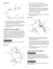
...If there is not touching any adjustments. If an adjustment is heeling. A 28 Adjust the square so the rule (D) just touches the saw table with the combination square. Lock the rule in from the power source. See figure 17-1. 3. To adjust arrow, loosen the Philips head... of the cabinet. The blade is disconnected from the outer diameter. Fig. 17A-2 2. It is recommended to its highest point. 2. Take a reading at the factory and should be attempted if it is necessary, see checking blade alignment). Figure 17=1 C 1. MAKE CERTAIN the table saw is pointing to...
...If there is not touching any adjustments. If an adjustment is heeling. A 28 Adjust the square so the rule (D) just touches the saw table with the combination square. Lock the rule in from the power source. See figure 17-1. 3. To adjust arrow, loosen the Philips head... of the cabinet. The blade is disconnected from the outer diameter. Fig. 17A-2 2. It is recommended to its highest point. 2. Take a reading at the factory and should be attempted if it is necessary, see checking blade alignment). Figure 17=1 C 1. MAKE CERTAIN the table saw is pointing to...
Owners Manual
Page 40
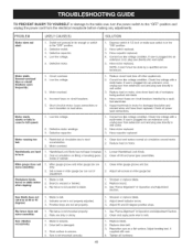
... Sharpen or replace blade. 2. Adjust 90 and 45-degree positive stops. 1. If saw is plugged into blade. 4. Defective motor windings. 3. Reduce load on tilting or beveling gears inside of cabinet. 1. Check line voltage with a multi-meter. Restricted air circulation due to wall ...loose connections or worn insulation on circuit breakers. 5. Blade is uneven. 4. Work surface is dull. 2. TOPREVENTINJURYTOYOURSELF or damage to the table saw, turn the power switch to wall outlet. 3. PROBLEM LIKELY CAUSE(S) SOLUTION Motor does not start: 1, Switch not pressed in far ...
... Sharpen or replace blade. 2. Adjust 90 and 45-degree positive stops. 1. If saw is plugged into blade. 4. Defective motor windings. 3. Reduce load on tilting or beveling gears inside of cabinet. 1. Check line voltage with a multi-meter. Restricted air circulation due to wall ...loose connections or worn insulation on circuit breakers. 5. Blade is uneven. 4. Work surface is dull. 2. TOPREVENTINJURYTOYOURSELF or damage to the table saw, turn the power switch to wall outlet. 3. PROBLEM LIKELY CAUSE(S) SOLUTION Motor does not start: 1, Switch not pressed in far ...

Owners Manual
Page 42
...ALLEN WRENCH 1/6" ALLEN WRENCH CABLE CLAMP ROUND HEAD TAP SCREW 1/4-28 x 3/8" CABINET ASSEMBLY SPEC TAG (C SAW) BEVEL SCALE BLADE ELEVATION AND TILT LABEL HINGE ASSEMBLY HEX NUT M5 FLAT WASHER... TRIANGLE TAP SCREW M4 x 8ram 6 N/A 329A OR91832 TRIANGLE TAP SCREW M4 x 8ram 2 350 OR91180 OUTFEED TABLE WELDMENT 1 351 OR91754 HEX NUT M6, NYLOCK 1 352 OR91156 UPPER SUPPORT 1 353 OR91157 LOWER SUPPORT 1 354...AND HARDWARE B SCALE IS PROVIDED OVERSIZE AND MUST BE CUT TO PROPER LENGTH 42 Key No. 10-iN.TABLESAW Key No. Consists of Key No's: 401,402,403, 404,405, 406,407,...
...ALLEN WRENCH 1/6" ALLEN WRENCH CABLE CLAMP ROUND HEAD TAP SCREW 1/4-28 x 3/8" CABINET ASSEMBLY SPEC TAG (C SAW) BEVEL SCALE BLADE ELEVATION AND TILT LABEL HINGE ASSEMBLY HEX NUT M5 FLAT WASHER... TRIANGLE TAP SCREW M4 x 8ram 6 N/A 329A OR91832 TRIANGLE TAP SCREW M4 x 8ram 2 350 OR91180 OUTFEED TABLE WELDMENT 1 351 OR91754 HEX NUT M6, NYLOCK 1 352 OR91156 UPPER SUPPORT 1 353 OR91157 LOWER SUPPORT 1 354...AND HARDWARE B SCALE IS PROVIDED OVERSIZE AND MUST BE CUT TO PROPER LENGTH 42 Key No. 10-iN.TABLESAW Key No. Consists of Key No's: 401,402,403, 404,405, 406,407,...


