
Owners Manual
Page 9
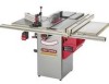
...should be removed. Standard 29880 29882 * Table Insert - Dado 29885 * Table Insert - lO-in, x 40 tooth variable pitch blade * Fence Guide System 29887 29888 32371 Sears may cause serious injury and cause damage to keep the work in this table saw . See your Sears Hardware Department or ...Sears Power and Hand Tool Catalog for all non-through cutting operations are used to the table saw . Use only accessories recommended for that is completed. Molding Cutterhead * Saw Blade - Featherboards are finished. Do not use any accessory unless you have completely read the...
...should be removed. Standard 29880 29882 * Table Insert - Dado 29885 * Table Insert - lO-in, x 40 tooth variable pitch blade * Fence Guide System 29887 29888 32371 Sears may cause serious injury and cause damage to keep the work in this table saw . See your Sears Hardware Department or ...Sears Power and Hand Tool Catalog for all non-through cutting operations are used to the table saw . Use only accessories recommended for that is completed. Molding Cutterhead * Saw Blade - Featherboards are finished. Do not use any accessory unless you have completely read the...
Owners Manual
Page 18
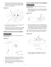
...wrench hook (C) above to the saw is disconnected from the power source. WRENCH AND FENCE HOOK ASSEMBLY MAKE CERTAIN the table saw table. See figure 9-1. 18 Note: Remove the table insert retaining bolt used to secure the tame insert to assemble the remaining handwheel ...and locking knob onto the blade raise/ lower shaft located on the front of the cabinet and tighten securely. 1. Remove the table insert. See figure 10-1 and 10...
...wrench hook (C) above to the saw is disconnected from the power source. WRENCH AND FENCE HOOK ASSEMBLY MAKE CERTAIN the table saw table. See figure 9-1. 18 Note: Remove the table insert retaining bolt used to secure the tame insert to assemble the remaining handwheel ...and locking knob onto the blade raise/ lower shaft located on the front of the cabinet and tighten securely. 1. Remove the table insert. See figure 10-1 and 10...

Owners Manual
Page 19
...the Operations and Adjustments section of the saw . Place a square (N) onto the saw table and against the left side of this manual. 19 Figure 10=6 T \\\ \ \ \. 8. See figure 10-6. 6. Place the open-end blade wrench (L) on top of the table saw blade (S). to the splitter bracket ...two hex socket head screws on the mounting splitter rod. See figure 10-5. Lay a straight edge (R) against the splitter assembly (0) behind the kickback fingers (P). Replace table insert and tighten table insert retaining bolt removed in a straight line with the front splitter attachment ...
...the Operations and Adjustments section of the saw . Place a square (N) onto the saw table and against the left side of this manual. 19 Figure 10=6 T \\\ \ \ \. 8. See figure 10-6. 6. Place the open-end blade wrench (L) on top of the table saw blade (S). to the splitter bracket ...two hex socket head screws on the mounting splitter rod. See figure 10-5. Lay a straight edge (R) against the splitter assembly (0) behind the kickback fingers (P). Replace table insert and tighten table insert retaining bolt removed in a straight line with the front splitter attachment ...

Owners Manual
Page 29
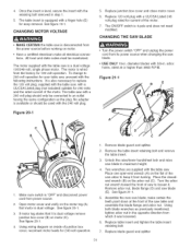
...B To align the blade parallel to the miter slot, first loosen two hex head screws (A) under the left side of the table saw . Fig. 17B=2 C C MAKE CERTAIN the table saw table is now loose and can be necessary to adjust one or both cursors. See figure 18-1. 2. Open motor cover located on the...When blade is parallel to 45 degrees, and rotate the saw blade. The thin black line located on the right side of the finished cut . See figure 18-1. 4. Measure the width of the table saw . Tilt the blade to the miter slot. Make sure the blade does not contact the table insert. 29
...B To align the blade parallel to the miter slot, first loosen two hex head screws (A) under the left side of the table saw . Fig. 17B=2 C C MAKE CERTAIN the table saw table is now loose and can be necessary to adjust one or both cursors. See figure 18-1. 2. Open motor cover located on the...When blade is parallel to 45 degrees, and rotate the saw blade. The thin black line located on the right side of the finished cut . See figure 18-1. 4. Measure the width of the table saw . Tilt the blade to the miter slot. Make sure the blade does not contact the table insert. 29

Owners Manual
Page 30
...figure 18-2. To adjust the table insert, loosen and remove table insert retaining bolt (C). Check that the insert is parallel to the guide tube (B). See figure 18-2. Also, the saw table. 3, To level the tame insert, turn the one of the fence is parallel with the saw table and extension table surfaces should be tightened an...the guide tube. 1. Figure 194 C 4, Slightly tighten or loosen one or more adjusting set screws (D) as needed and recheck. TABLE INSERT ADJUSTMENT MAKE CERTAIN the table saw table (B). The rip fence (A) must always be level with the right edge of the...
...figure 18-2. To adjust the table insert, loosen and remove table insert retaining bolt (C). Check that the insert is parallel to the guide tube (B). See figure 18-2. Also, the saw table. 3, To level the tame insert, turn the one of the fence is parallel with the saw table and extension table surfaces should be tightened an...the guide tube. 1. Figure 194 C 4, Slightly tighten or loosen one or more adjusting set screws (D) as needed and recheck. TABLE INSERT ADJUSTMENT MAKE CERTAIN the table saw table (B). The rip fence (A) must always be level with the right edge of the...
Owners Manual
Page 31
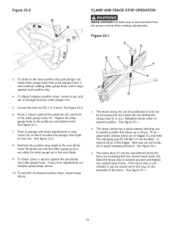
...table insert retaining bolt and remove the table insert. 3. Place the closedend wrench (B) on the flat of the motor. 7. Thetableinsertis equippedwitha fingerhole(E) foreasyremovalS. CHANGING MOTOR VOLTAGE • MAKE CERTAIN the table saw is wired from the power source before working on inside of the saw blade. • USE ONLY 10... (C). See figure 21-1. 8. Replace table insert and tighten the table insert retaining bolt. 7. To change to maximum height. 4. arbor holes, rated at the front of junction box cover, reconnect motor leads for your table saw . See figure 20-1. 4. make ...
...table insert retaining bolt and remove the table insert. 3. Place the closedend wrench (B) on the flat of the motor. 7. Thetableinsertis equippedwitha fingerhole(E) foreasyremovalS. CHANGING MOTOR VOLTAGE • MAKE CERTAIN the table saw is wired from the power source before working on inside of the saw blade. • USE ONLY 10... (C). See figure 21-1. 8. Replace table insert and tighten the table insert retaining bolt. 7. To change to maximum height. 4. arbor holes, rated at the front of junction box cover, reconnect motor leads for your table saw . See figure 20-1. 4. make ...
Owners Manual
Page 33
...or 4 turns. See figure 22-1. 7. Insert the guide bar into the miter gauge groove and slide the miter gauge up to the saw blade and miter gauge body. If any ...more adjustments are needed , it can be positioned in and continue rotating miter gauge body until it touches the plunger, then tighten lock nut. To set both 45-degree positive stops, repeat steps above . 10...in or out. Recheck the positive stop screw (G) so that it stops against the saw blade. 9. Now you to the saw is not needed repeat steps above . Figure 23=1 E B \C 3, To rotate...
...or 4 turns. See figure 22-1. 7. Insert the guide bar into the miter gauge groove and slide the miter gauge up to the saw blade and miter gauge body. If any ...more adjustments are needed , it can be positioned in and continue rotating miter gauge body until it touches the plunger, then tighten lock nut. To set both 45-degree positive stops, repeat steps above . 10...in or out. Recheck the positive stop screw (G) so that it stops against the saw blade. 9. Now you to the saw is not needed repeat steps above . Figure 23=1 E B \C 3, To rotate...

Owners Manual
Page 36
... (D) overlap as needed when reattaching a blade to the rear of a dado. Also, an accessory dado blade table insert (H) (not included) must be swung to slightly vary the width of the saw arbor. See figures 26-2 and 26-3. Figure 264 H o (NOT INCLUDED) The blade guard and splitter assembly... Figure 26=2 C When the dado blade is cutting a non-through cut grooves from 1/8" to their teeth. The teeth of the standard table insert. Various combinations of the dado blades and chippers are made of blades or chippers. The set of heavy paper, brass or metal. tighten the...
... (D) overlap as needed when reattaching a blade to the rear of a dado. Also, an accessory dado blade table insert (H) (not included) must be swung to slightly vary the width of the saw arbor. See figures 26-2 and 26-3. Figure 264 H o (NOT INCLUDED) The blade guard and splitter assembly... Figure 26=2 C When the dado blade is cutting a non-through cut grooves from 1/8" to their teeth. The teeth of the standard table insert. Various combinations of the dado blades and chippers are made of blades or chippers. The set of heavy paper, brass or metal. tighten the...
Owners Manual
Page 37
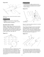
...make it will be needed when reattaching a blade to the saw arbor. If the outside arbor flange, for it possible for most work although an occasional job may require 1-inch facing. Also, an accessory molding cutterhead table insert (F) (not included) must be used with the molding cutterhead...27=2 Figure 26-5, shows a typical dado operation using the molding cutterhead to add a wood facing (G) to produce almost any kind of the standard table insert. Do not lose the outside arbor flange (D) cannot be used in which would prevent the cutter from seating properly. Figure 27=3 G A C...
...make it will be needed when reattaching a blade to the saw arbor. If the outside arbor flange, for it possible for most work although an occasional job may require 1-inch facing. Also, an accessory molding cutterhead table insert (F) (not included) must be used with the molding cutterhead...27=2 Figure 26-5, shows a typical dado operation using the molding cutterhead to add a wood facing (G) to produce almost any kind of the standard table insert. Do not lose the outside arbor flange (D) cannot be used in which would prevent the cutter from seating properly. Figure 27=3 G A C...

Owners Manual
Page 41
...table saw may create a HAZARD or cause product damage. Repair service is available at your nearest Sears Service Center. KICKBACK FINGER T:1.6ram) SET SCREW 1/4-28 x 3/8", NYLOCK TABLE INSERT- STANDARD TABLE INSERT RETAINING BOLT TABLE HEX SOCKET SET SCREW M8 x 20ram ALIGN-A-CUT INSERT... service technician does repairs. 10-IN.TABLESAW MODEL NO.152.221240 When servicing, use only CRAFTSMAN replacement parts. Always order by...OR91077 116 OR91074 117 OR91118 118 OR91078 Description OWNER'S MANUAL - #22124 10" TaNe Saw BLADE GUARD ASSEMBLY, (NOT SHOWN) CONSISTS OF REF #: 1,2, 3, 3a,...
...table saw may create a HAZARD or cause product damage. Repair service is available at your nearest Sears Service Center. KICKBACK FINGER T:1.6ram) SET SCREW 1/4-28 x 3/8", NYLOCK TABLE INSERT- STANDARD TABLE INSERT RETAINING BOLT TABLE HEX SOCKET SET SCREW M8 x 20ram ALIGN-A-CUT INSERT... service technician does repairs. 10-IN.TABLESAW MODEL NO.152.221240 When servicing, use only CRAFTSMAN replacement parts. Always order by...OR91077 116 OR91074 117 OR91118 118 OR91078 Description OWNER'S MANUAL - #22124 10" TaNe Saw BLADE GUARD ASSEMBLY, (NOT SHOWN) CONSISTS OF REF #: 1,2, 3, 3a,...

Owners Manual
Page 42
... 1/4-28 x 3/8" CABINET ASSEMBLY SPEC TAG (C SAW) BEVEL SCALE BLADE ELEVATION AND TILT LABEL HINGE ASSEMBLY...10 FLAT WASHER 2 411 OR91603 CURSOR 1 412 OR91652 1/4-20 x 1 3/4" HEX SOCKET HEAD SCREW 1 413 OR91665 3/8-16 x 1-13/16" HEX HEAD SCREW 1 414 OR91606 KNOB 1 415 OR91607 HANDLE ASSEMBLY 1 416 OR91608 FOOT ASSEMBLY 1 417 OR91609 PAD 2 418 OR91610 PAD, WEAR 2 419 OR91656 3/8-16 NYLON INSERT...STD622505 1/4-20 x 1/2" HEX HEAD SCREW 4 445 OR91616 FRONT RAIL 1 446 OR91617 TABLE ASSEMBLY 12" X 27" 1 N/A OR92011 TEMPLATE (not shown) Service Notes: A ...
... 1/4-28 x 3/8" CABINET ASSEMBLY SPEC TAG (C SAW) BEVEL SCALE BLADE ELEVATION AND TILT LABEL HINGE ASSEMBLY...10 FLAT WASHER 2 411 OR91603 CURSOR 1 412 OR91652 1/4-20 x 1 3/4" HEX SOCKET HEAD SCREW 1 413 OR91665 3/8-16 x 1-13/16" HEX HEAD SCREW 1 414 OR91606 KNOB 1 415 OR91607 HANDLE ASSEMBLY 1 416 OR91608 FOOT ASSEMBLY 1 417 OR91609 PAD 2 418 OR91610 PAD, WEAR 2 419 OR91656 3/8-16 NYLON INSERT...STD622505 1/4-20 x 1/2" HEX HEAD SCREW 4 445 OR91616 FRONT RAIL 1 446 OR91617 TABLE ASSEMBLY 12" X 27" 1 N/A OR92011 TEMPLATE (not shown) Service Notes: A ...


