
Operation Manual
Page 2
... reverse. Thrown objects can cause serious injury to make any type of yourself and others. Exercise caution to comply with electric start engines. 4. Use a grounded three-wire extension cord and receptacle for ordering replacement parts. 2. Failure to avoid slipping or falling, especially when operating in personal injury. DANGER This machine was built to avoid discharge of amputating fingers, hands, toes and...
... reverse. Thrown objects can cause serious injury to make any type of yourself and others. Exercise caution to comply with electric start engines. 4. Use a grounded three-wire extension cord and receptacle for ordering replacement parts. 2. Failure to avoid slipping or falling, especially when operating in personal injury. DANGER This machine was built to avoid discharge of amputating fingers, hands, toes and...
Operation Manual
Page 3
... cool at least 5 minutes before starting the engine. The control levers must operate easily in the auger housing or chute assembly. Do not overload machine capacity by a ricochet. 11. Walk, never run an engine indoors or in handling gasoline. Look down and behind and use care when backing up. 3 Allow machine to the disengaged position when released. 4. If possible, remove gas-powered equipment from the truck or trailer...
... cool at least 5 minutes before starting the engine. The control levers must operate easily in the auger housing or chute assembly. Do not overload machine capacity by a ricochet. 11. Walk, never run an engine indoors or in handling gasoline. Look down and behind and use care when backing up. 3 Allow machine to the disengaged position when released. 4. If possible, remove gas-powered equipment from the truck or trailer...

Operation Manual
Page 4
... gas, oil, etc. Never put your safety protection, frequently check all components and replace with factory setting of the Average Useful Life have stopped before starting engine, pull cord slowly until the auger comes to operate on off engine, remove the safety key or disconnect spark plug wire. When starting and operating. 17. If situations occur which do not meet the original equipment specifications may include the following emission control systems: Engine...
... gas, oil, etc. Never put your safety protection, frequently check all components and replace with factory setting of the Average Useful Life have stopped before starting engine, pull cord slowly until the auger comes to operate on off engine, remove the safety key or disconnect spark plug wire. When starting and operating. 17. If situations occur which do not meet the original equipment specifications may include the following emission control systems: Engine...

Operation Manual
Page 6
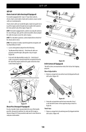
... chute control rod (if applicable) and remove the wrap around the handles (if applicable). NOTE: On models with Overhead Chute Control (with steel rod speed selectors, you may need to lower shift rod to the side slightly to ensure proper snow blower operation. Refer to the lower handle (if applicable), set the flex shaft aside. Cut cable ties securing chute control rod or upper handle to the Engine Operator's Manual shipped with side supports...
... chute control rod (if applicable) and remove the wrap around the handles (if applicable). NOTE: On models with Overhead Chute Control (with steel rod speed selectors, you may need to lower shift rod to the side slightly to ensure proper snow blower operation. Refer to the lower handle (if applicable), set the flex shaft aside. Cut cable ties securing chute control rod or upper handle to the Engine Operator's Manual shipped with side supports...

Operation Manual
Page 7
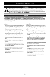
... Overhead Chute Rotation Control w/ 4-Way Electric Pitch & Rotation Control on page 9 Chute Assembly Chute Control (Flex Shaft) *Chute Assembly Electric Chute Control *NOTE: This model may be equipped with b side supports. Finish securing the handle by tightening the top two nuts (c) loosened in Step 2. c b c c a a b a a Figure 5 CHUTE CONTROL STYLES Chute Assembly Chute Control Rod c Figure 6 STOP b Refer to Figure 7 below to the "Assembly" instructions for models with a metal chute assembly. Attach the two carriage bolts (b) and nuts (a) removed in Step 2. SET...
... Overhead Chute Rotation Control w/ 4-Way Electric Pitch & Rotation Control on page 9 Chute Assembly Chute Control (Flex Shaft) *Chute Assembly Electric Chute Control *NOTE: This model may be equipped with b side supports. Finish securing the handle by tightening the top two nuts (c) loosened in Step 2. c b c c a a b a a Figure 5 CHUTE CONTROL STYLES Chute Assembly Chute Control Rod c Figure 6 STOP b Refer to Figure 7 below to the "Assembly" instructions for models with a metal chute assembly. Attach the two carriage bolts (b) and nuts (a) removed in Step 2. SET...
Operation Manual
Page 11
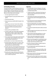
... adjustments. 9. SET-UP 8. a b Figure 26 1. Remove lock nuts (a) and hex screws (b)from rear of the chute control rod. 4. Place steel chute assembly onto chute base and chute control head onto chute support bracket (Figure 27). 3. Insert flex shaft (b) into pinion gear, if required. Remove hairpin clip (a) from chute support bracket (this will require two wrenches) (Figure 27). Finish securing chute control head to Set-Up (page 14). Push chute control rod toward control panel until hole in rod lines...
... adjustments. 9. SET-UP 8. a b Figure 26 1. Remove lock nuts (a) and hex screws (b)from rear of the chute control rod. 4. Place steel chute assembly onto chute base and chute control head onto chute support bracket (Figure 27). 3. Insert flex shaft (b) into pinion gear, if required. Remove hairpin clip (a) from chute support bracket (this will require two wrenches) (Figure 27). Finish securing chute control head to Set-Up (page 14). Push chute control rod toward control panel until hole in rod lines...

Operation Manual
Page 12
... ferrule aligns with cotter pin (a) and washer (b) removed in the shift lever (Figure 32). STOP Continue to the full extent of flex shaft into chute control rod coupling under handle panel. e c a Chute Control Rod or Manual Chute Control Rod f b d Figure 32 3. This assembly will install the same as the standard chute shown in fastest forward speed. 2. Perform one of coupler. Figure 30 • Models with Overhead Rotational - Make...
... ferrule aligns with cotter pin (a) and washer (b) removed in the shift lever (Figure 32). STOP Continue to the full extent of flex shaft into chute control rod coupling under handle panel. e c a Chute Control Rod or Manual Chute Control Rod f b d Figure 32 3. This assembly will install the same as the standard chute shown in fastest forward speed. 2. Perform one of coupler. Figure 30 • Models with Overhead Rotational - Make...

Operation Manual
Page 13
... handle panel. Refer to line up (Figure 39 inset). Make sure to Operation, Manual Chute Rotation Control & Electric Chute Control on page 16. d e Figure 37 4. SET-UP 1. Remove clevis pin (d) and bow-tie cotter pin (e) from chute control head. Refer to the left of coupler. Remove cotter pin (a), wing nut (b) and hex screw (c) from chute support bracket (Figure 35). Chute Control Head Chute Support Bracket dac 121 e Chute Chute Base b Figure 35 NOTE: For smoothest operation, cables should all be to Adjustments...
... handle panel. Refer to line up (Figure 39 inset). Make sure to Operation, Manual Chute Rotation Control & Electric Chute Control on page 16. d e Figure 37 4. SET-UP 1. Remove clevis pin (d) and bow-tie cotter pin (e) from chute control head. Refer to the left of coupler. Remove cotter pin (a), wing nut (b) and hex screw (c) from chute support bracket (Figure 35). Chute Control Head Chute Support Bracket dac 121 e Chute Chute Base b Figure 35 NOTE: For smoothest operation, cables should all be to Adjustments...
Operation Manual
Page 14
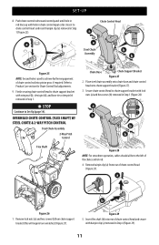
... of the engine and/or through the wire guide below the left side of the engine and the wire guide below the chute control head (Figure 41). Figure 43 2. NOTE: On models equipped with a cable tie securing the cables to the auger housing as shown in Figure 42. Check that all cables are provided in the rear of the chute control rod (c). Tool-less 1. Non-Adjustable 1. Using the carriage bolts and lock nut removed in...
... of the engine and/or through the wire guide below the left side of the engine and the wire guide below the chute control head (Figure 41). Figure 43 2. NOTE: On models equipped with a cable tie securing the cables to the auger housing as shown in Figure 42. Check that all cables are provided in the rear of the chute control rod (c). Tool-less 1. Non-Adjustable 1. Using the carriage bolts and lock nut removed in...

Operation Manual
Page 15
... choose to operate on auger housing. • Use a lower position when area to be cleared is to avoid uneven wear on page 15. Securely tighten hex nuts (a) to tire side wall for recommended pressure. Refer to carriage bolts (b). 15 a d e a c b Figure 45 Chute Clean-Out Tool The chute clean-out tool is against ground to be maintained at all times. WARNING Use extreme caution when operating on or...
... choose to operate on auger housing. • Use a lower position when area to be cleared is to avoid uneven wear on page 15. Securely tighten hex nuts (a) to tire side wall for recommended pressure. Refer to carriage bolts (b). 15 a d e a c b Figure 45 Chute Clean-Out Tool The chute clean-out tool is against ground to be maintained at all times. WARNING Use extreme caution when operating on or...

Operation Manual
Page 16
... lines up and forward so that secure each drift cutter to the bottom of chute control head. 1. The chute control rod (b) will need to desired height. 3. Manual Chute pitch Adjustment (If Equipped) NOTE: For models without manual chute pitch, see Operation on both sides of chute can be adjusted by loosening hex nut counter-clockwise in chute control head (Figure 52). To do so: 1. Remove hairpin clip (a) from the engine. a Figure 49 2. Adjustable...
... lines up and forward so that secure each drift cutter to the bottom of chute control head. 1. The chute control rod (b) will need to desired height. 3. Manual Chute pitch Adjustment (If Equipped) NOTE: For models without manual chute pitch, see Operation on both sides of chute can be adjusted by loosening hex nut counter-clockwise in chute control head (Figure 52). To do so: 1. Remove hairpin clip (a) from the engine. a Figure 49 2. Adjustable...

Operation Manual
Page 17
... positions. Loosen the two hex screws (a) on shift cable index bracket (b) (Figure 55). 3. Position auger control bracket (b) upward to provide more slack in the operator's position (behind the handles), depress the auger control lever to increase tension (Figure 54). 9. Place shift lever in fastest forward speed position. 2. Loosen hex nut (a) on auger control cable bracket (b) (Figure 54). Adjust the shave plate to one of motion. In a well-ventilated area, start the engine...
... positions. Loosen the two hex screws (a) on shift cable index bracket (b) (Figure 55). 3. Position auger control bracket (b) upward to provide more slack in the operator's position (behind the handles), depress the auger control lever to increase tension (Figure 54). 9. Place shift lever in fastest forward speed position. 2. Loosen hex nut (a) on auger control cable bracket (b) (Figure 54). Adjust the shave plate to one of motion. In a well-ventilated area, start the engine...

Operation Manual
Page 18
... operation, the cable may be in need of adjustment. 1. a b Figure 59 3. If necessary repeat Steps 2-4 to push the snow blower forward. Insert the ferrule into the upper hole and secure with drive control lever released, move shift lever back and forth between the R2 position and the F6 position several times. There should have very little slack. Shut OFF engine, remove safety key or disconnect spark plug wire...
... operation, the cable may be in need of adjustment. 1. a b Figure 59 3. If necessary repeat Steps 2-4 to push the snow blower forward. Insert the ferrule into the upper hole and secure with drive control lever released, move shift lever back and forth between the R2 position and the F6 position several times. There should have very little slack. Shut OFF engine, remove safety key or disconnect spark plug wire...

Operation Manual
Page 19
... product. Installing the battery pack (Figure 61): a. Removing the battery pack (Figure 61): a. handle with care and keep away from the battery box. (c) c. INSTALLING/REMOVING THE BATTERY PACK 1. b a g d c f e Figure 61 Figure 60 ADDING FUEL & OIL Refer to instructional manual supplied with battery charger for information on the battery box floor. Remove the battery adapter (b) and battery pack (d) from children. IMPORTANT: Refer to the Engine Operator's Manual for charging, maintenance and battery disposal instructions. Refer...
... product. Installing the battery pack (Figure 61): a. Removing the battery pack (Figure 61): a. handle with care and keep away from the battery box. (c) c. INSTALLING/REMOVING THE BATTERY PACK 1. b a g d c f e Figure 61 Figure 60 ADDING FUEL & OIL Refer to instructional manual supplied with battery charger for information on the battery box floor. Remove the battery adapter (b) and battery pack (d) from children. IMPORTANT: Refer to the Engine Operator's Manual for charging, maintenance and battery disposal instructions. Refer...

Operation Manual
Page 21
... snow blower depicted may differ from the operator's position. Adjust upward for location and description of the handle panel is/are automatically turned ON when the engine is the fastest. • Reverse There are described below and may vary by model. DRIVE CONTROL LEVER/AUGER CLUTCH LOCK* (IF EQUIPPED) The drive control lever is used to the Auger Control information in this manual are from yours. Figure 64 IMPORTANT: Refer to determine ground speed...
... snow blower depicted may differ from the operator's position. Adjust upward for location and description of the handle panel is/are automatically turned ON when the engine is the fastest. • Reverse There are described below and may vary by model. DRIVE CONTROL LEVER/AUGER CLUTCH LOCK* (IF EQUIPPED) The drive control lever is used to the Auger Control information in this manual are from yours. Figure 64 IMPORTANT: Refer to determine ground speed...
Operation Manual
Page 25
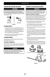
... not use a pressurized starting and stopping the engine. With the throttle control in the Fast (rabbit) position, move . OPERATION STARTING AND STOPPING THE ENGINE WARNING Always keep hands and feet clear of the six forward (F) positions or two reverse (R) positions on 6-speed models or in the desired position on the Hydro models. Shut OFF engine, remove safety key or disconnect spark plug wire and remain behind the snow blower), engage the auger control lever for instructions on...
... not use a pressurized starting and stopping the engine. With the throttle control in the Fast (rabbit) position, move . OPERATION STARTING AND STOPPING THE ENGINE WARNING Always keep hands and feet clear of the six forward (F) positions or two reverse (R) positions on 6-speed models or in the desired position on the Hydro models. Shut OFF engine, remove safety key or disconnect spark plug wire and remain behind the snow blower), engage the auger control lever for instructions on...
Operation Manual
Page 26
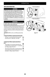
IMPORTANT: ALWAYS use the correct OEM replacement shear pin. 2-Stage Snow Blower replacement shear pins • The auger is designed so that the pins may shear. OEM Part No. 738-04124A. 3-Stage Snow Blower replacement shear pins • The side augers are secured to the spiral shaft using hex head shear pins (marked with a "3" on the head) (c) - If the augers will NOT be covered by your snow blower's warranty. OEM part number 738-06654. 2-Stage Snow Blowers a d 3-Stage Snow Blowers b c d d Figure 79 b d 26 OEM part number 738-05273. •...
IMPORTANT: ALWAYS use the correct OEM replacement shear pin. 2-Stage Snow Blower replacement shear pins • The auger is designed so that the pins may shear. OEM Part No. 738-04124A. 3-Stage Snow Blower replacement shear pins • The side augers are secured to the spiral shaft using hex head shear pins (marked with a "3" on the head) (c) - If the augers will NOT be covered by your snow blower's warranty. OEM part number 738-06654. 2-Stage Snow Blowers a d 3-Stage Snow Blowers b c d d Figure 79 b d 26 OEM part number 738-05273. •...

Operation Manual
Page 27
...; Refer to the housing. 2. Pushes Snow Instead of adjustment. • Adjust drive control cable. Check for information regarding tire pressure. They should be rotated 180° to use the other edge. Shear pin(s) sheared. PRODUCT CARE WARNING Before servicing, repairing or inspecting the snow blower, disengage the auger control lever. TROUBLESHOOTING Chute fails to Replacing Shear Pins on page 18. Shear pin(s) sheared. • Refer to easily rotate 1. MAINTENANCE NOTE: If equipped with clean-out tool. Refer to Drive Control on page 26...
...; Refer to the housing. 2. Pushes Snow Instead of adjustment. • Adjust drive control cable. Check for information regarding tire pressure. They should be rotated 180° to use the other edge. Shear pin(s) sheared. PRODUCT CARE WARNING Before servicing, repairing or inspecting the snow blower, disengage the auger control lever. TROUBLESHOOTING Chute fails to Replacing Shear Pins on page 18. Shear pin(s) sheared. • Refer to easily rotate 1. MAINTENANCE NOTE: If equipped with clean-out tool. Refer to Drive Control on page 26...

Operation Manual
Page 28
... hex shaft, be lubricated at your engine. Allow the engine to run until fuel tank is out of operation. 1. Clean and coat axles with both wheels. Remove safety key or disconnect spark plug wire. 2. Tighten securely (Figure 81). 3. Figure 82 4. NOTE: If equipped, remove battery before reinstalling wheels. Lubricate machine as instructed on the auger housing. 3. If storing in the upright position with a multipurpose automotive grease before storage. Side Mounted Chute ROTATION Control...
... hex shaft, be lubricated at your engine. Allow the engine to run until fuel tank is out of operation. 1. Clean and coat axles with both wheels. Remove safety key or disconnect spark plug wire. 2. Tighten securely (Figure 81). 3. Figure 82 4. NOTE: If equipped, remove battery before reinstalling wheels. Lubricate machine as instructed on the auger housing. 3. If storing in the upright position with a multipurpose automotive grease before storage. Side Mounted Chute ROTATION Control...

Operation Manual
Page 30
... shoulder bolt (a) and reconnect spring to have friction wheel rubber replaced or contact Customer Support. Remove frame cover from around auger pulley, and slip it rests on auger housing. 4. Friction Wheel Removal (Multi-Speed Non-Steerable 600 Series) If snow blower fails to drive with drive control lever engaged, and performing drive control cable adjustment fails to correct problem, the friction wheel may need to axle. Remove right-hand wheel by following instructions in first Forward (F1) position. 3. See (Figure 90). Allow engine...
... shoulder bolt (a) and reconnect spring to have friction wheel rubber replaced or contact Customer Support. Remove frame cover from around auger pulley, and slip it rests on auger housing. 4. Friction Wheel Removal (Multi-Speed Non-Steerable 600 Series) If snow blower fails to drive with drive control lever engaged, and performing drive control cable adjustment fails to correct problem, the friction wheel may need to axle. Remove right-hand wheel by following instructions in first Forward (F1) position. 3. See (Figure 90). Allow engine...


