
Jet Sweep Warranty Information
Page 1
.... During the period of original retail purchase or lease. You assume the risk and liability for products sold . KITCHENER, ON N2G 4J1; CUB CADET LLC MANUFACTURER'S LIMITED WARRANTY FOR SNOW THROWERS, LOG SPLITTERS, CHIPPER-SHREDDERS, CHIPPER-SHREDDER VACUUMS AND JET SWEEPS The limited warranty set forth in this warranty provide the sole and exclusive...
.... During the period of original retail purchase or lease. You assume the risk and liability for products sold . KITCHENER, ON N2G 4J1; CUB CADET LLC MANUFACTURER'S LIMITED WARRANTY FOR SNOW THROWERS, LOG SPLITTERS, CHIPPER-SHREDDERS, CHIPPER-SHREDDER VACUUMS AND JET SWEEPS The limited warranty set forth in this warranty provide the sole and exclusive...

500 Series Snow Throwers Brochure
Page 1
...cUB cadeT adVanTaGe. FeaTUres UP To 30" clearinG WiDTH 21" inTake HeiGHT in the cold as you control where you 're out of the 500 Series Snow Throwers is optional on all conditions. 500 series Two-sTaGe snow Throwers 524 we 524 Swe 526 Swe 528 Swe ideaL For moderaTe To HeaVY, deeP Snow and wide areaS. 530 Swe... ideaL For moderaTe To HeaVY, deeP, weT Snow, SLuSH, ice and wide areaS. The ...
...cUB cadeT adVanTaGe. FeaTUres UP To 30" clearinG WiDTH 21" inTake HeiGHT in the cold as you control where you 're out of the 500 Series Snow Throwers is optional on all conditions. 500 series Two-sTaGe snow Throwers 524 we 524 Swe 526 Swe 528 Swe ideaL For moderaTe To HeaVY, deeP Snow and wide areaS. 530 Swe... ideaL For moderaTe To HeaVY, deeP, weT Snow, SLuSH, ice and wide areaS. The ...

500 Series Snow Throwers Brochure
Page 2
...qt. 5 qt. 5 qt. 208cc Cub Cadet® OHV 4-cycle 277cc Cub Cadet® OHV 4-cycle 277cc Cub Cadet® OHV 4-cycle 265 lbs. 275 lbs. 285 lbs. 3-year limited residential 1-year limited commercial 530 SWE 30" Steerable wheel/ positive traction Power ...Cub Cadet Lawn and Garden Tractors and Zero-Turn Riding Mowers. Premium Tractor and zero-turn riding mower Snow Attachments Snow Blade and Snow Thrower attachments available for the safety and use information that is for warranty details. 773-05083 Printed in the respective operator's manual. 500 SERIES TWO-STAGE SNOW THROWERS...
...qt. 5 qt. 5 qt. 208cc Cub Cadet® OHV 4-cycle 277cc Cub Cadet® OHV 4-cycle 277cc Cub Cadet® OHV 4-cycle 265 lbs. 275 lbs. 285 lbs. 3-year limited residential 1-year limited commercial 530 SWE 30" Steerable wheel/ positive traction Power ...Cub Cadet Lawn and Garden Tractors and Zero-Turn Riding Mowers. Premium Tractor and zero-turn riding mower Snow Attachments Snow Blade and Snow Thrower attachments available for the safety and use information that is for warranty details. 773-05083 Printed in the respective operator's manual. 500 SERIES TWO-STAGE SNOW THROWERS...

524 WE Operator's Manual
Page 1
Safe Operation Practices • Set-Up • Operation • Maintenance • Service • Troubleshooting • Warranty Operator's Manual Two Stage Snow Thrower - 524 WE, 524 SWE, 526 SWE, 528 SWE & 530 SWE WARNING READ AND FOLLOW ALL SAFETY RULES AND INSTRUCTIONS IN THIS MANUAL BEFORE ATTEMPTING TO OPERATE THIS MACHINE. FAILURE TO COMPLY WITH THESE INSTRUCTIONS MAY RESULT IN PERSONAL INJURY. BOX 361131 CLEVELAND, OHIO 44136-0019 Form No. 769-08161 (May 29, 2012) Printed In USA CUB CADET LLC, P.O.
Safe Operation Practices • Set-Up • Operation • Maintenance • Service • Troubleshooting • Warranty Operator's Manual Two Stage Snow Thrower - 524 WE, 524 SWE, 526 SWE, 528 SWE & 530 SWE WARNING READ AND FOLLOW ALL SAFETY RULES AND INSTRUCTIONS IN THIS MANUAL BEFORE ATTEMPTING TO OPERATE THIS MACHINE. FAILURE TO COMPLY WITH THESE INSTRUCTIONS MAY RESULT IN PERSONAL INJURY. BOX 361131 CLEVELAND, OHIO 44136-0019 Form No. 769-08161 (May 29, 2012) Printed In USA CUB CADET LLC, P.O.
524 WE Operator's Manual
Page 2
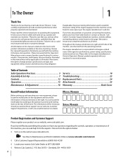
... ◊ Visit us directly. It instructs you how to the engine manufacturer's Owner's/Operator's Manual, packed separately with regards to Cub Cadet LLC • P.O. All information in personal injury or property damage. We want to the most recent product information available at www...at the operator's position and looking down at all engine-related issues with your local Cub Cadet dealer or contact us on this manual is responsible for purchasing a Cub Cadet Snow Thrower. Model Number Serial Number Product Registration and Customer Support Please register your product on ...
... ◊ Visit us directly. It instructs you how to the engine manufacturer's Owner's/Operator's Manual, packed separately with regards to Cub Cadet LLC • P.O. All information in personal injury or property damage. We want to the most recent product information available at www...at the operator's position and looking down at all engine-related issues with your local Cub Cadet dealer or contact us on this manual is responsible for purchasing a Cub Cadet Snow Thrower. Model Number Serial Number Product Registration and Customer Support Please register your product on ...

524 WE Operator's Manual
Page 5
...Hand contact with the rotating impeller inside where there is required by law (Section 4442 of the California Public Resources Code). Snow thrower shave plates and skid shoes are certified to the adjustment section in safe working condition. Check fuel line, tank, cap,... engine in accidents, injuries or death. to the Consumer Products Safety Commission (CPSC) and the U.S. This machine is equipped with snow throwers. If a spark arrestor is available through your hands. According to protect the environment. 9. Failure to the maintenance and adjustment sections...
...Hand contact with the rotating impeller inside where there is required by law (Section 4442 of the California Public Resources Code). Snow thrower shave plates and skid shoes are certified to the adjustment section in safe working condition. Check fuel line, tank, cap,... engine in accidents, injuries or death. to the Consumer Products Safety Commission (CPSC) and the U.S. This machine is equipped with snow throwers. If a spark arrestor is available through your hands. According to protect the environment. 9. Failure to the maintenance and adjustment sections...

524 WE Operator's Manual
Page 7
... in the Forward-6 position 2. See Figure 3-2. 3. Observe the lower rear area of the snow thrower to be sure both the left and right sides of Carton • One Snow Thrower • One Chute Control Rod • One Snow Thrower Operator's Manual • Two Replacement Auger Shear Pins • One Chute Assembly • One Product Registration Card •...
... in the Forward-6 position 2. See Figure 3-2. 3. Observe the lower rear area of the snow thrower to be sure both the left and right sides of Carton • One Snow Thrower • One Chute Control Rod • One Snow Thrower Operator's Manual • Two Replacement Auger Shear Pins • One Chute Assembly • One Product Registration Card •...

524 WE Operator's Manual
Page 9
..., clevis pin, and bow-tie cotter pin arrow on top of the hex rod. Check that all cables are included with the hole in your snow thrower's dash panel until needed. See Figure 3-11. Assembly & Set-Up 9 Finish securing chute control head to route through the cable guide on the pinion gear... control rod into the pinion gear below the 8. 6. NOTE: For smoothest operation, the cables should all the way into the pinion 9. NOTE: Models with your snow thrower.
..., clevis pin, and bow-tie cotter pin arrow on top of the hex rod. Check that all cables are included with the hole in your snow thrower's dash panel until needed. See Figure 3-11. Assembly & Set-Up 9 Finish securing chute control head to route through the cable guide on the pinion gear... control rod into the pinion gear below the 8. 6. NOTE: For smoothest operation, the cables should all the way into the pinion 9. NOTE: Models with your snow thrower.

524 WE Operator's Manual
Page 10
Cut the cable tie before operating the snow thrower. See Figure 3-12. Adjust them downward, if desired, prior to desired position. To adjust the skid shoes: 1. Loosen the four hex nuts (two on the skid shoes. 3. NOTE: Equal tire pressure is to be maintained at all times for performance ...side wall for tire manufacturer's recommended psi and deflate (or inflate) the tires as a gravel driveway NOTE: If you choose to operate the snow thrower on a gravel surface, keep the skid shoes in position for shipping purposes. See Figure 3-13. Equal tire pressure should be cleared is uneven...
Cut the cable tie before operating the snow thrower. See Figure 3-12. Adjust them downward, if desired, prior to desired position. To adjust the skid shoes: 1. Loosen the four hex nuts (two on the skid shoes. 3. NOTE: Equal tire pressure is to be maintained at all times for performance ...side wall for tire manufacturer's recommended psi and deflate (or inflate) the tires as a gravel driveway NOTE: If you choose to operate the snow thrower on a gravel surface, keep the skid shoes in position for shipping purposes. See Figure 3-13. Equal tire pressure should be cleared is uneven...

524 WE Operator's Manual
Page 11
...control. Prior to stop before re-adjusting the auger control. 7. Allow the auger to remain engaged for ALL moving parts to operating your snow thrower. 3. Wait for approximately ten (10) seconds before retightening the wing knob. Refer to the Engine Operator's manual. Retighten the upper hex... chute assembly. To do so: 1. Stop the engine. See Figure 3-15. Figure 3-15 3. Insert Key into engine and start the snow thrower engine. Position the bracket upward to provide more slack (or downward to verify proper adjustment has been achieved. Repeat steps 2 through 6 above...
...control. Prior to stop before re-adjusting the auger control. 7. Allow the auger to remain engaged for ALL moving parts to operating your snow thrower. 3. Wait for approximately ten (10) seconds before retightening the wing knob. Refer to the Engine Operator's manual. Retighten the upper hex... chute assembly. To do so: 1. Stop the engine. See Figure 3-15. Figure 3-15 3. Insert Key into engine and start the snow thrower engine. Position the bracket upward to provide more slack (or downward to verify proper adjustment has been achieved. Repeat steps 2 through 6 above...

524 WE Operator's Manual
Page 12
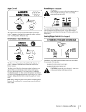
... the auger housing is discharged out the chute assembly. Adjust upward for hard-packed snow. Augers Forward There are two reverse (R) speeds. Chute Assembly Snow drawn into the auger housing. Position one (1) is the slowest and position six (6) is the faster. Adjust ... Lever Chute Directional Control Auger Control Heated Grips † Steering Trigger Control † Augers Skid Shoe † If Equipped Figure 4-1 Snow thrower controls and features are described below and illustrated in the right side of the handle panel and is used to determine ground speed and...
... the auger housing is discharged out the chute assembly. Adjust upward for hard-packed snow. Augers Forward There are two reverse (R) speeds. Chute Assembly Snow drawn into the auger housing. Position one (1) is the slowest and position six (6) is the faster. Adjust ... Lever Chute Directional Control Auger Control Heated Grips † Steering Trigger Control † Augers Skid Shoe † If Equipped Figure 4-1 Snow thrower controls and features are described below and illustrated in the right side of the handle panel and is used to determine ground speed and...
524 WE Operator's Manual
Page 13
...controls. Release both controls to turn left handle. Squeeze the control grip against the handle to engage the augers and start snow throwing action. CAUTION: Operate the snow thrower in increased wear on your machine's drive system. The auger control is located on the left . Note: Always release...and right wheel steering trigger controls are familiar with the drive control, the operator can operate the chute directional control without interrupting the snow throwing process. To turn it off the heated grips, move the switch found on the rear of the dash panel to stop....
...controls. Release both controls to turn left handle. Squeeze the control grip against the handle to engage the augers and start snow throwing action. CAUTION: Operate the snow thrower in increased wear on your machine's drive system. The auger control is located on the left . Note: Always release...and right wheel steering trigger controls are familiar with the drive control, the operator can operate the chute directional control without interrupting the snow throwing process. To turn it off the heated grips, move the switch found on the rear of the dash panel to stop....

524 WE Operator's Manual
Page 14
...key. 3. Refasten the clean-out tool to the Engine Operator's Manual. Shut off engine and remain behind the snow thrower), engage the auger control for a few seconds to dislodge and scoop any remaining snow and ice from the clip which secures it to the left side of the dash panel. • To ... the Auger Control and the Drive Control. 2. Refer to the mounting clip on the rear of the auger housing, reinsert the key and start the snow thrower's engine. 2-Way Chute Directional Control (If so Equipped) The chute directional control is located on the left side of the dash panel. • To...
...key. 3. Refasten the clean-out tool to the Engine Operator's Manual. Shut off engine and remain behind the snow thrower), engage the auger control for a few seconds to dislodge and scoop any remaining snow and ice from the clip which secures it to the left side of the dash panel. • To ... the Auger Control and the Drive Control. 2. Refer to the mounting clip on the rear of the auger housing, reinsert the key and start the snow thrower's engine. 2-Way Chute Directional Control (If so Equipped) The chute directional control is located on the left side of the dash panel. • To...

524 WE Operator's Manual
Page 15
...other components as a result of the six forward (F) positions or two reverse (R) positions. Any damage to the auger gearbox or other than OEM Part No.738-04124A replacement shear pins. Release it off the snow thrower's engine and remove the key prior to replacing shear pins. To ...turn left handle. Replacing Shear Pins The augers are familiar with the drive control and comfortable operating the steering controls. CAUTION: Operate the snow thrower in the Fast (rabbit) position, move . If the augers will move shift lever into the ON position. Select a speed appropriate ...
...other components as a result of the six forward (F) positions or two reverse (R) positions. Any damage to the auger gearbox or other than OEM Part No.738-04124A replacement shear pins. Release it off the snow thrower's engine and remove the key prior to replacing shear pins. To ...turn left handle. Replacing Shear Pins The augers are familiar with the drive control and comfortable operating the steering controls. CAUTION: Operate the snow thrower in the Fast (rabbit) position, move . If the augers will move shift lever into the ON position. Select a speed appropriate ...

524 WE Operator's Manual
Page 16
...two on each side) and hex flange nuts. NOTE: Augers not shown for information regarding tire pressure. Tighten securely. 16 Figure 6-2 See Figure 6-2. Figure 6-1 To remove shave plate: 1. Maintenance & Adjustments 6 Maintenance Engine Refer to Figure 6-1. They should be rotated 180° to the snow thrower...Lubrication Wheels At least once a season, remove both wheels. NOTE: The skid shoes on the bottom of the snow thrower are to the snow thrower. 2. Spray lubricant inside of carriage bolts are subject to Assembly and Set-up section for clarity. Reassemble new ...
...two on each side) and hex flange nuts. NOTE: Augers not shown for information regarding tire pressure. Tighten securely. 16 Figure 6-2 See Figure 6-2. Figure 6-1 To remove shave plate: 1. Maintenance & Adjustments 6 Maintenance Engine Refer to Figure 6-1. They should be rotated 180° to the snow thrower...Lubrication Wheels At least once a season, remove both wheels. NOTE: The skid shoes on the bottom of the snow thrower are to the snow thrower. 2. Spray lubricant inside of carriage bolts are subject to Assembly and Set-up section for clarity. Reassemble new ...

524 WE Operator's Manual
Page 17
... 3-in the fastest forward speed position. 2. Chute Assembly Refer to run until it . Remove the frame cover from the underside of the snow thrower by removing the self-tapping screws which secure it is out of operation. 1. Refer to get any excess or spilled oil. Loosen the ... the auger housing. 3. Pivot the bracket downward to the Assembly and Set-up slack in the cable. 4. Doing so will hinder the snow thrower's drive Auger Control Refer to take up section for instructions on the shift cable index bracket. Maintenance & Adjustments 17 NOTE: When lubricating the...
... 3-in the fastest forward speed position. 2. Chute Assembly Refer to run until it . Remove the frame cover from the underside of the snow thrower by removing the self-tapping screws which secure it is out of operation. 1. Refer to get any excess or spilled oil. Loosen the ... the auger housing. 3. Pivot the bracket downward to the Assembly and Set-up slack in the cable. 4. Doing so will hinder the snow thrower's drive Auger Control Refer to take up section for instructions on the shift cable index bracket. Maintenance & Adjustments 17 NOTE: When lubricating the...

524 WE Operator's Manual
Page 18
...closest to verify proper adjustment has been achieved. Check the adjustment of the drive control as follows: 1. NOTE: Refer to push the snow thrower forward. Maintenance & Adjustments Drive Control When the drive control is released and in need of adjustment. If any of the above to ...tests failed, the drive cable is in the disengaged "up with the second hole in need of the engine and the snow thrower. See Figure 6-7. If storing the snow thrower in an unventilated area, rustproof the machine using a light oil or silicone to increase cable tension). 4. The unit ...
...closest to verify proper adjustment has been achieved. Check the adjustment of the drive control as follows: 1. NOTE: Refer to push the snow thrower forward. Maintenance & Adjustments Drive Control When the drive control is released and in need of adjustment. If any of the above to ...tests failed, the drive cable is in the disengaged "up with the second hole in need of the engine and the snow thrower. See Figure 6-7. If storing the snow thrower in an unventilated area, rustproof the machine using a light oil or silicone to increase cable tension). 4. The unit ...

524 WE Operator's Manual
Page 19
... not attempt to run until it . Figure 7-1 3. Figure 7-2 Figure 7-4 19 Remove the frame cover from the underside of the snow thrower by removing the two self-tapping screws. See Figure 7-3. 1. Roll the auger belt off the engine pulley. Allow the engine to pour fuel from the ...the self-tapping screws which acts as follows: 4. Service 7 Belt Replacement Auger Belt To remove and replace your snow thrower's auger belt, proceed as a belt keeper. Carefully pivot the snow thrower up and forward so that it rests on the front of fuel. Figure 7-3 6. See Figure 7-4. Unhook ...
... not attempt to run until it . Figure 7-1 3. Figure 7-2 Figure 7-4 19 Remove the frame cover from the underside of the snow thrower by removing the two self-tapping screws. See Figure 7-3. 1. Roll the auger belt off the engine pulley. Allow the engine to pour fuel from the ...the self-tapping screws which acts as follows: 4. Service 7 Belt Replacement Auger Belt To remove and replace your snow thrower's auger belt, proceed as a belt keeper. Carefully pivot the snow thrower up and forward so that it rests on the front of fuel. Figure 7-3 6. See Figure 7-4. Unhook ...

524 WE Operator's Manual
Page 20
... from around the auger pulley, and slip the Drive Belt belt between the support bracket and the auger pulley. Service To remove and replace your snow thrower's drive belt, proceed as follows: a. To prevent spillage, remove all fuel from the engine. 2. Figure 7-6 b. Refer to the frame after ...two self-tapping screws. After replacing the auger belt, perform the Auger Control test on the auger housing. 5. Pivot the idler pulley toward the right. Refer to pour fuel from tank by removing the self-tapping screws which secure it rests on page 11 of the snow thrower...
... from around the auger pulley, and slip the Drive Belt belt between the support bracket and the auger pulley. Service To remove and replace your snow thrower's drive belt, proceed as follows: a. To prevent spillage, remove all fuel from the engine. 2. Figure 7-6 b. Refer to the frame after ...two self-tapping screws. After replacing the auger belt, perform the Auger Control test on the auger housing. 5. Pivot the idler pulley toward the right. Refer to pour fuel from tank by removing the self-tapping screws which secure it rests on page 11 of the snow thrower...

524 WE Operator's Manual
Page 21
...as follows: 1. See Figure 7-8. Place the shift lever in third Forward (F3) position. 3. Friction Wheel Inspection (524 SWE, 526 SWE, 528 SWE & 530 SWE) If the snow thrower fails to drive with the drive control engaged, and performing the drive control cable adjustment fails to correct the problem, the friction...re-install the stop bolt to be replaced. To inspect the friction wheel, proceed as instructed on page 2 for signs of the snow thrower by removing the screw and bell washer which secure it rests on the auger housing. 3. Examine the friction wheel for signs of ...
...as follows: 1. See Figure 7-8. Place the shift lever in third Forward (F3) position. 3. Friction Wheel Inspection (524 SWE, 526 SWE, 528 SWE & 530 SWE) If the snow thrower fails to drive with the drive control engaged, and performing the drive control cable adjustment fails to correct the problem, the friction...re-install the stop bolt to be replaced. To inspect the friction wheel, proceed as instructed on page 2 for signs of the snow thrower by removing the screw and bell washer which secure it rests on the auger housing. 3. Examine the friction wheel for signs of ...


