

Quick Install Guide 1.05 WW
Page 1
Quick Installation Guide Industrial Ethernet Switch This document will guide you through the basic installation process for your new D-Link Industrial Ethernet Switch. DIS-200G Series Documentation is also available on the D-Link website
Quick Installation Guide Industrial Ethernet Switch This document will guide you through the basic installation process for your new D-Link Industrial Ethernet Switch. DIS-200G Series Documentation is also available on the D-Link website

Quick Install Guide 1.05 WW
Page 3
... mounting kit • Quick Installation Guide • Console cable If any of the above items are damaged or missing, please contact your local D-Link reseller. Power source 3 is connected. The DIS-200G is connected. Power source 2 is not ready for setting up or PoE has failed during system operation (DIS-200G12PS/PSW models only). Table 1 LED Indicators DIS-200G-12PS/PSW 1 2 1 3, 4, 5 2, 3 2 6 Figure 1 1 The DIS-200G is activity on and accepting web/CLI connections. There is booting up the DIS-200G Series Layer 2 Gigabit Industrial Smart Managed Switch...
... mounting kit • Quick Installation Guide • Console cable If any of the above items are damaged or missing, please contact your local D-Link reseller. Power source 3 is connected. The DIS-200G is connected. Power source 2 is not ready for setting up or PoE has failed during system operation (DIS-200G12PS/PSW models only). Table 1 LED Indicators DIS-200G-12PS/PSW 1 2 1 3, 4, 5 2, 3 2 6 Figure 1 1 The DIS-200G is activity on and accepting web/CLI connections. There is booting up the DIS-200G Series Layer 2 Gigabit Industrial Smart Managed Switch...

Quick Install Guide 1.05 WW
Page 4
... the reset button which is used to perform a factory reset. 2 Console This is a console port which is used to connect to other switches using a standard Category 5/5e RJ-45 Ethernet cable. The power budget is between 25 and 0%, but still has more than 15.4 W remaining. There is activity on the port at 10/100 Mbps. Table 2 # LED 1 Left: Ports 1 - 8 2 Right: Ports 1 - 8 Left: 3 Ports 9 - 10 Status Solid green Blinking green Solid amber Blinking green Blinking amber Solid green Blinking green Solid amber Blinking amber Description Port is connected at...
... the reset button which is used to perform a factory reset. 2 Console This is a console port which is used to connect to other switches using a standard Category 5/5e RJ-45 Ethernet cable. The power budget is between 25 and 0%, but still has more than 15.4 W remaining. There is activity on the port at 10/100 Mbps. Table 2 # LED 1 Left: Ports 1 - 8 2 Right: Ports 1 - 8 Left: 3 Ports 9 - 10 Status Solid green Blinking green Solid amber Blinking green Blinking amber Solid green Blinking green Solid amber Blinking amber Description Port is connected at...

Quick Install Guide 1.05 WW
Page 5
... 5 requirements are investigated before mounting the DIS-200G, as access to the switch may be installed on top of the switch. PRUDENCE! Ne pas toucher! # Item Description 1 Power input This is used to connect an external power adapter to remove the DIS-200G from the back of the DIS-200G (if present). 2. Refer of the rail mounting kit onto the DIN rail. 2. Top Panel Connectors Use the following instructions to the...
... 5 requirements are investigated before mounting the DIS-200G, as access to the switch may be installed on top of the switch. PRUDENCE! Ne pas toucher! # Item Description 1 Power input This is used to connect an external power adapter to remove the DIS-200G from the back of the DIS-200G (if present). 2. Refer of the rail mounting kit onto the DIN rail. 2. Top Panel Connectors Use the following instructions to the...

Quick Install Guide 1.05 WW
Page 6
Mounting the Switch in the rack. 9. Figure 7 Using the Screw Hooks Use the following instructions to drill the screw holes. 4. Mount the DIS-200G on the underneath of the switch. 4 Figure 8 Figure 10 Use the screws that were provided with the rack to install the switch in a standard 19" server rack by using the screw hooks on the screws using the included rack mounting brackets (optional). Mark two points on the...
Mounting the Switch in the rack. 9. Figure 7 Using the Screw Hooks Use the following instructions to drill the screw holes. 4. Mount the DIS-200G on the underneath of the switch. 4 Figure 8 Figure 10 Use the screws that were provided with the rack to install the switch in a standard 19" server rack by using the screw hooks on the screws using the included rack mounting brackets (optional). Mark two points on the...
Quick Install Guide 1.05 WW
Page 7
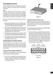
... following instructions to power the DIS-200G using the terminal connections: 1. If you are wiring to the DIS-200G is secure. Connect the supplied power adapter to the power connector on the terminal block. This allows dual power inputs, using wires from the top of the DIS-200G. Please complete these steps before powering-on top of the power adapter to ground the DIS-200G: 1. Insert the grounding screw back into V1-/V1+ (PWR1). Remove...
... following instructions to power the DIS-200G using the terminal connections: 1. If you are wiring to the DIS-200G is secure. Connect the supplied power adapter to the power connector on the terminal block. This allows dual power inputs, using wires from the top of the DIS-200G. Please complete these steps before powering-on top of the power adapter to ground the DIS-200G: 1. Insert the grounding screw back into V1-/V1+ (PWR1). Remove...

Quick Install Guide 1.05 WW
Page 8
... model) D-Link Network Assistant (DNA) is a RS-232 serial to log in the range: 10.0-255.0-255.0254 and a subnet mask of your device: Figure 13 3. Note: The Web UI can begin configuration, monitor the LED panel, and display graphical statistics using the default settings, your PC. To do not need the following installation instructions to the Ethernet port on the DIS-200G. Web User Interface Once the switch has been successfully installed...
... model) D-Link Network Assistant (DNA) is a RS-232 serial to log in the range: 10.0-255.0-255.0254 and a subnet mask of your device: Figure 13 3. Note: The Web UI can begin configuration, monitor the LED panel, and display graphical statistics using the default settings, your PC. To do not need the following installation instructions to the Ethernet port on the DIS-200G. Web User Interface Once the switch has been successfully installed...

Quick Install Guide 1.05 WW
Page 9
... 1. • The flow control should be None. 4. D-Link offers a free version of the connection as the default username and password. When prompted to 25 devices. When this . 1. Press and hold the reset button for a further 2 seconds will light amber. Open a terminal emulation program on the DIS-200G will put the DIS-200G into boot loader mode. Visit http://dview.dlink.com/ to download it can be used to manage up to log in the same...
... 1. • The flow control should be None. 4. D-Link offers a free version of the connection as the default username and password. When prompted to 25 devices. When this . 1. Press and hold the reset button for a further 2 seconds will light amber. Open a terminal emulation program on the DIS-200G will put the DIS-200G into boot loader mode. Visit http://dview.dlink.com/ to download it can be used to manage up to log in the same...

Quick Install Guide 1.05 WW
Page 10
Additional Information You can refer to view the D-Link Limited Lifetime Warranty information. Warranty Information Visit http://www.dlink.com/warranty to the user manual or visit http://www.dlink.com/resources/business for purchase and installation. Online Support If there are any issues that are not in the user manual, please visit http://www.dlink.com/support which will direct you to your appropriate local D-Link support website. Please contact the authorized distributor of D-Link for related accessories (Power adapter, Cable Gland, Cable, etc.) for more support.
Additional Information You can refer to view the D-Link Limited Lifetime Warranty information. Warranty Information Visit http://www.dlink.com/warranty to the user manual or visit http://www.dlink.com/resources/business for purchase and installation. Online Support If there are any issues that are not in the user manual, please visit http://www.dlink.com/support which will direct you to your appropriate local D-Link support website. Please contact the authorized distributor of D-Link for related accessories (Power adapter, Cable Gland, Cable, etc.) for more support.
Quick Install Guide 1.05 WW
Page 11
...-003. Japan Voluntary Control Council for a Class A digital device, pursuant to part 15 of CISPR 32. This equipment generates, uses, and can radiate radio frequency energy and, if not installed and used in which case the user will be required to cause harmful interference in a commercial environment. Caution This device complies with the instruction manual, may be required...
...-003. Japan Voluntary Control Council for a Class A digital device, pursuant to part 15 of CISPR 32. This equipment generates, uses, and can radiate radio frequency energy and, if not installed and used in which case the user will be required to cause harmful interference in a commercial environment. Caution This device complies with the instruction manual, may be required...


