
Product Manual
Page 1
DKVM-2/4 2/4-Port Keyboard, Video, and Mouse Switch Manual Rev. 1.2
DKVM-2/4 2/4-Port Keyboard, Video, and Mouse Switch Manual Rev. 1.2

Product Manual
Page 2
Contents Introduction 1 Hardware Installation 2 Front Panel Layout 2 Rear Panel Layout 2 Using the DKVM-2/4 6 "Select" button 6 Keyboard "Hot Key commands 7 Optional cable 7 Troubleshooting 8 Keyboard ...8 Mouse ...8 Video ...10 Product Features 1 Specifications 11 FCC Certifications 12 D-Link Offices 13 Technical Support 15 Warranty 16 Registration 20 II
Contents Introduction 1 Hardware Installation 2 Front Panel Layout 2 Rear Panel Layout 2 Using the DKVM-2/4 6 "Select" button 6 Keyboard "Hot Key commands 7 Optional cable 7 Troubleshooting 8 Keyboard ...8 Mouse ...8 Video ...10 Product Features 1 Specifications 11 FCC Certifications 12 D-Link Offices 13 Technical Support 15 Warranty 16 Registration 20 II
Product Manual
Page 3
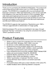
.../2 compatible. Switching between computers. 1 DKVM-CB § Supports Monitor resolutions of up to control 2/4 computers from one console. § Works with DOS, Windows, OS/2, UNIX, Linux etc. § No drivers or other additional software required. § Keyboard and mouse emulation allows error-free boot-up to 1920 x 1440 are not compatible with PS/2. This product will ensure easy and accurate control over 2 or 4 PCs through keyboard "Hot Key" commands or...
.../2 compatible. Switching between computers. 1 DKVM-CB § Supports Monitor resolutions of up to control 2/4 computers from one console. § Works with DOS, Windows, OS/2, UNIX, Linux etc. § No drivers or other additional software required. § Keyboard and mouse emulation allows error-free boot-up to 1920 x 1440 are not compatible with PS/2. This product will ensure easy and accurate control over 2 or 4 PCs through keyboard "Hot Key" commands or...

Product Manual
Page 4
FRONT PANEL LAYOUT REAR PANEL LAYOUT Before you have the following contents of front and rear panel will explain how to connect the console and the computers to the DKVM-2/4, please make sure that everything is powered off. 2 Package Contents In addition to this User's Guide, please check that you start connecting your computers and console devices to the DKVM-4 switch unit. First the layout of this package... § DKVM-2/4 § Power Adapter Hardware Installation This section will be shown.
FRONT PANEL LAYOUT REAR PANEL LAYOUT Before you have the following contents of front and rear panel will explain how to connect the console and the computers to the DKVM-2/4, please make sure that everything is powered off. 2 Package Contents In addition to this User's Guide, please check that you start connecting your computers and console devices to the DKVM-4 switch unit. First the layout of this package... § DKVM-2/4 § Power Adapter Hardware Installation This section will be shown.
Product Manual
Page 5
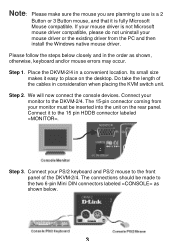
... must be made to the two 6-pin Mini DIN connectors labeled =CONSOLE= as shown, otherwise, keyboard and/or mouse errors may occur. Connect your mouse driver is fully Microsoft Mouse compatible. Place the DKVM-2/4 in consideration when placing the KVM switch unit. Note: Please make sure the mouse you are planning to use is a 2 Button or 3 Button mouse, and that it is...
... must be made to the two 6-pin Mini DIN connectors labeled =CONSOLE= as shown, otherwise, keyboard and/or mouse errors may occur. Connect your mouse driver is fully Microsoft Mouse compatible. Place the DKVM-2/4 in consideration when placing the KVM switch unit. Note: Please make sure the mouse you are planning to use is a 2 Button or 3 Button mouse, and that it is...
Product Manual
Page 6
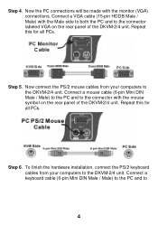
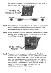
... rear panel of the DKVM-2/4 unit. Repeat this for all PCs. Step 4. To finish the hardware installation, connect the PS/2 keyboard cables from your computers to the DKVM-2/4 unit. Connect a keyboard cable (6-pin Mini DIN Male / Male) to the PC and to the connector with the monitor (VGA) connections. Step 5. Repeat this for all PCs. Step 6. Now connect the PS/2 mouse cables from your computers...
... rear panel of the DKVM-2/4 unit. Repeat this for all PCs. Step 4. To finish the hardware installation, connect the PS/2 keyboard cables from your computers to the DKVM-2/4 unit. Connect a keyboard cable (6-pin Mini DIN Male / Male) to the PC and to the connector with the monitor (VGA) connections. Step 5. Repeat this for all PCs. Step 6. Now connect the PS/2 mouse cables from your computers...
Product Manual
Page 7
... cables should be shown on the monitor. Step 7. Step 8. You will see if the mouse and keyboard work after the system has booted up. Now power up , and you find errors, re-check all PCs. Now make sure to verify all computers simultaneously. Step 9. Switch on your monitor. The first computer that is OK, use the same type of the DKVM-2/4 unit. If this manual...
... cables should be shown on the monitor. Step 7. Step 8. You will see if the mouse and keyboard work after the system has booted up. Now power up , and you find errors, re-check all PCs. Now make sure to verify all computers simultaneously. Step 9. Switch on your monitor. The first computer that is OK, use the same type of the DKVM-2/4 unit. If this manual...

Product Manual
Page 8
... is normal and is the active system. If you switch PC ports on the unit, or make use of KVM switch or run hot key) while the computers are under their boot-up process, each PC will cause communication errors or initialization failures between PC and keyboard or mouse. Using the DKVM-2/4 The DKVM-2/4 switch unit provides two ways to another computer. "SELECT...
... is normal and is the active system. If you switch PC ports on the unit, or make use of KVM switch or run hot key) while the computers are under their boot-up process, each PC will cause communication errors or initialization failures between PC and keyboard or mouse. Using the DKVM-2/4 The DKVM-2/4 switch unit provides two ways to another computer. "SELECT...
Product Manual
Page 9
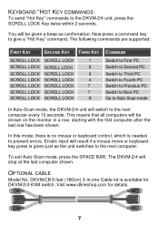
... mode, press the SPACE BAR. OPTIONAL CABLE Model No. You will be given a beep as the unit switches to prevent errors. SCROLL LOCK SCROLL LOCK ? This means that all computers will be shown on the monitor in -one has been shown. KEYBOARD "HOT KEY COMMANDS To send "Hot Key" commands to give a "Hot Key" command. Visit www.dlinkshop.com for DKVM-2/4 KVM switch...
... mode, press the SPACE BAR. OPTIONAL CABLE Model No. You will be given a beep as the unit switches to prevent errors. SCROLL LOCK SCROLL LOCK ? This means that all computers will be shown on the monitor in -one has been shown. KEYBOARD "HOT KEY COMMANDS To send "Hot Key" commands to give a "Hot Key" command. Visit www.dlinkshop.com for DKVM-2/4 KVM switch...
Product Manual
Page 10
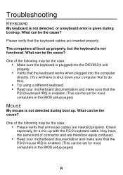
... all mouse cables are inserted properly. Check especially for most computers in the BIOS setup pages) MOUSE My mouse is not detected during boot-up properly, but the keyboard is enabled. (This can be set for a mix-up . Troubleshooting KEYBOARD My keyboard is not detected, or a keyboard error is given during boot up with the PS/2 keyboard cable, they have...
... all mouse cables are inserted properly. Check especially for most computers in the BIOS setup pages) MOUSE My mouse is not detected during boot-up properly, but the keyboard is enabled. (This can be set for a mix-up . Troubleshooting KEYBOARD My keyboard is not detected, or a keyboard error is given during boot up with the PS/2 keyboard cable, they have...

Product Manual
Page 11
... other. § Try resetting the mouse by unplugging it must be set to PS/2 mode and the correct serial mouse to verify you are not supported by the DKVM-2/4 unit. § Do not move the mouse or press any mouse buttons while switching from the DKVM-2/4 unit for a standard PS/2 or fully Microsoft compatible PS/2 mouse. PS/2 adapter will now be...
... other. § Try resetting the mouse by unplugging it must be set to PS/2 mode and the correct serial mouse to verify you are not supported by the DKVM-2/4 unit. § Do not move the mouse or press any mouse buttons while switching from the DKVM-2/4 unit for a standard PS/2 or fully Microsoft compatible PS/2 mouse. PS/2 adapter will now be...
Product Manual
Page 12
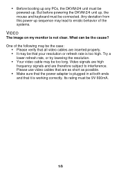
...high frequency signals and are inserted properly. § It may be too long. Please use video cables that are as short as possible. § Make sure that the power adapter is plugged in at both ends and that your resolution or refresh rate is too ...working correctly. Any deviation from this power-up sequence may be that it is not clear. But before powering the DKVM-2/4 unit up, the mouse and keyboard must be powered-up. § Before booting up any PCs, the DKVM-2/4 unit must be connected. Try a lower refresh rate, or try lowering the resolution. § Your video cable...
...high frequency signals and are inserted properly. § It may be too long. Please use video cables that are as short as possible. § Make sure that the power adapter is plugged in at both ends and that your resolution or refresh rate is too ...working correctly. Any deviation from this power-up sequence may be that it is not clear. But before powering the DKVM-2/4 unit up, the mouse and keyboard must be powered-up. § Before booting up any PCs, the DKVM-2/4 unit must be connected. Try a lower refresh rate, or try lowering the resolution. § Your video cable...
Product Manual
Page 13
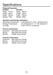
Specifications Physical Properties: DKVM-2 DKVM-4 Width: 119mm Width: 185mm Height: 46mm Height: 46mm Depth: 105mm Depth: 105mm Weight: 478g Weight: 684g Operation and Storage parameters: Operating Temperature: 0~40 Degrees C (32 to 104 Degrees F) Storage Temperature: -20~60 Degrees C (-4~140 Degrees F) Humidity: 0~80% RH non condensing PC port connections Keyboard: Mini DIN 6 pin Female Mouse: Mini DIN 6 pin Female Monitor: HDDB 15 pin Female Console connections Keyboard: Mini DIN 6 pin Female Mouse: Mini DIN 6 pin Female Monitor: HDDB 15 pin Female 11
Specifications Physical Properties: DKVM-2 DKVM-4 Width: 119mm Width: 185mm Height: 46mm Height: 46mm Depth: 105mm Depth: 105mm Weight: 478g Weight: 684g Operation and Storage parameters: Operating Temperature: 0~40 Degrees C (32 to 104 Degrees F) Storage Temperature: -20~60 Degrees C (-4~140 Degrees F) Humidity: 0~80% RH non condensing PC port connections Keyboard: Mini DIN 6 pin Female Mouse: Mini DIN 6 pin Female Monitor: HDDB 15 pin Female Console connections Keyboard: Mini DIN 6 pin Female Mouse: Mini DIN 6 pin Female Monitor: HDDB 15 pin Female 11

Product Manual
Page 14
... used in a residential installation. If this product may cause undesired operation. You are designed to provide reasonable protection against harmful interference in accordance with the instructions, may cause harmful interference to radio communications. This device complies with Part 15 of the following two conditions: (1) This device may not cause harmful interference, and (2) This device must be determined by turning...
... used in a residential installation. If this product may cause undesired operation. You are designed to provide reasonable protection against harmful interference in accordance with the instructions, may cause harmful interference to radio communications. This device complies with Part 15 of the following two conditions: (1) This device may not cause harmful interference, and (2) This device must be determined by turning...
Product Manual
Page 16
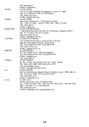
...095-737-3492 FAX: 7-095-737-3390 URL: www.dlink.ru E- MAIL: [email protected] D-LINK U.S.A. 53 Discovery Drive, Irvine, CA 92618 USA TEL: 1-949-788-0805 FAX: 1-949-753-7033 INFO LINE: 1-800-326-1688 BBS: 1-949-455-1779, 1-949-455-9616 URL: www.dlink.com E- ...D-LINK SOUTH AFRICA 102-106 Witchhazel Avenue, Einetein Park 2, Block B, Highveld Technopark Centurion, South Africa TEL: 27(0)126652165 FAX: 27(0)126652186 URL: www.d-link.co.za E- MAIL: [email protected] D-LINK EUROPE 4th Floor, Merit House, Edgware Road, Colindale, London, NW9 5AB, U.K. MAIL: [email protected], support@...
...095-737-3492 FAX: 7-095-737-3390 URL: www.dlink.ru E- MAIL: [email protected] D-LINK U.S.A. 53 Discovery Drive, Irvine, CA 92618 USA TEL: 1-949-788-0805 FAX: 1-949-753-7033 INFO LINE: 1-800-326-1688 BBS: 1-949-455-1779, 1-949-455-9616 URL: www.dlink.com E- ...D-LINK SOUTH AFRICA 102-106 Witchhazel Avenue, Einetein Park 2, Block B, Highveld Technopark Centurion, South Africa TEL: 27(0)126652165 FAX: 27(0)126652186 URL: www.d-link.co.za E- MAIL: [email protected] D-LINK EUROPE 4th Floor, Merit House, Edgware Road, Colindale, London, NW9 5AB, U.K. MAIL: [email protected], support@...

Product Manual
Page 17
... to 12:00am EST D-Link Technical Support over the Internet: http://support.dlink.ca email:support@dlink.ca When contacting technical support, please provide the following information: · Serial number of the warranty period on the D-Link website. and Canadian customers can find software updates and user documentation on this product. D-Link provides free technical support for the duration of the unit · Model number or product name · Software type and version number U.S.
... to 12:00am EST D-Link Technical Support over the Internet: http://support.dlink.ca email:support@dlink.ca When contacting technical support, please provide the following information: · Serial number of the warranty period on the D-Link website. and Canadian customers can find software updates and user documentation on this product. D-Link provides free technical support for the duration of the unit · Model number or product name · Software type and version number U.S.
Product Manual
Page 18
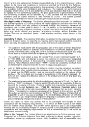
... its documentation. Military Installations, or addresses with software that substantially conforms to D-Link's functional specifications for the Software or to refund the portion of the actual purchase price paid . Subject to the terms and conditions set forth below ("Hardware") will be free from material defects in workmanship and materials under normal use from the date of original retail purchase of the product...
... its documentation. Military Installations, or addresses with software that substantially conforms to D-Link's functional specifications for the Software or to refund the portion of the actual purchase price paid . Subject to the terms and conditions set forth below ("Hardware") will be free from material defects in workmanship and materials under normal use from the date of original retail purchase of the product...
Product Manual
Page 19
... contrary. Link in writing, the replacement Software is provided only to the original licensee, and is subject to the terms and conditions of D-Link. The repaired or replaced packages will ship the product to D-Link Systems, Inc., 17595 Mt. The product owner agrees to pay D-Link's reasonable handling and return shipping charges for which a refund is not visible from D-Link Technical Support at...
... contrary. Link in writing, the replacement Software is provided only to the original licensee, and is subject to the terms and conditions of D-Link. The repaired or replaced packages will ship the product to D-Link Systems, Inc., 17595 Mt. The product owner agrees to pay D-Link's reasonable handling and return shipping charges for which a refund is not visible from D-Link Technical Support at...

Product Manual
Page 20
... products or services provided by D-Link Corporation/D-Link Systems, Inc. Copyright Statement: No part of California. Some states do not allow exclusion or limitation of God, failures due to act of incidental or consequential damages, or limitations on your Product can be reproduced in the documentation for the product, or if the model or serial number has been altered, tampered with, defaced or removed; repair...
... products or services provided by D-Link Corporation/D-Link Systems, Inc. Copyright Statement: No part of California. Some states do not allow exclusion or limitation of God, failures due to act of incidental or consequential damages, or limitations on your Product can be reproduced in the documentation for the product, or if the model or serial number has been altered, tampered with, defaced or removed; repair...
Product Manual
Page 21
...digital device, pursuant to take adequate measures. If this product may cause radio interference, in accordance with the limits for help. FCC Statement: This equipment has been tested and found to comply with the instructions, may be determined by turning the equipment off and on, the user ... the receiving antenna. • Increase the separation between the equipment and receiver. • Connect the equipment into an outlet on a circuit different from that to which can radiate radio frequency energy and, if not installed and used in which case the user may cause harmful...
...digital device, pursuant to take adequate measures. If this product may cause radio interference, in accordance with the limits for help. FCC Statement: This equipment has been tested and found to comply with the instructions, may be determined by turning the equipment off and on, the user ... the receiving antenna. • Increase the separation between the equipment and receiver. • Connect the equipment into an outlet on a circuit different from that to which can radiate radio frequency energy and, if not installed and used in which case the user may cause harmful...


