
Product Manual
Page 3
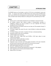
... the user a visual interface to naming and selecting computers l On-Screen Display, push button or keyboard "Hot Key" commands switching l AutoScan mode for even more convenience l Audible feedback when switching l Recalls CAPS LOCK, NUM LOCK and SCROLL LOCK keys' status for each channel contains a microprocessor emulation to 1600 x 1200 resolution support l Integrated mouse conversion technology allows connection of AT type computers that have serial mouse ports while using...
... the user a visual interface to naming and selecting computers l On-Screen Display, push button or keyboard "Hot Key" commands switching l AutoScan mode for even more convenience l Audible feedback when switching l Recalls CAPS LOCK, NUM LOCK and SCROLL LOCK keys' status for each channel contains a microprocessor emulation to 1600 x 1200 resolution support l Integrated mouse conversion technology allows connection of AT type computers that have serial mouse ports while using...
Product Manual
Page 4
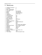
... Button q Hot Key : Yes q Switching Confirmation : Buzzer q Keyboard state : Saved and Restored q Keyboard : PS/2 q Mouse : PS/2 q Monitor : VGA, SVGA, XGA, MultiSync q Display Data Channel : DDC1, DDC2B, DDC2AB q Resolution : 1600 x 1200 q Bandwidth : 180M Hz q Enclosure : Metal q Storage (Celsius) : 0 ~ 70 q Dimension (LxWxH cm) : 44.1 x 18.45 x 7.25 q Weight (g) : 2950 q Power Supply : 18W, Universal AC input ~2 ~ INTRODUCTION 1.1 SPECIFICATION q Computer Connections : 8 q Port LEDs : 8 q Bank 7-segment LED : 1 q Port...
... Button q Hot Key : Yes q Switching Confirmation : Buzzer q Keyboard state : Saved and Restored q Keyboard : PS/2 q Mouse : PS/2 q Monitor : VGA, SVGA, XGA, MultiSync q Display Data Channel : DDC1, DDC2B, DDC2AB q Resolution : 1600 x 1200 q Bandwidth : 180M Hz q Enclosure : Metal q Storage (Celsius) : 0 ~ 70 q Dimension (LxWxH cm) : 44.1 x 18.45 x 7.25 q Weight (g) : 2950 q Power Supply : 18W, Universal AC input ~2 ~ INTRODUCTION 1.1 SPECIFICATION q Computer Connections : 8 q Port LEDs : 8 q Bank 7-segment LED : 1 q Port...
Product Manual
Page 5
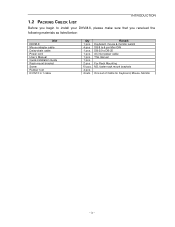
INTRODUCTION 1.2 PACKING CHECK LIST Before you begin to install your DKVM-8, please make sure that you received the following materials as listed below: Item DKVM-8 Mouse adapter cable Daisy-chain cable Power cord User's Manual Quick lnstallation Guide Rack mount bracket Screw Rubber foot K/V/M 3 in 1 cable Qty 1 pcs. 4 pcs. 1 pcs. 1 pcs. 1 pcs. 1 pcs. 2 pcs. 10 pcs. 4 pcs. 2 sets Remark Keyboard, mouse & monitor switch DB-9 to 6-pin Mini-DIN DB-25 to DB-25 AC inlet power cable This manual For Rack Mounting M3, fasten rack mount brackets One set of Cable for Keyboard, Mouse, Monitor ~ 3 ~
INTRODUCTION 1.2 PACKING CHECK LIST Before you begin to install your DKVM-8, please make sure that you received the following materials as listed below: Item DKVM-8 Mouse adapter cable Daisy-chain cable Power cord User's Manual Quick lnstallation Guide Rack mount bracket Screw Rubber foot K/V/M 3 in 1 cable Qty 1 pcs. 4 pcs. 1 pcs. 1 pcs. 1 pcs. 1 pcs. 2 pcs. 10 pcs. 4 pcs. 2 sets Remark Keyboard, mouse & monitor switch DB-9 to 6-pin Mini-DIN DB-25 to DB-25 AC inlet power cable This manual For Rack Mounting M3, fasten rack mount brackets One set of Cable for Keyboard, Mouse, Monitor ~ 3 ~
Product Manual
Page 7
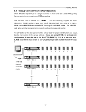
... connects to the console keyboard, mouse and monitor. See the next section for more units (for a total of 16), giving the user control over a maximum of 16 banks. BANK numbers range from 1 through F are using DKVM-8 in a single unit configuration, it must be set correctly for proper identification and usage. Bank F (Slave) 121 122 123 124 125 126 127 128 ~ 5 ~ INSTALLATION...
... connects to the console keyboard, mouse and monitor. See the next section for more units (for a total of 16), giving the user control over a maximum of 16 banks. BANK numbers range from 1 through F are using DKVM-8 in a single unit configuration, it must be set correctly for proper identification and usage. Bank F (Slave) 121 122 123 124 125 126 127 128 ~ 5 ~ INSTALLATION...
Product Manual
Page 8
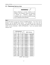
If you are reserved, default setting is "ON" .) DIP-Switch NO. 3 4 5 BANK Address ON ON ON BANK 0 MASTER OFF ON ON BANK 1 SLAVE ON OFF ON BANK 2 SLAVE OFF OFF ON BANK 3 ...DKVM-8 or the computers, make sure everything is down ~6 ~ Step 1 Set the DIP-switch for more information. (NOTE: DIP-Switch No. 1 and 2 are using will be Daisy-Chained off . Please refer to the previous section for Auto-scan Interval and BANK Address. If the DKVM-8 you have only one DKVM-8, use a unique slave setting. INSTALLATION 2.3 HARDWARE INSTALLATION WARNING! Before attempting to connect...
If you are reserved, default setting is "ON" .) DIP-Switch NO. 3 4 5 BANK Address ON ON ON BANK 0 MASTER OFF ON ON BANK 1 SLAVE ON OFF ON BANK 2 SLAVE OFF OFF ON BANK 3 ...DKVM-8 or the computers, make sure everything is down ~6 ~ Step 1 Set the DIP-switch for more information. (NOTE: DIP-Switch No. 1 and 2 are using will be Daisy-Chained off . Please refer to the previous section for Auto-scan Interval and BANK Address. If the DKVM-8 you have only one DKVM-8, use a unique slave setting. INSTALLATION 2.3 HARDWARE INSTALLATION WARNING! Before attempting to connect...
Product Manual
Page 9
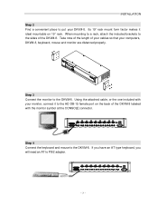
... to the sides of your cables so that your DKVM-8. Using the attached cable, or the one included with your monitor, connect it ideal mountable on the back of the DKVM-8 labeled with the monitor symbol at the CONSOLE connector. Its 19" rack mount form factor makes it to the DKVM-8. Step 3 Connect the monitor to PS/2 adapter. Take note of the length...
... to the sides of your cables so that your DKVM-8. Using the attached cable, or the one included with your monitor, connect it ideal mountable on the back of the DKVM-8 labeled with the monitor symbol at the CONSOLE connector. Its 19" rack mount form factor makes it to the DKVM-8. Step 3 Connect the monitor to PS/2 adapter. Take note of the length...
Product Manual
Page 10
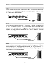
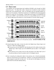
... 3 45 6 SW AC LINE 90-240 VAC Step 7 Connect the first computer's keyboard cable to the PC1 DB-9 serial mouse port on the back of DKVM-8. If using a PS/2 cable connect one end to the PS/2 mouse port on the computer, and the other end to the DKVM-8. INSTALLATION Step 5 Connect the first computer's VGA cable to AT keyboard adapter. Back of DKVM-8. Using the VGA cable connect the male end...
... 3 45 6 SW AC LINE 90-240 VAC Step 7 Connect the first computer's keyboard cable to the PC1 DB-9 serial mouse port on the back of DKVM-8. If using a PS/2 cable connect one end to the PS/2 mouse port on the computer, and the other end to the DKVM-8. INSTALLATION Step 5 Connect the first computer's VGA cable to AT keyboard adapter. Back of DKVM-8. Using the VGA cable connect the male end...
Product Manual
Page 11
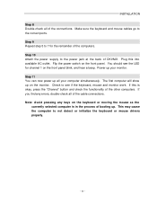
... is okay, press the "Channel" button and check the functionality of the cable connections. Plug this is in the process of the connections. Make sure the keyboard and mouse cables go to not detect or initialize the keyboard or mouse drivers properly. ~ 9 ~ Step 10 Attach the power supply to see the LED for the remainder of DKVM-8. INSTALLATION Step 8 Double-check all of booting up. This may cause...
... is okay, press the "Channel" button and check the functionality of the cable connections. Plug this is in the process of the connections. Make sure the keyboard and mouse cables go to not detect or initialize the keyboard or mouse drivers properly. ~ 9 ~ Step 10 Attach the power supply to see the LED for the remainder of DKVM-8. INSTALLATION Step 8 Double-check all of booting up. This may cause...
Product Manual
Page 12
...-switch settings. Recall that the power supply be used with additional DKVM-8 units through F). INSTALLATION 2.4 DAISY-CHAIN The DKVM-8 can be cascaded together for control over 32 computers. l Using the daisy-chain cable, connect one end to the "Master Input / Slave Output" port of this section for more information on the MASTER unit must be set to BANK 0, and the SLAVE units set to the example...
...-switch settings. Recall that the power supply be used with additional DKVM-8 units through F). INSTALLATION 2.4 DAISY-CHAIN The DKVM-8 can be cascaded together for control over 32 computers. l Using the daisy-chain cable, connect one end to the "Master Input / Slave Output" port of this section for more information on the MASTER unit must be set to BANK 0, and the SLAVE units set to the example...
Product Manual
Page 13
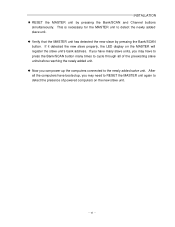
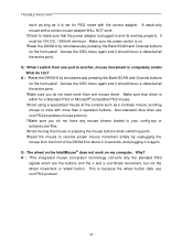
...has detected the new slave by pressing the Bank/SCAN and Channel buttons simultaneously. l Now you can power up , you may need to RESET the MASTER unit again to detect the newly added slave unit. If you have many times to the newly added salve unit. This is necessary for ...the Bank/SCAN button many slave units, you may have booted up the computers connected to cycle through all of powered computers on the MASTER will register the slave unit's bank address. If it detected the new slave properly, the LED display on the new slave unit. ~ 11 ~ INSTALLATION l RESET the MASTER ...
...has detected the new slave by pressing the Bank/SCAN and Channel buttons simultaneously. l Now you can power up , you may need to RESET the MASTER unit again to detect the newly added slave unit. If you have many times to the newly added salve unit. This is necessary for ...the Bank/SCAN button many slave units, you may have booted up the computers connected to cycle through all of powered computers on the MASTER will register the slave unit's bank address. If it detected the new slave properly, the LED display on the new slave unit. ~ 11 ~ INSTALLATION l RESET the MASTER ...
Product Manual
Page 15
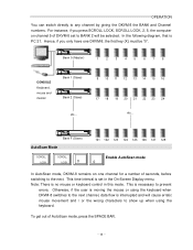
... 127 128 Enable AutoScan mode 0 In AutoScan mode, DKVM-8 remains on channel 5 of DKVM-8 set in this mode. To get out of seconds, before switching to any channel by giving the DKVM-8 the BANK and Channel numbers. In the following diagram, that is no mouse or keyboard control in the On...channel, data flow is interrupted and will be "0". This time interval is moving the mouse or using the keyboard. Otherwise, if the user is set to BANK 2 will cause erratic mouse movement and / or the wrong characters to show up when using the keyboard when DKVM-8 switches to prevent errors...
... 127 128 Enable AutoScan mode 0 In AutoScan mode, DKVM-8 remains on channel 5 of DKVM-8 set in this mode. To get out of seconds, before switching to any channel by giving the DKVM-8 the BANK and Channel numbers. In the following diagram, that is no mouse or keyboard control in the On...channel, data flow is interrupted and will be "0". This time interval is moving the mouse or using the keyboard. Otherwise, if the user is set to BANK 2 will cause erratic mouse movement and / or the wrong characters to show up when using the keyboard when DKVM-8 switches to prevent errors...
Product Manual
Page 16
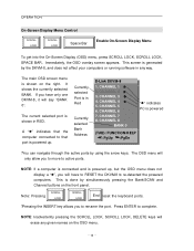
... Bank Address D-Link DKVM-8 1. CHANNEL 1 ® 2. CHANNEL 4 ® 5. This is shown in RED. Currently selected Port is in any given names on the OSD menu. ~ 14 ~ CHANNEL 2 ® 3. CHANNEL 6 7. A "®" indicates that the computer connected to that port is powered (TAB): FUNCTION/H ELP :PgUp :PgDn ?You can navigate through the active ports by simultaneously pressing the Bank/SCAN and Channel buttons on the right. CHANNEL 5 6. CHANNEL 8 BANK...
... Bank Address D-Link DKVM-8 1. CHANNEL 1 ® 2. CHANNEL 4 ® 5. This is shown in RED. Currently selected Port is in any given names on the OSD menu. ~ 14 ~ CHANNEL 2 ® 3. CHANNEL 6 7. A "®" indicates that the computer connected to that port is powered (TAB): FUNCTION/H ELP :PgUp :PgDn ?You can navigate through the active ports by simultaneously pressing the Bank/SCAN and Channel buttons on the right. CHANNEL 5 6. CHANNEL 8 BANK...
Product Manual
Page 17
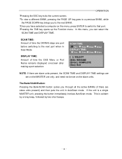
..., while the PAGE DOWN key brings you to that port. ?Pressing the TAB key opens up the Function menu. SCAN TIME: Amount of time the DKVM-8 stays one port before switching to the next port when in Scan Mode DISPLAY TIME: Amount of time the OSD Menu or Port Name remains displayed on-screen after making a port selection SCAN TIME: 7se c 15sec DISPLAY TIME: 7sec 15sec 30sec 30sec...
..., while the PAGE DOWN key brings you to that port. ?Pressing the TAB key opens up the Function menu. SCAN TIME: Amount of time the DKVM-8 stays one port before switching to the next port when in Scan Mode DISPLAY TIME: Amount of time the OSD Menu or Port Name remains displayed on-screen after making a port selection SCAN TIME: 7se c 15sec DISPLAY TIME: 7sec 15sec 30sec 30sec...
Product Manual
Page 18
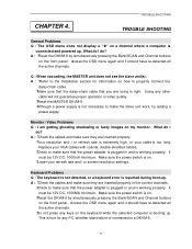
... or connected to make the slave unit work, try adding a power supply. Monitor / Video Problems Q : I do ? A : ?Check the cables and make sure that the power adapter is plugged in and is connected and powered up . It must be 12V DC, 1000MA minimum. A : ?Reset the DKVM-8 by simultaneously pressing the Bank/SCAN and Channel buttons on the keyboard while the selected computer is right. CHAPTER 4. A : ?Refer to the Installation section...
... or connected to make the slave unit work, try adding a power supply. Monitor / Video Problems Q : I do ? A : ?Check the cables and make sure that the power adapter is plugged in and is connected and powered up . It must be 12V DC, 1000MA minimum. A : ?Reset the DKVM-8 by simultaneously pressing the Bank/SCAN and Channel buttons on the keyboard while the selected computer is right. CHAPTER 4. A : ?Refer to the Installation section...
Product Manual
Page 19
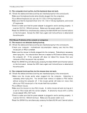
... Problems at the console or computers Q : The mouse is on. ?Reset the DKVM-8 by simultaneously pressing the Back/SCAN and Channel buttons on the front panel. Make sure the power switch is not detected during boot-up. TROUBLE SHOOTING Q : The computers boot up fine, but the mouse does not work. A : ?Check the cables and make sure they are inserted properly in the correct ports. ?Make sure the mouse works...
... Problems at the console or computers Q : The mouse is on. ?Reset the DKVM-8 by simultaneously pressing the Back/SCAN and Channel buttons on the front panel. Make sure the power switch is not detected during boot-up. TROUBLE SHOOTING Q : The computers boot up fine, but the mouse does not work. A : ?Check the cables and make sure they are inserted properly in the correct ports. ?Make sure the mouse works...
Product Manual
Page 20
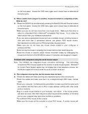
... cable. ?Check your computer / motherboard documentation to make sure that it should have re-detected all the active ports. ?Make sure you are no serial mouse drivers installed, or the serial port on your config.sys or autoexec.bat files. ?Avoid moving the mouse or pressing the mouse buttons when switching ports. ?Reset the mouse to obtain the latest version from one mouse driver. Make sure that there are using the serial...
... cable. ?Check your computer / motherboard documentation to make sure that it should have re-detected all the active ports. ?Make sure you are no serial mouse drivers installed, or the serial port on your config.sys or autoexec.bat files. ?Avoid moving the mouse or pressing the mouse buttons when switching ports. ?Reset the mouse to obtain the latest version from one mouse driver. Make sure that there are using the serial...
Product Manual
Page 21
.... ?Reset the DKVM-8 by simultaneously pressing the Bank/SCAN and Channel buttons on the front panel. Make sure the power switch is because the wheel button data use non-PS/2 proprietary mouse protocol. ?Make sure you do not have any mouse drivers loaded in your config.sys or autoexec.bat files. ?Avoid moving the mouse or pressing the mouse buttons when switching ports. ?Reset the mouse to make...
.... ?Reset the DKVM-8 by simultaneously pressing the Bank/SCAN and Channel buttons on the front panel. Make sure the power switch is because the wheel button data use non-PS/2 proprietary mouse protocol. ?Make sure you do not have any mouse drivers loaded in your config.sys or autoexec.bat files. ?Avoid moving the mouse or pressing the mouse buttons when switching ports. ?Reset the mouse to make...

Product Manual
Page 23
...) 361-5265 Monday to Friday 7:30am to 12:00am EST D-Link Technical Support over the Internet: http://support.dlink.ca email:support@dlink.ca When contacting technical support, please provide the following information: · Serial number of the warranty period on the D-Link website. U.S. D-Link provides free technical support for the duration of the unit · Model number or product name · Software type and version number D-Link Systems, Inc.
...) 361-5265 Monday to Friday 7:30am to 12:00am EST D-Link Technical Support over the Internet: http://support.dlink.ca email:support@dlink.ca When contacting technical support, please provide the following information: · Serial number of the warranty period on the D-Link website. U.S. D-Link provides free technical support for the duration of the unit · Model number or product name · Software type and version number D-Link Systems, Inc.
Product Manual
Page 24
... care, repair or service in any company, we will be refunded by D-Link at D-Link's option, to replace the non-conforming Software (or defective media) with proof of purchase of the product (such as a copy of D-Link and its suppliers under this Limited Warranty will be free from material defects in the documentation for the product, or if the model or serial number has...
... care, repair or service in any company, we will be refunded by D-Link at D-Link's option, to replace the non-conforming Software (or defective media) with proof of purchase of the product (such as a copy of D-Link and its suppliers under this Limited Warranty will be free from material defects in the documentation for the product, or if the model or serial number has...
Product Manual
Page 25
...harmful interference in a residential installation. Copyright Statement: No part of this publication or documentation accompanying this product may be determined by turning the equipment off and on, the user is encouraged to try to make any derivative such as ...WORK STOPPAGE, COMPUTER FAILURE OR MALFUNCTION, FAILURE OF OTHER EQUIPMENT OR COMPUTER PROGRAMS TO WHICH D-LINK'S PRODUCT IS CONNECTED WITH, LOSS OF INFORMATION OR DATA CONTAINED IN, STORED ON, OR INTEGRATED WITH ANY PRODUCT RETURNED TO D-LINK FOR WARRANTY SERVICE) RESULTING FROM THE USE OF THE PRODUCT, RELATING TO WARRANTY SERVICE...
...harmful interference in a residential installation. Copyright Statement: No part of this publication or documentation accompanying this product may be determined by turning the equipment off and on, the user is encouraged to try to make any derivative such as ...WORK STOPPAGE, COMPUTER FAILURE OR MALFUNCTION, FAILURE OF OTHER EQUIPMENT OR COMPUTER PROGRAMS TO WHICH D-LINK'S PRODUCT IS CONNECTED WITH, LOSS OF INFORMATION OR DATA CONTAINED IN, STORED ON, OR INTEGRATED WITH ANY PRODUCT RETURNED TO D-LINK FOR WARRANTY SERVICE) RESULTING FROM THE USE OF THE PRODUCT, RELATING TO WARRANTY SERVICE...


