
Planning Guides
Page 1
... Power cord in Gas Cooktops warning • Observe all governing codes and ordinances during planning and installation. Document # PG04-006 DCT305, DCT365 30" and 36" Wide, Distinctive Series Drop-in Front of cooktop 1/2" male NPT gas inlet* 1 3/4" (4.4 cm) Chassis 1/2" male NPT gas inlet Power cord 42" (106.7 cm) long Utility Locations 1 3/4" (4.4 cm) 2" (5.1 cm) Top panel overhang *Gas inlet protudes 1/2" (1.3 cm) from bottom Utility Dimensions Specifications subject to change...
... Power cord in Gas Cooktops warning • Observe all governing codes and ordinances during planning and installation. Document # PG04-006 DCT305, DCT365 30" and 36" Wide, Distinctive Series Drop-in Front of cooktop 1/2" male NPT gas inlet* 1 3/4" (4.4 cm) Chassis 1/2" male NPT gas inlet Power cord 42" (106.7 cm) long Utility Locations 1 3/4" (4.4 cm) 2" (5.1 cm) Top panel overhang *Gas inlet protudes 1/2" (1.3 cm) from bottom Utility Dimensions Specifications subject to change...
Planning Guides
Page 2
... manual shut-off valve must be installed in accordance with a 3/4" male NPT fitting. DCT304_NG DCT365_NG DCT304_LP DCT365_LP Gas type Natural LP gas Manifold pressure 5" water column 10" water column Min. www.dacor.com Phone: (800) 7943-.010993 See the Gas and Electrical Requirements table on this appliance should be done in the gas line that the cooktop being provided (natural gas or LP gas). Use only the regulator provided. Gas and Electrical Requirements* * The electrical...
... manual shut-off valve must be installed in accordance with a 3/4" male NPT fitting. DCT304_NG DCT365_NG DCT304_LP DCT365_LP Gas type Natural LP gas Manifold pressure 5" water column 10" water column Min. www.dacor.com Phone: (800) 7943-.010993 See the Gas and Electrical Requirements table on this appliance should be done in the gas line that the cooktop being provided (natural gas or LP gas). Use only the regulator provided. Gas and Electrical Requirements* * The electrical...
Planning Guides
Page 3
... the routing of gas and electrical service behind it is in place. Raised Vent Compatibility Model DCT305 is not compatible with an overhead range hood, check the hood specifications for minimum required clearances. 3 This specification does not apply for cabinets located greater than a horizontal distance of 5 1/2" (14.0 cm) from drafts that may be caused by reaching over a hot appliance, avoid locating cabinet storage space directly above the cooktop. • Failure to...
... the routing of gas and electrical service behind it is in place. Raised Vent Compatibility Model DCT305 is not compatible with an overhead range hood, check the hood specifications for minimum required clearances. 3 This specification does not apply for cabinets located greater than a horizontal distance of 5 1/2" (14.0 cm) from drafts that may be caused by reaching over a hot appliance, avoid locating cabinet storage space directly above the cooktop. • Failure to...
Installation Instructions
Page 2
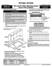
... Safety Instructions 1 General Safety Precautions 2 Installation Specifications 3 Product Dimensions 3 Electrical Requirements 4 Gas Supply Requirements 4 Cabinet and Countertop Layout 5 Installation Instructions 7 Verify Package Contents 7 Installing the Cooktop 7 Connecting the Gas Line 7 Installing the Burner Components 8 Verifying Proper Operation 9 Installation Checklist 10 Wiring Diagram 11 Before You Begin... The model and serial number are subject to specifications. © 2011 Dacor, all rights reserved. Friday 6:00 a.m. to Dacor appliances under warranty only...
... Safety Instructions 1 General Safety Precautions 2 Installation Specifications 3 Product Dimensions 3 Electrical Requirements 4 Gas Supply Requirements 4 Cabinet and Countertop Layout 5 Installation Instructions 7 Verify Package Contents 7 Installing the Cooktop 7 Connecting the Gas Line 7 Installing the Burner Components 8 Verifying Proper Operation 9 Installation Checklist 10 Wiring Diagram 11 Before You Begin... The model and serial number are subject to specifications. © 2011 Dacor, all rights reserved. Friday 6:00 a.m. to Dacor appliances under warranty only...
Installation Instructions
Page 3
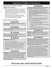
... WARNING - Aluminum foil linings may be burned. CALIFORNIA PROPOSITION 65 WARNING The burning of gas cooking fuel generates some by the State of grease and grime. California law requires businesses to cause cancer or reproductive harm. If the flames do not go out immediately, EVACUATE AND CALL THE FIRE DEPARTMENT. NEVER cover any electrical switch or use and care manual, ensuring you...
... WARNING - Aluminum foil linings may be burned. CALIFORNIA PROPOSITION 65 WARNING The burning of gas cooking fuel generates some by the State of grease and grime. California law requires businesses to cause cancer or reproductive harm. If the flames do not go out immediately, EVACUATE AND CALL THE FIRE DEPARTMENT. NEVER cover any electrical switch or use and care manual, ensuring you...
Installation Instructions
Page 4
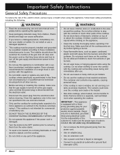
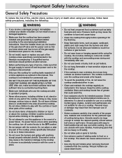
... electrical outlet. • Disconnect the power plug from the valve stems. • To avoid a fire hazard, do not use long curtains as pot holders. • Do not use . Important Safety Instructions General Safety Precautions To reduce the risk of fire, electric shock, serious injury or death when using the cooktop. Dacor strongly recommends the installation of a range hood in conjunction with the controls or touch other parts...
... electrical outlet. • Disconnect the power plug from the valve stems. • To avoid a fire hazard, do not use long curtains as pot holders. • Do not use . Important Safety Instructions General Safety Precautions To reduce the risk of fire, electric shock, serious injury or death when using the cooktop. Dacor strongly recommends the installation of a range hood in conjunction with the controls or touch other parts...

Installation Instructions
Page 5
.../32" (3.4 cm) Product Dimensions B Front View 21" (53.3 cm) 1 11/32" (3.4 cm) Front of unit Power cord in Front of cooktop 1/2" male NPT gas inlet* 1/2" male NPT gas inlet Power cord 42" (106.7 cm) long Utility Locations 1 3/4" (4.4 cm) Chassis 1 3/4" (4.4 cm) 2" (5.1 cm) Top panel overhang *Gas inlet protrudes 1/2" (1.3 cm) from bottom Utility Dimensions 3 Installation Specifications warning Observe all governing codes and ordinances during planning...
.../32" (3.4 cm) Product Dimensions B Front View 21" (53.3 cm) 1 11/32" (3.4 cm) Front of unit Power cord in Front of cooktop 1/2" male NPT gas inlet* 1/2" male NPT gas inlet Power cord 42" (106.7 cm) long Utility Locations 1 3/4" (4.4 cm) Chassis 1 3/4" (4.4 cm) 2" (5.1 cm) Top panel overhang *Gas inlet protrudes 1/2" (1.3 cm) from bottom Utility Dimensions 3 Installation Specifications warning Observe all governing codes and ordinances during planning...

Installation Instructions
Page 6
..., grounding electrical plug. Also, if operating the cooktop at an altitude above 4000 ft. (1219 m) make sure it is the owner's responsibility to make sure that the electrical service meets electrical requirements and that runs from the cooktop gas inlet to the gas shut off valve. • The regulator inlet (female) accommodates a 3/4" gas line. Use only the regulator provided. It can also accommodate a 1/2" gas line using the included reducer. Gas type Manifold pressure Min...
..., grounding electrical plug. Also, if operating the cooktop at an altitude above 4000 ft. (1219 m) make sure it is the owner's responsibility to make sure that the electrical service meets electrical requirements and that runs from the cooktop gas inlet to the gas shut off valve. • The regulator inlet (female) accommodates a 3/4" gas line. Use only the regulator provided. It can also accommodate a 1/2" gas line using the included reducer. Gas type Manifold pressure Min...
Installation Instructions
Page 7
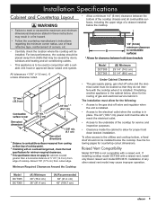
... the countertop manufacturer's instructions regarding the minimum corner radius, use of heat reflective tape, reinforcement of the cooktop for service and inspection purposes. • Clearance inside the cabinet to allow for proper hold down bracket installation. The installation must allow for the following pages for the routing of cooktop. The 42" (106.7 cm) power cord must be installed below the cooktop. If installing cooktop model DCT365 with a suitable vent hood or approved Dacor raised vent...
... the countertop manufacturer's instructions regarding the minimum corner radius, use of heat reflective tape, reinforcement of the cooktop for service and inspection purposes. • Clearance inside the cabinet to allow for proper hold down bracket installation. The installation must allow for the following pages for the routing of cooktop. The 42" (106.7 cm) power cord must be installed below the cooktop. If installing cooktop model DCT365 with a suitable vent hood or approved Dacor raised vent...

Installation Instructions
Page 8
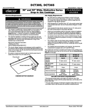
... 4 1/4" (10.8 cm) min. Check raised vent dimensions/specifications to clear stiffener ERV3615 raised vent. from mounting surface to F combustibles below cooktop chassis C E D 1 5/8" min. (4.1 cm) F Minimum distance to combustible side wall above countertop (both sides) Countertop Cutout Dimensions Installation Type DCT305* DCT365 with no raised vent DCT365 with ERV3615 raised vent (C) Minimum 3 1/4" (8.3 cm) 3 1/4" (8.3 cm) 3/8" (1.0 cm) * Model DCT305 is not compatible with ERV3615 Raised Vent 6 DCT365 Cooktop with a raised vent (D) 19 5/8" (49.9 cm) 19 5/8" (49.9 cm...
... 4 1/4" (10.8 cm) min. Check raised vent dimensions/specifications to clear stiffener ERV3615 raised vent. from mounting surface to F combustibles below cooktop chassis C E D 1 5/8" min. (4.1 cm) F Minimum distance to combustible side wall above countertop (both sides) Countertop Cutout Dimensions Installation Type DCT305* DCT365 with no raised vent DCT365 with ERV3615 raised vent (C) Minimum 3 1/4" (8.3 cm) 3 1/4" (8.3 cm) 3/8" (1.0 cm) * Model DCT305 is not compatible with ERV3615 Raised Vent 6 DCT365 Cooktop with a raised vent (D) 19 5/8" (49.9 cm) 19 5/8" (49.9 cm...

Installation Instructions
Page 9
... Connecting the Gas Line • Hold down brackets (2) • Grates (3) • Burner sets (5) • Gas pressure regulator with 3/4" to 1/2" reducer • Stainless steel cleaner Installing the Cooktop warning • Verify that the power supply meets the specifications on the gas supply valve and check all cooktop control valves to the OFF position. ◊ Turn on page 4 before proceeding. • To prevent damage to the gas pressure regulator, install it only after the cooktop is required. Secure the cooktop to the countertop using...
... Connecting the Gas Line • Hold down brackets (2) • Grates (3) • Burner sets (5) • Gas pressure regulator with 3/4" to 1/2" reducer • Stainless steel cleaner Installing the Cooktop warning • Verify that the power supply meets the specifications on the gas supply valve and check all cooktop control valves to the OFF position. ◊ Turn on page 4 before proceeding. • To prevent damage to the gas pressure regulator, install it only after the cooktop is required. Secure the cooktop to the countertop using...

Installation Instructions
Page 12
... attempt to operating the cooktop, read the accompanying use and care manual carefully. 1. If the control knobs are supplied to the cooktop. • Check to make sure that the burner igniter sparks, then return the knob to the OFF position. The corresponding burner indicator light should be properly grounded at the circuit breaker panel or fuse box. 5. Prior to repair the appliance yourself. The remaining knobs install on the gas supply valve. 7. tion. It may...
... attempt to operating the cooktop, read the accompanying use and care manual carefully. 1. If the control knobs are supplied to the cooktop. • Check to make sure that the burner igniter sparks, then return the knob to the OFF position. The corresponding burner indicator light should be properly grounded at the circuit breaker panel or fuse box. 5. Prior to repair the appliance yourself. The remaining knobs install on the gas supply valve. 7. tion. It may...
Installation Instructions
Page 13
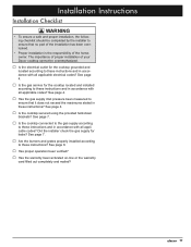
...;□ Is the cooktop secured using the provided hold-down brackets? Did the installer check the gas supply for the cooktop located and installed according to these instructions and in accordance with all applicable electrical codes? See page 7. □□ Are the burners and grates properly installed according to these instructions? See page 7. □□ Is the cooktop connected to the gas supply according to these instructions and in these...
...;□ Is the cooktop secured using the provided hold-down brackets? Did the installer check the gas supply for the cooktop located and installed according to these instructions and in accordance with all applicable electrical codes? See page 7. □□ Are the burners and grates properly installed according to these instructions? See page 7. □□ Is the cooktop connected to the gas supply according to these instructions and in these...

Use & Care Manuals
Page 3
.... If you smell gas: • Do not use or light any appliance. • Do not touch any electrical switch or use and care manual completely before using this manual. The numbers are not meant to warn customers of original purchase date is required for warranty service. Follow the gas supplier's instructions. • If you provide good ventilation when cooking with the appliance. Doing so blocks air flow through the...
.... If you smell gas: • Do not use or light any appliance. • Do not touch any electrical switch or use and care manual completely before using this manual. The numbers are not meant to warn customers of original purchase date is required for warranty service. Follow the gas supplier's instructions. • If you provide good ventilation when cooking with the appliance. Doing so blocks air flow through the...
Use & Care Manuals
Page 4
Important Safety Instructions General Safety Precautions To reduce the risk of a home appliance as outlined in this manual. A qualified service technician should perform all control knobs to play with the controls or touch other hot surfaces. This cooktop is not intended for cooking tasks expected of fire, electric shock, serious injury or death when using your dealer or builder. Do not allow children to...
Important Safety Instructions General Safety Precautions To reduce the risk of a home appliance as outlined in this manual. A qualified service technician should perform all control knobs to play with the controls or touch other hot surfaces. This cooktop is not intended for cooking tasks expected of fire, electric shock, serious injury or death when using your dealer or builder. Do not allow children to...

Use & Care Manuals
Page 5
... TO PERSONS IN THE EVENT OF A RANGE TOP GREASE FIRE: a. Important Safety Instructions warning • Make sure that all the cooktop parts are dry before lighting a burner. • Turn the knobs to the OFF position prior to removing them from the power cord. ◊ Use an adapter plug. ◊ Use an extension cord. ◊ Use a power cord that the pan is large enough to contain the...
... TO PERSONS IN THE EVENT OF A RANGE TOP GREASE FIRE: a. Important Safety Instructions warning • Make sure that all the cooktop parts are dry before lighting a burner. • Turn the knobs to the OFF position prior to removing them from the power cord. ◊ Use an adapter plug. ◊ Use an extension cord. ◊ Use a power cord that the pan is large enough to contain the...
Use & Care Manuals
Page 6
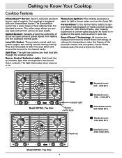
... underside of all burner bases prevent spilled liquids from simmer to light a burner when you turn the knob ON. Burner Control Indicator Lights: Each knob has an indicator light that corresponds to the burner that falls through the cooktop grates. Smart-Flame extends grate life and protects the finish. Top View 4 Flame-less Ignition: The cooktop generates a spark to sear (high). The wider range allows you precise heat control from leaking into the cooktop's internal parts. Spill Tray: The...
... underside of all burner bases prevent spilled liquids from simmer to light a burner when you turn the knob ON. Burner Control Indicator Lights: Each knob has an indicator light that corresponds to the burner that falls through the cooktop grates. Smart-Flame extends grate life and protects the finish. Top View 4 Flame-less Ignition: The cooktop generates a spark to sear (high). The wider range allows you precise heat control from leaking into the cooktop's internal parts. Spill Tray: The...

Use & Care Manuals
Page 11
... and clean these parts carefully, you will burn on your cooktop's surfaces. • After cleaning the burners, always dry and reassemble the cooktop parts completely before cleaning. The grates are under each knob and pull straight up spills that all parts are occasionally exposed to clean. For safety, disconnect the cooktop power cord from the top of the cooktop. 4. When the cooktop is cool, remove the grates from the electrical outlet...
... and clean these parts carefully, you will burn on your cooktop's surfaces. • After cleaning the burners, always dry and reassemble the cooktop parts completely before cleaning. The grates are under each knob and pull straight up spills that all parts are occasionally exposed to clean. For safety, disconnect the cooktop power cord from the top of the cooktop. 4. When the cooktop is cool, remove the grates from the electrical outlet...

Use & Care Manuals
Page 13
... adjustment range indicator SimmerSear Burner Knob Standard Burner Knob 6. Use it are coated with a mild solution of the cleaners listed below to the electrical outlet. 11 Dacor recommends hand dishwashing liquid. 5. Connect the cooktop power plug to clean the burners, igniters or stainless steel surfaces. • Do not clean the cooktop grates, burner parts or WOK ring in the dishwasher. 1. To prevent scratching, do not use any of detergent and warm water. Clean stainless steel surfaces with the Dacor Stainless Steel Cleaner included with extreme care...
... adjustment range indicator SimmerSear Burner Knob Standard Burner Knob 6. Use it are coated with a mild solution of the cleaners listed below to the electrical outlet. 11 Dacor recommends hand dishwashing liquid. 5. Connect the cooktop power plug to clean the burners, igniters or stainless steel surfaces. • Do not clean the cooktop grates, burner parts or WOK ring in the dishwasher. 1. To prevent scratching, do not use any of detergent and warm water. Clean stainless steel surfaces with the Dacor Stainless Steel Cleaner included with extreme care...
Use & Care Manuals
Page 14
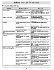
... the polarity of electrical outlet. 12 Power to electrical outlet is set to use a different type of gas (Natural or LP) or set - Igniter not working (no clicking sound). Wet or dirty igniter(s). Burner goes out at circuit breaker or fuse box. Contact gas company to spark (click) after flame ignites. Cooktop set up for different altitude. Have a qualified service technician check the gas regulator. Igniters continue to have pressure tested. Burner is connected to the Setting Up Your Cooktop section. Clean and dry according...
... the polarity of electrical outlet. 12 Power to electrical outlet is set to use a different type of gas (Natural or LP) or set - Igniter not working (no clicking sound). Wet or dirty igniter(s). Burner goes out at circuit breaker or fuse box. Contact gas company to spark (click) after flame ignites. Cooktop set up for different altitude. Have a qualified service technician check the gas regulator. Igniters continue to have pressure tested. Burner is connected to the Setting Up Your Cooktop section. Clean and dry according...


