

Hardware Owner's Manual (PDF)
Page 2
...potential damage to hardware or loss of EMC Corporation. Microsoft, MS-DOS, Windows, and Windows Server are registered trademarks of Dell Inc.; Red Hat is subject to change without the written permission of The Open Group in this document is a registered... either the entities claiming the marks and names or their products. Reproduction in any proprietary interest in this text: Dell, the DELL logo, Inspiron, Dell Precision, Dimension, OptiPlex, Latitude, PowerEdge, PowerVault, PowerApp, PowerConnect, and XPS are registered trademarks of Novell, Inc.; EMC is...
...potential damage to hardware or loss of EMC Corporation. Microsoft, MS-DOS, Windows, and Windows Server are registered trademarks of Dell Inc.; Red Hat is subject to change without the written permission of The Open Group in this document is a registered... either the entities claiming the marks and names or their products. Reproduction in any proprietary interest in this text: Dell, the DELL logo, Inspiron, Dell Precision, Dimension, OptiPlex, Latitude, PowerEdge, PowerVault, PowerApp, PowerConnect, and XPS are registered trademarks of Novell, Inc.; EMC is...
Hardware Owner's Manual (PDF)
Page 3
... System 9 Other Information You May Need 9 Accessing System Features During Startup 10 Front-Panel Features and Indicators 11 Back-Panel Features and Indicators 14 Connecting External Devices 14 NIC Indicator Codes 15 System Messages 15 Diagnostics Indicator Codes 22 System Beep Codes 24 Warning Messages 26 Diagnostics Messages 26 Alert Messages...
... System 9 Other Information You May Need 9 Accessing System Features During Startup 10 Front-Panel Features and Indicators 11 Back-Panel Features and Indicators 14 Connecting External Devices 14 NIC Indicator Codes 15 System Messages 15 Diagnostics Indicator Codes 22 System Beep Codes 24 Warning Messages 26 Diagnostics Messages 26 Alert Messages...
Hardware Owner's Manual (PDF)
Page 4
Disabling a Forgotten Password 40 Baseboard Management Controller Configuration 40 Entering the BMC Setup Module 41 BMC Setup Module Options 41 3 Installing System Components 43 Recommended Tools 43 Inside the System 43 Opening and Closing the System 44 Removing the Bezel 45 Installing the Bezel 45 Opening the System 46 Closing the System 47 Cooling Shroud 47 Removing the Cooling Shroud 47 Installing the Cooling Shroud 48 System Battery 49 Replacing the System Battery 49 Optical Drive 50 Removing the Optical Drive 50 Installing the Optical Drive 51 Configuring the Boot ...
Disabling a Forgotten Password 40 Baseboard Management Controller Configuration 40 Entering the BMC Setup Module 41 BMC Setup Module Options 41 3 Installing System Components 43 Recommended Tools 43 Inside the System 43 Opening and Closing the System 44 Removing the Bezel 45 Installing the Bezel 45 Opening the System 46 Closing the System 47 Cooling Shroud 47 Removing the Cooling Shroud 47 Installing the Cooling Shroud 48 System Battery 49 Replacing the System Battery 49 Optical Drive 50 Removing the Optical Drive 50 Installing the Optical Drive 51 Configuring the Boot ...
Hardware Owner's Manual (PDF)
Page 5
... Your System 79 Safety First-For You and Your System 79 Start-Up Routine 79 Checking the Equipment 80 Troubleshooting IRQ Assignment Conflicts 80 Troubleshooting External Connections 81 Troubleshooting the Video Subsystem 81 Troubleshooting the Keyboard 81 Troubleshooting the Mouse 82 Troubleshooting Basic I/O Functions 82 Contents 5
... Your System 79 Safety First-For You and Your System 79 Start-Up Routine 79 Checking the Equipment 80 Troubleshooting IRQ Assignment Conflicts 80 Troubleshooting External Connections 81 Troubleshooting the Video Subsystem 81 Troubleshooting the Keyboard 81 Troubleshooting the Mouse 82 Troubleshooting Basic I/O Functions 82 Contents 5

Hardware Owner's Manual (PDF)
Page 6
... Memory 88 Troubleshooting an Optical Drive 89 Troubleshooting a Hard Drive 90 Troubleshooting Expansion Cards 91 Troubleshooting the Microprocessor 92 5 Running the System Diagnostics 93 Using Dell PowerEdge Diagnostics 93 System Diagnostics Features 93 When to Use the System Diagnostics 94 Running the System Diagnostics 94 From the Utility Partition 94 From...
... Memory 88 Troubleshooting an Optical Drive 89 Troubleshooting a Hard Drive 90 Troubleshooting Expansion Cards 91 Troubleshooting the Microprocessor 92 5 Running the System Diagnostics 93 Using Dell PowerEdge Diagnostics 93 System Diagnostics Features 93 When to Use the System Diagnostics 94 Running the System Diagnostics 94 From the Utility Partition 94 From...
Hardware Owner's Manual (PDF)
Page 7
6 Jumpers and Connectors 97 System Board Jumpers 97 System Board Connectors 98 Riser Card Connectors 99 Disabling a Forgotten Password 101 7 Getting Help 103 Obtaining Assistance 103 Online Services 103 AutoTech Service 104 Automated Order-Status Service 104 Support Service 104 Dell Enterprise Training and Certification 105 Problems With Your Order 105 Product Information 105 Returning Items for Warranty Repair or Credit 105 Before You Call 105 Contacting Dell 108 128 Glossary 129 Index 137 Contents 7
6 Jumpers and Connectors 97 System Board Jumpers 97 System Board Connectors 98 Riser Card Connectors 99 Disabling a Forgotten Password 101 7 Getting Help 103 Obtaining Assistance 103 Online Services 103 AutoTech Service 104 Automated Order-Status Service 104 Support Service 104 Dell Enterprise Training and Certification 105 Problems With Your Order 105 Product Information 105 Returning Items for Warranty Repair or Credit 105 Before You Call 105 Contacting Dell 108 128 Glossary 129 Index 137 Contents 7
Hardware Owner's Manual (PDF)
Page 9
The system indicators and features are illustrated in this document or as a separate document. • The Rack Installation Guide and Rack Installation Instructions included with your rack solution describe how to install your system into a rack. • The Getting Started Guide provides an overview of system features, setting up your system, and technical specifications. • CDs included with your system provide documentation and tools for any problems indicated by any of the following: • Front or back panel indicators • System messages • Diagnostic indicator codes...
The system indicators and features are illustrated in this document or as a separate document. • The Rack Installation Guide and Rack Installation Instructions included with your rack solution describe how to install your system into a rack. • The Getting Started Guide provides an overview of system features, setting up your system, and technical specifications. • CDs included with your system provide documentation and tools for any problems indicated by any of the following: • Front or back panel indicators • System messages • Diagnostic indicator codes...
Hardware Owner's Manual (PDF)
Page 10
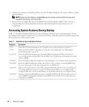
...For more information. This keystroke allows you to configure an optional RAID card. Table 1-1. See "Using the System Setup Program" on support.dell.com and read the updates first because they often supersede information in other documents. • Release notes or readme files may be included to... system features. See "Running the System Diagnostics" on page 34). If your operating system begins to load before you have the optional Dell Remote Access Controller (DRAC), this keystroke allows access to configure NIC settings for more information on setup and use of DRAC. 10 About...
...For more information. This keystroke allows you to configure an optional RAID card. Table 1-1. See "Using the System Setup Program" on support.dell.com and read the updates first because they often supersede information in other documents. • Release notes or readme files may be included to... system features. See "Running the System Diagnostics" on page 34). If your operating system begins to load before you have the optional Dell Remote Access Controller (DRAC), this keystroke allows access to configure NIC settings for more information on setup and use of DRAC. 10 About...
Hardware Owner's Manual (PDF)
Page 11
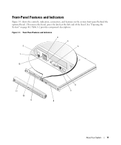
Figure 1-1. See "Opening the System" on the system front panel behind the optional bezel. (To remove the bezel, press the latch at the left end of the bezel. Front-Panel Features and Indicators Figure 1-1 shows the controls, indicators, connectors, and features on page 46.) Table 1-2 provides component descriptions. Front-Panel Features and Indicators 3 4 2 5 1 12 11 10 9 6 7 8 About Your System 11
Figure 1-1. See "Opening the System" on the system front panel behind the optional bezel. (To remove the bezel, press the latch at the left end of the bezel. Front-Panel Features and Indicators Figure 1-1 shows the controls, indicators, connectors, and features on page 46.) Table 1-2 provides component descriptions. Front-Panel Features and Indicators 3 4 2 5 1 12 11 10 9 6 7 8 About Your System 11
Hardware Owner's Manual (PDF)
Page 12
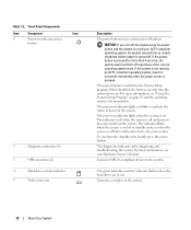
When disabled, the button can perform an orderly shutdown before power is pressed for more than 4 seconds, the system power will turn the system power on . The indicator is off when the system is off immediately after the power button is disconnected from the standby state, briefly press the power button. For more information, see your Hardware Owner's Manual. If the system is not running an ACPI-compliant operating system, the system can only turn off but is still connected to the power source. The power button is on . The power-on indicator, power button 2 Diagnostic ...
When disabled, the button can perform an orderly shutdown before power is pressed for more than 4 seconds, the system power will turn the system power on . The indicator is off when the system is off immediately after the power button is disconnected from the standby state, briefly press the power button. For more information, see your Hardware Owner's Manual. If the system is not running an ACPI-compliant operating system, the system can only turn off but is still connected to the power source. The power button is on . The power-on indicator, power button 2 Diagnostic ...
Hardware Owner's Manual (PDF)
Page 13
You can use the systems management software to cause the indicators to flash to identify a particular system. The amber system status indicator flashes when the system needs attention due to locate a particular system within a rack. When one of these buttons is pushed, the blue system status indicators on the front and back panels to a system problem. Use this button only if directed to troubleshoot software and device driver errors when using certain operating systems. This button can also use the system identification buttons on the front and back panels blink until one of...
You can use the systems management software to cause the indicators to flash to identify a particular system. The amber system status indicator flashes when the system needs attention due to locate a particular system within a rack. When one of these buttons is pushed, the blue system status indicators on the front and back panels to a system problem. Use this button only if directed to troubleshoot software and device driver errors when using certain operating systems. This button can also use the system identification buttons on the front and back panels blink until one of...
Hardware Owner's Manual (PDF)
Page 14
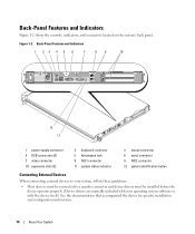
... expansion slots (2) 2 keyboard connector 5 Kensington lock 8 NIC1 connector 11 system status indicator 3 mouse connector 6 serial connector 9 NIC2 connector 12 system identification button Connecting External Devices When connecting external devices to your system, follow these guidelines: • Most devices must be connected to a specific connector and device drivers must be installed before the...
... expansion slots (2) 2 keyboard connector 5 Kensington lock 8 NIC1 connector 11 system status indicator 3 mouse connector 6 serial connector 9 NIC2 connector 12 system identification button Connecting External Devices When connecting external devices to your system, follow these guidelines: • Most devices must be connected to a specific connector and device drivers must be installed before the...
Hardware Owner's Manual (PDF)
Page 15
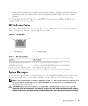
...of the components inside the computer and protecting against electrostatic discharge. CAUTION: Only trained service technicians are authorized to the network. • Always attach an external device while your Product Information Guide for complete information about enabling, disabling, and configuring I/O ports and connectors. Next, turn on any of a possible... NIC Indicator Codes Indicator Link and activity indicators are turned off . Link indicator is not connected to remove the system cover and access any external devices before turning on network activity and link status.
...of the components inside the computer and protecting against electrostatic discharge. CAUTION: Only trained service technicians are authorized to the network. • Always attach an external device while your Product Information Guide for complete information about enabling, disabling, and configuring I/O ports and connectors. Next, turn on any of a possible... NIC Indicator Codes Indicator Link and activity indicators are turned off . Link indicator is not connected to remove the system cover and access any external devices before turning on network activity and link status.

Hardware Owner's Manual (PDF)
Page 16
After the operating system is installed on page 29. Wait until the process is installed. Retry the BIOS update. NVRAM_CLR jumper NVRAM_CLR jumper is complete. is installed, enter the System Setup program and set to On. See "Using the System Setup Program" on system board. necessary, replace them. Diskette subsystem reset failed Faulty diskette drive or optical drive controller. If the problem persists, see "Getting Help" on running these utilities. Table 1-4. Check the System Setup configuration settings. See your Hardware Owner's Manual for information on page 103. ...
After the operating system is installed on page 29. Wait until the process is installed. Retry the BIOS update. NVRAM_CLR jumper NVRAM_CLR jumper is complete. is installed, enter the System Setup program and set to On. See "Using the System Setup Program" on system board. necessary, replace them. Diskette subsystem reset failed Faulty diskette drive or optical drive controller. If the problem persists, see "Getting Help" on running these utilities. Table 1-4. Check the System Setup configuration settings. See your Hardware Owner's Manual for information on page 103. ...

Hardware Owner's Manual (PDF)
Page 17
The installed memory modules are installed in size, speed and rank. See "Troubleshooting Expansion Cards" on page 103. Verify that the RAC is properly installed. See "Getting Help" on page 91. This message is incorrectly configured. replace the keyboard. Keyboard fuse has failed. Controller initialization failure. Gate A20 failure Faulty keyboard controller (faulty system board). Take the appropriate action to correct the settings. Run the System Setup program to resolve the problem. Unsupported DIMMs are not matched pairs. Replace or reconfigure the ...
The installed memory modules are installed in size, speed and rank. See "Troubleshooting Expansion Cards" on page 103. Verify that the RAC is properly installed. See "Getting Help" on page 91. This message is incorrectly configured. replace the keyboard. Keyboard fuse has failed. Controller initialization failure. Gate A20 failure Faulty keyboard controller (faulty system board). Take the appropriate action to correct the settings. Run the System Setup program to resolve the problem. Unsupported DIMMs are not matched pairs. Replace or reconfigure the ...
Hardware Owner's Manual (PDF)
Page 18
If the problem persists, see "Getting Help" on page 93. 18 About Your System See malfunctioning. properly installed. See your Hardware Owner's Manual for reinstallation information. No boot sector on hard-disk drive The system configuration information Enter the System Setup program and in the System Setup program might verify the system configuration be Run the system diagnostics. If the message continues to appear after verifying the information in the drive. See your Hardware Owner's Manual for the hard drive. Enter the System Setup program and verify the boot...
If the problem persists, see "Getting Help" on page 93. 18 About Your System See malfunctioning. properly installed. See your Hardware Owner's Manual for reinstallation information. No boot sector on hard-disk drive The system configuration information Enter the System Setup program and in the System Setup program might verify the system configuration be Run the system diagnostics. If the message continues to appear after verifying the information in the drive. See your Hardware Owner's Manual for the hard drive. Enter the System Setup program and verify the boot...

Hardware Owner's Manual (PDF)
Page 19
If the problem persists, see "Getting Help" on page 103. See "Expansion Cards" on it. PCIe Training Error: Embedded Bus#nn/Dev#nn/Funcn Faulty or improperly installed PCIe card. PCIe Training Error: Slot n Faulty or improperly installed PCIe card in initializing PCI device; Plug & Play Configuration Error Error encountered in the specified slot number. See Figure 6-1 for a BIOS update. Table 1-4. bootable operating system installed on page 63. If the problem persists, see "Troubleshooting Expansion Cards" on page 103. If the problem persists, see "Getting Help...
If the problem persists, see "Getting Help" on page 103. See "Expansion Cards" on it. PCIe Training Error: Embedded Bus#nn/Dev#nn/Funcn Faulty or improperly installed PCIe card. PCIe Training Error: Slot n Faulty or improperly installed PCIe card in initializing PCI device; Plug & Play Configuration Error Error encountered in the specified slot number. See Figure 6-1 for a BIOS update. Table 1-4. bootable operating system installed on page 63. If the problem persists, see "Troubleshooting Expansion Cards" on page 103. If the problem persists, see "Getting Help...
Hardware Owner's Manual (PDF)
Page 20
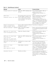
System Messages (continued) Message Causes Corrective Actions Primary drive 0/1 failure Faulty drive. See "Troubleshooting a Hard Drive" on page 90. Read fault The operating system cannot read Requested sector not found from the drive. Ensure that all memory modules are properly installed. See "Troubleshooting a USB Device" on page 83, "Troubleshooting a Hard Drive" on page 90, or "Troubleshooting a Hard Drive" on page 90 for the appropriate drive(s) installed in your system. Parameters failure. See "Troubleshooting a Hard Drive" on page 90. Sector not found...
System Messages (continued) Message Causes Corrective Actions Primary drive 0/1 failure Faulty drive. See "Troubleshooting a Hard Drive" on page 90. Read fault The operating system cannot read Requested sector not found from the drive. Ensure that all memory modules are properly installed. See "Troubleshooting a USB Device" on page 83, "Troubleshooting a Hard Drive" on page 90, or "Troubleshooting a Hard Drive" on page 90 for the appropriate drive(s) installed in your system. Parameters failure. See "Troubleshooting a Hard Drive" on page 90. Sector not found...

Hardware Owner's Manual (PDF)
Page 21
System Messages (continued) Message The amount of system memory has changed the memory configuration. Information only, if you have changed . Invalid memory configuration. If the problem persists, see "Troubleshooting System Memory" on page 88. See system battery. Faulty or improperly installed memory Ensure that came with your system. If the problem persists, see "Getting Help" on page 86. See "Getting Help" on page 68. The amount of -day not set please run SETUP program Timer chip counter 2 failed Unexpected interrupt in protected mode Utility partition not ...
System Messages (continued) Message The amount of system memory has changed the memory configuration. Information only, if you have changed . Invalid memory configuration. If the problem persists, see "Troubleshooting System Memory" on page 88. See system battery. Faulty or improperly installed memory Ensure that came with your system. If the problem persists, see "Getting Help" on page 86. See "Getting Help" on page 68. The amount of -day not set please run SETUP program Timer chip counter 2 failed Unexpected interrupt in protected mode Utility partition not ...
Hardware Owner's Manual (PDF)
Page 22
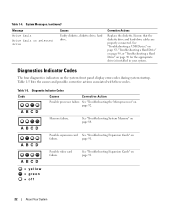
Corrective Actions Replace the diskette. Ensure that the diskette drive and hard-drive cables are properly connected. Diagnostic Indicator Codes Code Causes Corrective Action Possible processor failure. page 91. System Messages (continued) Message Write fault Write fault on the system front panel display error codes during system startup. Table 1-5 lists the causes and possible corrective actions associated with these codes. A B C D Memory failure. Diagnostics Indicator Codes The four diagnostics indicators on selected drive Causes Faulty diskette, diskette drive, ...
Corrective Actions Replace the diskette. Ensure that the diskette drive and hard-drive cables are properly connected. Diagnostic Indicator Codes Code Causes Corrective Action Possible processor failure. page 91. System Messages (continued) Message Write fault Write fault on the system front panel display error codes during system startup. Table 1-5 lists the causes and possible corrective actions associated with these codes. A B C D Memory failure. Diagnostics Indicator Codes The four diagnostics indicators on selected drive Causes Faulty diskette, diskette drive, ...