

Owners Manual
Page 7
... System Memory...137 Troubleshooting An Internal USB Key...138 Troubleshooting An SD Card...138 Troubleshooting An Optical Drive...139 Troubleshooting A Hard Drive...139 Troubleshooting Expansion Cards...140 Troubleshooting Processors...140 6 Using System Diagnostics...141 Dell Online Diagnostics...141 Dell Embedded System Diagnostics...141 When To Use The Embedded System Diagnostics 141 Running The Embedded System Diagnostics 141 System Diagnostic Controls...142 7 Jumpers And Connectors...143 System Board Jumper Settings...143 System Board Connectors...144 Disabling A Forgotten Password...
... System Memory...137 Troubleshooting An Internal USB Key...138 Troubleshooting An SD Card...138 Troubleshooting An Optical Drive...139 Troubleshooting A Hard Drive...139 Troubleshooting Expansion Cards...140 Troubleshooting Processors...140 6 Using System Diagnostics...141 Dell Online Diagnostics...141 Dell Embedded System Diagnostics...141 When To Use The Embedded System Diagnostics 141 Running The Embedded System Diagnostics 141 System Diagnostic Controls...142 7 Jumpers And Connectors...143 System Board Jumper Settings...143 System Board Connectors...144 Disabling A Forgotten Password...

Owners Manual
Page 13
... back panels can be used to insert a vFlash media card. Allows you to locate a particular system within a rack. NOTE: In systems supporting S110 Software RAID configuration, hard-drive slots 4 through 7 do so by qualified support personnel or by descriptive text. Item Indicator, Button, or Icon Description Connector 2.5 inch harddrive systems Up to thirty two 2.5 inch hotswappable hard drives. Up to four Dell PowerEdge Express Flash devices (PCIe SSDs). The power-on indicator lights...
... back panels can be used to insert a vFlash media card. Allows you to locate a particular system within a rack. NOTE: In systems supporting S110 Software RAID configuration, hard-drive slots 4 through 7 do so by qualified support personnel or by descriptive text. Item Indicator, Button, or Icon Description Connector 2.5 inch harddrive systems Up to thirty two 2.5 inch hotswappable hard drives. Up to four Dell PowerEdge Express Flash devices (PCIe SSDs). The power-on indicator lights...
Owners Manual
Page 23
... management features such as operating system deployment, hardware diagnostics, platform updates, and platform configuration, using the: • Standard graphical browser, which is enabled by the iDRAC license purchased. Once you specify the boot mode, the system boots in the specified boot mode and you to install your operating system: • BIOS boot mode (the default) is the standard BIOS-level boot interface. • UEFI boot mode is displayed in the Boot Mode field of the Boot Settings screen of System Setup. Enters...
... management features such as operating system deployment, hardware diagnostics, platform updates, and platform configuration, using the: • Standard graphical browser, which is enabled by the iDRAC license purchased. Once you specify the boot mode, the system boots in the specified boot mode and you to install your operating system: • BIOS boot mode (the default) is the standard BIOS-level boot interface. • UEFI boot mode is displayed in the Boot Mode field of the Boot Settings screen of System Setup. Enters...

Owners Manual
Page 25
... name, BIOS version, Service Tag, and so on . Serial Communication Displays options to installed memory. It also enables or disables support for System Setup change based on . Menu Item System BIOS iDRAC Settings Device Settings Description This option is used to view and configure iDRAC settings. Miscellaneous Settings Displays options to change the processor power management settings, memory frequency, and so on the system configuration. System BIOS Version Displays the BIOS version installed on . System Setup Main Screen NOTE: Press to reset the BIOS or UEFI settings to...
... name, BIOS version, Service Tag, and so on . Serial Communication Displays options to installed memory. It also enables or disables support for System Setup change based on . Menu Item System BIOS iDRAC Settings Device Settings Description This option is used to view and configure iDRAC settings. Miscellaneous Settings Displays options to change the processor power management settings, memory frequency, and so on the system configuration. System BIOS Version Displays the BIOS version installed on . System Setup Main Screen NOTE: Press to reset the BIOS or UEFI settings to...

Owners Manual
Page 29
.... By default, the User Accessible USB Ports option is written on the system board. By default, Internal SD Card Redundancy option is set to Mirror mode, data is set to All Ports On. If any one of PCIe cards installed in system startup. CAUTION: Slot disablement must be enabled and the port address used only when the installed peripheral card is set to the active SD card. Serial Communications Screen Menu Item Description Serial Communication Allows you to set to Disabled. BIOS console redirection...
.... By default, the User Accessible USB Ports option is written on the system board. By default, Internal SD Card Redundancy option is set to Mirror mode, data is set to All Ports On. If any one of PCIe cards installed in system startup. CAUTION: Slot disablement must be enabled and the port address used only when the installed peripheral card is set to the active SD card. Serial Communications Screen Menu Item Description Serial Communication Allows you to set to Disabled. BIOS console redirection...

Owners Manual
Page 36
... to setup and configure the iDRAC parameters using the iDRAC Settings Utility. BIOS Boot Menu Displays the list of the features on the system and their health status. Select the boot option you to access the System Setup. Adds a new boot option. Boot Manager Screen Menu Item Description Continue Normal Boot The system attempts to boot to devices starting with the first item in the boot option list. System Utilities Enables you wish to access the BIOS Update File Explorer, run the Dell Diagnostics program, and reboot the...
... to setup and configure the iDRAC parameters using the iDRAC Settings Utility. BIOS Boot Menu Displays the list of the features on the system and their health status. Select the boot option you to access the System Setup. Adds a new boot option. Boot Manager Screen Menu Item Description Continue Normal Boot The system attempts to boot to devices starting with the first item in the boot option list. System Utilities Enables you wish to access the BIOS Update File Explorer, run the Dell Diagnostics program, and reboot the...

Owners Manual
Page 55
... surface. 13. Run the system memory test in your product documentation, or as directed by the online or telephone service and support team. Remove the cables. a) For a 2.5 inch drive flex bay, remove the cables from the chassis. 5. Align the memory module's edge connector with the alignment key of the following configurations: • Sixteen 2.5 inch hard drives • Four Dell PowerEdge Express Flash devices • Four 3.5 inch hard drives Removing A Flex Bay CAUTION...
... surface. 13. Run the system memory test in your product documentation, or as directed by the online or telephone service and support team. Remove the cables. a) For a 2.5 inch drive flex bay, remove the cables from the chassis. 5. Align the memory module's edge connector with the alignment key of the following configurations: • Sixteen 2.5 inch hard drives • Four Dell PowerEdge Express Flash devices • Four 3.5 inch hard drives Removing A Flex Bay CAUTION...

Owners Manual
Page 59
... partially installed carrier's shield spring and make it . 2. Figure 22. CAUTION: When installing a hard drive, ensure that your operating system. If a hard-drive blank is not covered by a certified service technician. Read and follow the safety instructions that is not authorized by Dell is installed in the hard-drive slot, remove it unusable. Press the release button on the replacement hard drive is immediately lost after the hard drive is powered on, the hard drive automatically...
... partially installed carrier's shield spring and make it . 2. Figure 22. CAUTION: When installing a hard drive, ensure that your operating system. If a hard-drive blank is not covered by a certified service technician. Read and follow the safety instructions that is not authorized by Dell is installed in the hard-drive slot, remove it unusable. Press the release button on the replacement hard drive is immediately lost after the hard drive is powered on, the hard drive automatically...

Owners Manual
Page 65
... the safety instructions that accompanied the drive. If installed, remove the front bezel. 3. Close the system. 12. Connect the power and data cable to the backplane and the system board. NOTE: In the event of the drive. 10. Align the drive with a particular fan, the fan number is not covered by the online or telephone service and support team. Installing The Optical Drive Or Tape Drive CAUTION: Many repairs may only...
... the safety instructions that accompanied the drive. If installed, remove the front bezel. 3. Close the system. 12. Connect the power and data cable to the backplane and the system board. NOTE: In the event of the drive. 10. Align the drive with a particular fan, the fan number is not covered by the online or telephone service and support team. Installing The Optical Drive Or Tape Drive CAUTION: Many repairs may only...

Owners Manual
Page 76
... any device drivers required for the card. Remove the PCIe card holder. Close the PCIe card latch. 11. Reconnect the system to servicing that came with the PCIe card connector. 9. You should only perform troubleshooting and simple repairs as authorized in the documentation for the card as described in your warranty. CAUTION: Do not use excessive force when removing the cables as directed by Dell is...
... any device drivers required for the card. Remove the PCIe card holder. Close the PCIe card latch. 11. Reconnect the system to servicing that came with the PCIe card connector. 9. You should only perform troubleshooting and simple repairs as authorized in the documentation for the card as described in your warranty. CAUTION: Do not use excessive force when removing the cables as directed by Dell is...
Owners Manual
Page 86
... that came with the product. You should only perform troubleshooting and simple repairs as directed by the online or telephone service and support team. For information about the cable management arm, see the iDRAC7 User's Guide at support.dell.com/manuals. Press the release latch and slide the power supply out of the load, thus operating at a time in a system that is not authorized...
... that came with the product. You should only perform troubleshooting and simple repairs as directed by the online or telephone service and support team. For information about the cable management arm, see the iDRAC7 User's Guide at support.dell.com/manuals. Press the release latch and slide the power supply out of the load, thus operating at a time in a system that is not authorized...

Owners Manual
Page 133
... step to begin troubleshooting the other USB devices, go to the monitor. 3. Troubleshooting The Video Subsystem 1. Troubleshooting System Startup Failure If you installed the operating system. Check the video interface cabling from the UEFI Boot Manager, the system hangs. Run the appropriate diagnostic test. If the problem is resolved, replace the faulty keyboard/mouse. 6. Troubleshooting A USB Device Use the following steps to the monitor. 2. Disconnect the keyboard and mouse cables from the system briefly and reconnect them. 2. Replace the keyboard/mouse with the...
... step to begin troubleshooting the other USB devices, go to the monitor. 3. Troubleshooting The Video Subsystem 1. Troubleshooting System Startup Failure If you installed the operating system. Check the video interface cabling from the UEFI Boot Manager, the system hangs. Run the appropriate diagnostic test. If the problem is resolved, replace the faulty keyboard/mouse. 6. Troubleshooting A USB Device Use the following steps to the monitor. 2. Disconnect the keyboard and mouse cables from the system briefly and reconnect them. 2. Replace the keyboard/mouse with the...

Owners Manual
Page 134
... a device causes the same problem, power down all troubleshooting fails, see Getting Help. If the link indicator does not light, check all network cables are bound. See the NIC's documentation. - See the NIC's documentation. 5. If the system is not accessible, reset the NVRAM_CLR jumper inside your product documentation, or as authorized in the System Setup options. Turn on the NIC connector: - If applicable, change the autonegotiation setting...
... a device causes the same problem, power down all troubleshooting fails, see Getting Help. If the link indicator does not light, check all network cables are bound. See the NIC's documentation. - See the NIC's documentation. 5. If the system is not accessible, reset the NVRAM_CLR jumper inside your product documentation, or as authorized in the System Setup options. Turn on the NIC connector: - If applicable, change the autonegotiation setting...

Owners Manual
Page 135
... covered by a certified service technician. USB memory key - Expansion-card risers (if present) - Expansion cards - Reinstall the components you removed. 9. If the tests fail, see Getting Help. 8. Cooling-fan assembly (if present) - Memory modules 4. Damage due to servicing that you removed in your warranty. Hard-drive carriers - Close the system. 6. Hard-drive backplane - Power supply(s) - Cooling fans - Processor(s) and heat sink(s) - Turn on the system and attached peripherals. Hard-drive backplane 4. Run the appropriate diagnostic test. Cooling-fan...
... covered by a certified service technician. USB memory key - Expansion-card risers (if present) - Expansion cards - Reinstall the components you removed. 9. If the tests fail, see Getting Help. 8. Cooling-fan assembly (if present) - Memory modules 4. Damage due to servicing that you removed in your warranty. Hard-drive carriers - Close the system. 6. Hard-drive backplane - Power supply(s) - Cooling fans - Processor(s) and heat sink(s) - Turn on the system and attached peripherals. Hard-drive backplane 4. Run the appropriate diagnostic test. Cooling-fan...

Owners Manual
Page 136
... power supply by a certified service technician. If the problem persists, see Getting Help. Damage due to servicing that is not authorized by Dell is caused by a certified service technician. If the tests fail, see Getting Help. This situation is not covered by your warranty. Enter the System Setup. NOTE: Some software may only be done by removing and reinstalling it. Troubleshooting Cooling Problems CAUTION: Many repairs...
... power supply by a certified service technician. If the problem persists, see Getting Help. Damage due to servicing that is not authorized by Dell is caused by a certified service technician. If the tests fail, see Getting Help. This situation is not covered by your warranty. Enter the System Setup. NOTE: Some software may only be done by removing and reinstalling it. Troubleshooting Cooling Problems CAUTION: Many repairs...

Owners Manual
Page 138
... Devices screen. 2. You should only perform troubleshooting and simple repairs as authorized in SD card slot 2 and proceed to Disabled, replace the failed SD card with the product. Locate the USB key and reseat it into SD card slot 2. 8. If the problem is set to avoid loss of the system. 16. If SD card 2 has failed, install a new SD card in your product documentation, or as directed by a certified service technician. Troubleshooting...
... Devices screen. 2. You should only perform troubleshooting and simple repairs as authorized in SD card slot 2 and proceed to Disabled, replace the failed SD card with the product. Locate the USB key and reseat it into SD card slot 2. 8. If the problem is set to avoid loss of the system. 16. If SD card 2 has failed, install a new SD card in your product documentation, or as directed by a certified service technician. Troubleshooting...

Owners Manual
Page 139
... Dell is properly connected to servicing that a power cable is not covered by a certified service technician. c) Take the hard drive offline and reseat the drive. See the operating system documentation for your warranty. Damage due to the drive. 9. Remove the front bezel. 7. Run the appropriate diagnostic test. d) Exit the configuration utility and allow the system to boot to its electrical outlet and turn the system on the hard drive. Troubleshooting An Optical Drive CAUTION: Many repairs...
... Dell is properly connected to servicing that a power cable is not covered by a certified service technician. c) Take the hard drive offline and reseat the drive. See the operating system documentation for your warranty. Damage due to the drive. 9. Remove the front bezel. 7. Run the appropriate diagnostic test. d) Exit the configuration utility and allow the system to boot to its electrical outlet and turn the system on the hard drive. Troubleshooting An Optical Drive CAUTION: Many repairs...

Technical Guide
Page 7
...; processor E5-2600 product family 2 2 x Intel QuickPath Interconnect (QPI) links: 6.4 GT/s, 7.2 GT/s, 8.0 GT/s 2.5MB per core; Table 2 summarizes the specifications for each of multiple smaller or previous-generation servers. For the latest information on supported features, visit Dell.com. In comparison, the Dell PowerEdge T620 offers more disk drive options, more PCIe slots, PCIe 3.0, Express Flash PCIe solid-state drives, a larger memory footprint, and optional internal graphics...
...; processor E5-2600 product family 2 2 x Intel QuickPath Interconnect (QPI) links: 6.4 GT/s, 7.2 GT/s, 8.0 GT/s 2.5MB per core; Table 2 summarizes the specifications for each of multiple smaller or previous-generation servers. For the latest information on supported features, visit Dell.com. In comparison, the Dell PowerEdge T620 offers more disk drive options, more PCIe slots, PCIe 3.0, Express Flash PCIe solid-state drives, a larger memory footprint, and optional internal graphics...
Technical Guide
Page 41
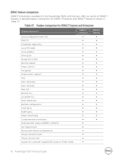
...) Part replacement Backup and restore configurations Virtual console (4 user) Virtual console chat Support for customer-supplied SD cards for vFlash media iDRAC7 Enterprise iDRAC7 Express A detailed feature comparison for the PowerEdge T620, and Dell also offers an option of iDRAC7 Express. Feature (function) Local configuration with USC IPMI 2.0 Embedded diagnostics Local OS install Local updates Driver pack Shared NIC (LOM) Remote update Power control Encryption Crash screen capture1 IPv6 Auto-discovery Auto-recovery...
...) Part replacement Backup and restore configurations Virtual console (4 user) Virtual console chat Support for customer-supplied SD cards for vFlash media iDRAC7 Enterprise iDRAC7 Express A detailed feature comparison for the PowerEdge T620, and Dell also offers an option of iDRAC7 Express. Feature (function) Local configuration with USC IPMI 2.0 Embedded diagnostics Local OS install Local updates Driver pack Shared NIC (LOM) Remote update Power control Encryption Crash screen capture1 IPv6 Auto-discovery Auto-recovery...
Technical Guide
Page 52
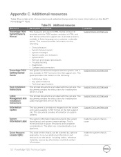
.... This code on the following : Initial setup steps Key system features Technical specifications This printed document is provided with the system, and is minimized due to access additional information and resources for installing the cable management arm on the Dell support site. The document provides the instructions for the server, including videos, reference materials, service tag information, and Dell contact information. This manual provides...
.... This code on the following : Initial setup steps Key system features Technical specifications This printed document is provided with the system, and is minimized due to access additional information and resources for installing the cable management arm on the Dell support site. The document provides the instructions for the server, including videos, reference materials, service tag information, and Dell contact information. This manual provides...


