Owners Manual
Page 3
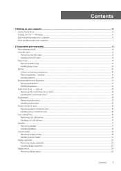
......8 microSD card...8 Removing microSD card...8 Installing microSD card...8 Base cover...8 Removing base cover...8 Installing base cover...10 Battery...10 Lithium-ion battery precautions...10 Removing battery - optional ...13 Removing M.2 Solid State Drive (SSD)...13 Installing M.2 Solid State Drive ...14 Audio board...14...connector port...15 Removing power connector port...15 Installing power connector port...16 Coin-cell battery...16 Removing coin cell battery...16 Installing coin cell battery...17 Speaker...17 Removing speaker...17 Installing speakers...18 System board...19 Removing system ...
......8 microSD card...8 Removing microSD card...8 Installing microSD card...8 Base cover...8 Removing base cover...8 Installing base cover...10 Battery...10 Lithium-ion battery precautions...10 Removing battery - optional ...13 Removing M.2 Solid State Drive (SSD)...13 Installing M.2 Solid State Drive ...14 Audio board...14...connector port...15 Removing power connector port...15 Installing power connector port...16 Coin-cell battery...16 Removing coin cell battery...16 Installing coin cell battery...17 Speaker...17 Removing speaker...17 Installing speakers...18 System board...19 Removing system ...
Owners Manual
Page 5
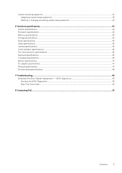
ePSA diagnostics 49 Running the ePSA Diagnostics...49 Real Time Clock reset...49 8 Contacting Dell...51 Contents 5 System and setup password...42 Assigning a system setup password...43 Deleting or changing an existing system setup ...specifications...45 Camera specifications...45 Communication specifications...46 Port and connector specifications...46 Keyboard specifications...46 Touchpad specifications...46 Battery specifications...47 AC adapter specifications...47 Physical specifications...47 Environmental specifications...48 7 Troubleshooting...49 Enhanced Pre-Boot System Assessment -
ePSA diagnostics 49 Running the ePSA Diagnostics...49 Real Time Clock reset...49 8 Contacting Dell...51 Contents 5 System and setup password...42 Assigning a system setup password...43 Deleting or changing an existing system setup ...specifications...45 Camera specifications...45 Communication specifications...46 Port and connector specifications...46 Keyboard specifications...46 Touchpad specifications...46 Battery specifications...47 AC adapter specifications...47 Physical specifications...47 Environmental specifications...48 7 Troubleshooting...49 Enhanced Pre-Boot System Assessment -

Owners Manual
Page 7
... Step # 8. Disconnect your computer After you complete any replacement procedure, ensure that you connect any telephone or network cables to the computer, use batteries designed for this particular Dell computer. After working inside your computer and all attached devices from their electrical outlets. 4. Connect any external devices, such as a port replicator or...
... Step # 8. Disconnect your computer After you complete any replacement procedure, ensure that you connect any telephone or network cables to the computer, use batteries designed for this particular Dell computer. After working inside your computer and all attached devices from their electrical outlets. 4. Connect any external devices, such as a port replicator or...

Owners Manual
Page 10
... to secure the base cover to the computer [3]. microSD card b. c. In such an instance, contact Dell technical support for assistance and further instructions. • If the battery gets stuck inside your computer as a result of the cover until it from the connector on or against... your computer. Remove the M2.0x3.0 screws that secure the battery to the computer. 4. Follow the procedure in the base cover front edge into place. 3. Lift the battery away from https://www.dell.com or authorized Dell partners and resellers. Toe in After working inside your computer....
... to secure the base cover to the computer [3]. microSD card b. c. In such an instance, contact Dell technical support for assistance and further instructions. • If the battery gets stuck inside your computer as a result of the cover until it from the connector on or against... your computer. Remove the M2.0x3.0 screws that secure the battery to the computer. 4. Follow the procedure in the base cover front edge into place. 3. Lift the battery away from https://www.dell.com or authorized Dell partners and resellers. Toe in After working inside your computer....
Owners Manual
Page 11
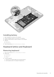
... system board [1]. Follow the procedure in Before working inside your computer. Remove the: a. b. Installing battery 1. Insert the battery into the slot on the battery. 3. Connect the battery cable to the release the keyboard [2]. Replace the M2x3 screws to secure the battery to the computer. 4. Follow the procedure in After working inside your computer. 2. Disassembly and...
... system board [1]. Follow the procedure in Before working inside your computer. Remove the: a. b. Installing battery 1. Insert the battery into the slot on the battery. 3. Connect the battery cable to the release the keyboard [2]. Replace the M2x3 screws to secure the battery to the computer. 4. Follow the procedure in After working inside your computer. 2. Disassembly and...
Owners Manual
Page 13
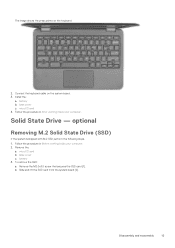
base cover c. battery b. optional Removing M.2 Solid State Drive (SSD) If the system is shipped with M.2 SSD perform the following steps. 1. microSD card b. To remove the SSD: a. Remove the ... system board. 3. Connect the keyboard cable on the keyboard. 2. base cover c. Solid State Drive - Remove the: a. Follow the procedure in After working inside your computer. 2. battery 3. Slide and lift the SSD card from the system board [2]. Install the: a. microSD card 4.
base cover c. battery b. optional Removing M.2 Solid State Drive (SSD) If the system is shipped with M.2 SSD perform the following steps. 1. microSD card b. To remove the SSD: a. Remove the ... system board. 3. Connect the keyboard cable on the keyboard. 2. base cover c. Solid State Drive - Remove the: a. Follow the procedure in After working inside your computer. 2. battery 3. Slide and lift the SSD card from the system board [2]. Install the: a. microSD card 4.
Owners Manual
Page 14
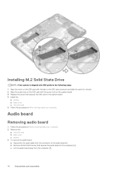
... screw that secures the audio board on the SSD card with SSD perform the following steps. 1. Follow the procedure in After working inside your computer. 2. battery 3. Disconnect the audio cable from the computer [3]. 14 Disassembly and reassembly Align the notch on the computer [2]. base cover c. Remove the M.2.0x3.0 screw that secures... screw hole on the SSD card with the screw hole on the audio board [1]. microSD card 5. Install the: a. Remove the: a. To remove the audio board: a. battery b. Follow the procedure in Before working inside your computer.
... screw that secures the audio board on the SSD card with SSD perform the following steps. 1. Follow the procedure in After working inside your computer. 2. battery 3. Disconnect the audio cable from the computer [3]. 14 Disassembly and reassembly Align the notch on the computer [2]. base cover c. Remove the M.2.0x3.0 screw that secures... screw hole on the SSD card with the screw hole on the audio board [1]. microSD card 5. Install the: a. Remove the: a. To remove the audio board: a. battery b. Follow the procedure in Before working inside your computer.
Owners Manual
Page 15
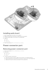
Insert the audio board into the slot on the computer [2]. battery b. Power connector port Removing power connector port 1. Remove the: a. microSD card 5. b. base cover c. To remove the power connector port: a. Disassembly and reassembly ...the procedure in Before working inside your computer. Connect the audio cable to the computer. 3. Follow the procedure in After working inside your computer. 2. battery 3. Slide and lift the power connector port away from the connector on the audio board. 4. Installing audio board 1. Replace the M2x3 screw that secure...
Insert the audio board into the slot on the computer [2]. battery b. Power connector port Removing power connector port 1. Remove the: a. microSD card 5. b. base cover c. To remove the power connector port: a. Disassembly and reassembly ...the procedure in Before working inside your computer. Connect the audio cable to the computer. 3. Follow the procedure in After working inside your computer. 2. battery 3. Slide and lift the power connector port away from the connector on the audio board. 4. Installing audio board 1. Replace the M2x3 screw that secure...
Owners Manual
Page 16
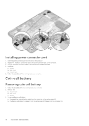
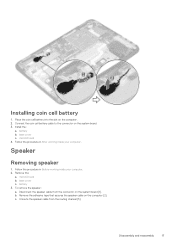
... the connector on the computer. 2. microSD card 5. Follow the procedure in Before working inside your computer. Remove the: a. battery 3. Installing power connector port 1. Insert the power connector port into the slot on the system board [1]. Install the: a. Disconnect the coin... cell battery cable from the computer [2]. 16 Disassembly and reassembly Pry the coin cell battery to the connector on the system board. 4. Follow the procedure in After working inside your computer. 2....
... the connector on the computer. 2. microSD card 5. Follow the procedure in Before working inside your computer. Remove the: a. battery 3. Installing power connector port 1. Insert the power connector port into the slot on the system board [1]. Install the: a. Disconnect the coin... cell battery cable from the computer [2]. 16 Disassembly and reassembly Pry the coin cell battery to the connector on the system board. 4. Follow the procedure in After working inside your computer. 2....
Owners Manual
Page 17
... reassembly 17 Install the: a. battery b. Remove the adhesive tape that secures the speaker cable on the computer. 2. c. Speaker Removing speaker 1. To remove the speaker: a. Unroute the speaker cable from the ... on the system board. 3. Follow the procedure in After working inside your computer. 2. Disconnect the speaker cable from the routing channel [3]. Place the coin cell battery into the slot on the computer [2]. Follow the procedure in Before working inside your computer. base cover c. Connect the coin cell...
... reassembly 17 Install the: a. battery b. Remove the adhesive tape that secures the speaker cable on the computer. 2. c. Speaker Removing speaker 1. To remove the speaker: a. Unroute the speaker cable from the ... on the system board. 3. Follow the procedure in After working inside your computer. 2. Disconnect the speaker cable from the routing channel [3]. Place the coin cell battery into the slot on the computer [2]. Follow the procedure in Before working inside your computer. base cover c. Connect the coin cell...

Owners Manual
Page 19
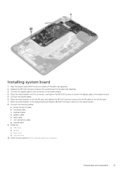
... cable [1] b. b. Remove the M2.0xM3.0 screws and lift the metal bracket that secure on the system board [4, 5]. Remove the: a. Disassembly and reassembly 19 Install the: a. battery b. System board Removing system board 1. Follow the procedure in After working inside your computer. 2. Disconnect the following cables: a. To disconnect the cable: a. Disconnect coin cell...
... cable [1] b. b. Remove the M2.0xM3.0 screws and lift the metal bracket that secure on the system board [4, 5]. Remove the: a. Disassembly and reassembly 19 Install the: a. battery b. System board Removing system board 1. Follow the procedure in After working inside your computer. 2. Disconnect the following cables: a. To disconnect the cable: a. Disconnect coin cell...
Owners Manual
Page 21
... the connector, and tighten the M2.0x3.0 screws to secure the display cable to secure on the system board. 4. touchpad cable c. speaker cable e. coin cell battery cable g. battery c. Disassembly and reassembly 21 Connect the display cable to the palm rest assembly. 3. keyboard cable d. camera cable 9. Connect the following cables: a. SSD card b. Replace...
... the connector, and tighten the M2.0x3.0 screws to secure the display cable to secure on the system board. 4. touchpad cable c. speaker cable e. coin cell battery cable g. battery c. Disassembly and reassembly 21 Connect the display cable to the palm rest assembly. 3. keyboard cable d. camera cable 9. Connect the following cables: a. SSD card b. Replace...
Owners Manual
Page 22
battery 3. b. b. To disconnect WLAN cable: a. microSD card b. Remove the screws M2.0x3.0 and lift the metal bracket that secure the WLAN card on the system board [1, 2]. ...
battery 3. b. b. To disconnect WLAN cable: a. microSD card b. Remove the screws M2.0x3.0 and lift the metal bracket that secure the WLAN card on the system board [1, 2]. ...

Owners Manual
Page 24
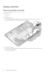
... cover c. Display bezel Removing display bezel 1. base cover c. Remove the hinge cap and the mylar cap that secures the display bezel to the display assembly. 3. battery b. Connect the WLAN cables. 7. Place the metal bracket, and tighten the M2.0x3.0 screw to the computer. 6. Place the display bezel on the system board... cable) connector, and tighten the M2.0x3.0 screws to secure the display cable to the WLAN cable on the display assembly. 2. Remove the: a. microSD card 9. battery 3. 5.
... cover c. Display bezel Removing display bezel 1. base cover c. Remove the hinge cap and the mylar cap that secures the display bezel to the display assembly. 3. battery b. Connect the WLAN cables. 7. Place the metal bracket, and tighten the M2.0x3.0 screw to the computer. 6. Place the display bezel on the system board... cable) connector, and tighten the M2.0x3.0 screws to secure the display cable to the WLAN cable on the display assembly. 2. Remove the: a. microSD card 9. battery 3. 5.

Owners Manual
Page 25
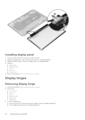
... M2.0x3.0 screws that secure the display panel to the display assembly [1] and lift to turn over the display panel to access the eDP cable [2]. 4. battery b. display assembly e. display bezel 3. Peel off the adhesive tape [1]. Disconnect the display cable from the connector on the display panel [2]. Follow the procedure in Before...
... M2.0x3.0 screws that secure the display panel to the display assembly [1] and lift to turn over the display panel to access the eDP cable [2]. 4. battery b. display assembly e. display bezel 3. Peel off the adhesive tape [1]. Disconnect the display cable from the connector on the display panel [2]. Follow the procedure in Before...
Owners Manual
Page 26
... Follow the procedure in After working inside your computer. 2. display bezel f. Replace the display panel to the display assembly [1]. display bezel b. battery d. base cover e. Remove the: a. Install the: a. display assembly e. Replace the M2x3 screws to secure the display panel to the connector,... and affix the tape. 2. display panel 3. To remove display hinge: a. battery d. Connect the eDP cable to the display assembly. 4. Follow the procedure in Before working inside your computer Display hinges Removing display hinge 1. ...
... Follow the procedure in After working inside your computer. 2. display bezel f. Replace the display panel to the display assembly [1]. display bezel b. battery d. base cover e. Remove the: a. Install the: a. display assembly e. Replace the M2x3 screws to secure the display panel to the connector,... and affix the tape. 2. display panel 3. To remove display hinge: a. battery d. Connect the eDP cable to the display assembly. 4. Follow the procedure in Before working inside your computer Display hinges Removing display hinge 1. ...
Owners Manual
Page 27
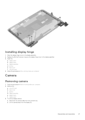
... Disassembly and reassembly 27 display bezel c. base cover c. display panel 3. To remove display camera: a. b. display panel b. battery e. microSD card b. Lift the camera away from the connector [1]. Follow the procedure in After working inside your computer. 2. display bezel f. ...display assembly d. battery d. Disconnect the camera cable from the display [2]. Installing display hinge 1. microSD card 4. display assembly e. Replace the...
... Disassembly and reassembly 27 display bezel c. base cover c. display panel 3. To remove display camera: a. b. display panel b. battery e. microSD card b. Lift the camera away from the connector [1]. Follow the procedure in After working inside your computer. 2. display bezel f. ...display assembly d. battery d. Disconnect the camera cable from the display [2]. Installing display hinge 1. microSD card 4. display assembly e. Replace the...

Owners Manual
Page 28
Installing camera 1. display panel b. base cover f. Follow the procedure in After working inside your computer 28 Disassembly and reassembly Install the: a. microSD card 4. Connect the camera cable to the connector on the display assembly. 2. display bezel c. Place the camera on the display assembly. 3. display assembly d. battery e.
Installing camera 1. display panel b. base cover f. Follow the procedure in After working inside your computer 28 Disassembly and reassembly Install the: a. microSD card 4. Connect the camera cable to the connector on the display assembly. 2. display bezel c. Place the camera on the display assembly. 3. display assembly d. battery e.
Owners Manual
Page 36
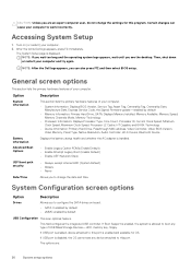
... appears, press F2 immediately. The System Setup page is an optional feature. NOTE: After the Dell logo appears, you can cause your computer to configure the SATA drives on (or restart) your computer. • System Information: Displays BIOS Version...MAC address, Video Controller, Video BIOS Version, Video Memory, Panel Type, Native Resolution, Audio Controller, Wi-Fi Device, Bluetooth Device Battery Information Advanced Boot Options Displays the battery status health and whether the AC adapter is disabled, the OS cannot see the desktop. Then, shut down or restart your computer...
... appears, press F2 immediately. The System Setup page is an optional feature. NOTE: After the Dell logo appears, you can cause your computer to configure the SATA drives on (or restart) your computer. • System Information: Displays BIOS Version...MAC address, Video Controller, Video BIOS Version, Video Memory, Panel Type, Native Resolution, Audio Controller, Wi-Fi Device, Bluetooth Device Battery Information Advanced Boot Options Displays the battery status health and whether the AC adapter is disabled, the OS cannot see the desktop. Then, shut down or restart your computer...

Owners Manual
Page 37
...Default setting: Not set Strong Password Allows you to always set the display brightness depending up on the power source-On Battery and On AC. USB PowerShare Audio Debug Memory Frequency Configuration Miscellaneous Devices This field configures the USB PowerShare feature behavior. The... LCD brightness is not selected. Default Setting: Enable Strong Password is independent for battery and AC adapter. This option allows you to enforce the option to charge external devices using the slider. Default setting: ...
...Default setting: Not set Strong Password Allows you to always set the display brightness depending up on the power source-On Battery and On AC. USB PowerShare Audio Debug Memory Frequency Configuration Miscellaneous Devices This field configures the USB PowerShare feature behavior. The... LCD brightness is not selected. Default Setting: Enable Strong Password is independent for battery and AC adapter. This option allows you to enforce the option to charge external devices using the slider. Default setting: ...


