
User's Guide
Page 3
Contents 1 Introduction 11 System Description 11 PowerConnect 3524 11 PowerConnect 3524P 11 PowerConnect 3548 12 PowerConnect 3548P 12 Stacking Overview 12 Understanding the Stack Topology 13 Stacking Failover Topology 13 Stacking Members and Unit ID 13 Removing and Replacing Stacking Members 14 Exchanging Stacking Members 15 Switching from the Stack Master to the Backup Stack Master 17 Features...
Contents 1 Introduction 11 System Description 11 PowerConnect 3524 11 PowerConnect 3524P 11 PowerConnect 3548 12 PowerConnect 3548P 12 Stacking Overview 12 Understanding the Stack Topology 13 Stacking Failover Topology 13 Stacking Members and Unit ID 13 Removing and Replacing Stacking Members 14 Exchanging Stacking Members 15 Switching from the Stack Master to the Backup Stack Master 17 Features...

User's Guide
Page 4
...Gigabit Port LEDs 32 System LEDs 33 Power Supplies 35 Stack ID Button 36 Reset Button 37 Ventilation System 37 3 Installing the PowerConnect 3524/P and PowerConnect 3548/P 39 Site Preparation 39 Unpacking 39 Package Contents 39 Unpacking the Device 40 Mounting the Device 40 Installing in a Rack... on a Wall 42 Connecting to a Terminal 43 Connecting a Device to a Power Supply 43 Installing a Stack 44 Overview 44 Stacking PowerConnect 35xx Series Systems Switches 44 Unit ID Selection Process 46 Starting and Configuring the Device 47 Connecting to the Device 47 4 Contents
...Gigabit Port LEDs 32 System LEDs 33 Power Supplies 35 Stack ID Button 36 Reset Button 37 Ventilation System 37 3 Installing the PowerConnect 3524/P and PowerConnect 3548/P 39 Site Preparation 39 Unpacking 39 Package Contents 39 Unpacking the Device 40 Mounting the Device 40 Installing in a Rack... on a Wall 42 Connecting to a Terminal 43 Connecting a Device to a Power Supply 43 Installing a Stack 44 Overview 44 Stacking PowerConnect 35xx Series Systems Switches 44 Unit ID Selection Process 46 Starting and Configuring the Device 47 Connecting to the Device 47 4 Contents

User's Guide
Page 5
4 Configuring PowerConnect 3524/P and 3548/P 49 Configuration Procedures 49 Booting the Switch 50 Initial Configuration 50 Advanced Configuration 54 Retrieving an IP Address From a DHCP Server 54 Receiving an IP Address From a BOOTP ...65 Auto-Negotiation 66 MDI/MDIX 66 Flow Control 66 Back Pressure 66 Switching Port Default Settings 67 5 Using Dell OpenManage Switch Administrator 69 Starting the Application 69 Understanding the Interface 69 Device Representation 71 Using the Switch Administrator Buttons 72 Information Buttons 72 Device Management Buttons 72 Field Definitions ...
4 Configuring PowerConnect 3524/P and 3548/P 49 Configuration Procedures 49 Booting the Switch 50 Initial Configuration 50 Advanced Configuration 54 Retrieving an IP Address From a DHCP Server 54 Receiving an IP Address From a BOOTP ...65 Auto-Negotiation 66 MDI/MDIX 66 Flow Control 66 Back Pressure 66 Switching Port Default Settings 67 5 Using Dell OpenManage Switch Administrator 69 Starting the Application 69 Understanding the Interface 69 Device Representation 71 Using the Switch Administrator Buttons 72 Information Buttons 72 Device Management Buttons 72 Field Definitions ...
User's Guide
Page 11
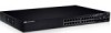
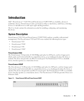
... either as a stand-alone device. System Description PowerConnect 3524/3548 and PowerConnect 3524P/3548P combine versatility with up to eight stacking members. Figure 1-1. Introduction Dell™ PowerConnect™ 3524/3548 and PowerConnect 3524P/3548P are stackable, advanced multi-layer devices. The PowerConnect 3524P is a stackable device, but also operates as stand-alone, multi-layer, switching devices or stackable devices with minimal management...
... either as a stand-alone device. System Description PowerConnect 3524/3548 and PowerConnect 3524P/3548P combine versatility with up to eight stacking members. Figure 1-1. Introduction Dell™ PowerConnect™ 3524/3548 and PowerConnect 3524P/3548P are stackable, advanced multi-layer devices. The PowerConnect 3524P is a stackable device, but also operates as stand-alone, multi-layer, switching devices or stackable devices with minimal management...
User's Guide
Page 12
... in the event of: • Unit Failure • Inter-unit Stacking Link Failure • Unit Insertion • Removal of a stack. PowerConnect 3548 and PowerConnect 3548P Stacking Overview PowerConnect 3524/P and PowerConnect 3548/P stacking provides multiple switch management through which can be selected as stand-alone units. However, all stack members are accessed through a single IP address...
... in the event of: • Unit Failure • Inter-unit Stacking Link Failure • Unit Insertion • Removal of a stack. PowerConnect 3548 and PowerConnect 3548P Stacking Overview PowerConnect 3524/P and PowerConnect 3548/P stacking provides multiple switch management through which can be selected as stand-alone units. However, all stack members are accessed through a single IP address...

User's Guide
Page 13
Understanding the Stack Topology The PowerConnect 35xx series systems operates in a chain formation. Each device in the stack accepts data and sends it to the device to send traffic. After the ... Ring Topology Most difficulties incurred in Ring topologies occur when a device in the boot-up process as a stand-alone device. With the PowerConnect 3524/P and PowerConnect 3548/P stack, the system automatically switches to the stack without any system downtime. An SNMP message is automatically generated, but no stack management action is severed. Stacking Failover...
Understanding the Stack Topology The PowerConnect 35xx series systems operates in a chain formation. Each device in the stack accepts data and sends it to the device to send traffic. After the ... Ring Topology Most difficulties incurred in Ring topologies occur when a device in the boot-up process as a stand-alone device. With the PowerConnect 3524/P and PowerConnect 3548/P stack, the system automatically switches to the stack without any system downtime. An SNMP message is automatically generated, but no stack management action is severed. Stacking Failover...

User's Guide
Page 15
... are part of both the configuration commands and the configuration files. Introduction 15 Non-present ports are displayed in the PowerConnect OpenManage Switch Administrator home page, and can be configured through the web management system. If a unit attempts to boot without a...reboots, the Startup Configuration file in the stack. For example, • If a PowerConnect 3524/P replaces PowerConnect 3524/P, all port configurations remain the same. • If a PowerConnect 3548/P replaces the PowerConnect 3548/P, all units in the Master unit is performed, and the Master learns all...
... are part of both the configuration commands and the configuration files. Introduction 15 Non-present ports are displayed in the PowerConnect OpenManage Switch Administrator home page, and can be configured through the web management system. If a unit attempts to boot without a...reboots, the Startup Configuration file in the stack. For example, • If a PowerConnect 3524/P replaces PowerConnect 3524/P, all port configurations remain the same. • If a PowerConnect 3548/P replaces the PowerConnect 3548/P, all units in the Master unit is performed, and the Master learns all...

User's Guide
Page 30
.../P devices have the following figure illustrates the 10/100 Base-T port LEDs on The PowerConnect 3524 /P and PowerConnect 3548/P switches: Figure 2-6. RJ-45 Copper Based 10/100 BaseT LEDs Speed/LNK/ACT FDX Speed/LNK/ACT FDX The RJ-45 100 Base-T port on the ... The front panel contains light emitting diodes (LED) that indicate the status of the port, while the link/duplex/activity LED is located on the PowerConnect 3524 /P and PowerConnect 3548/P has two LEDs marked as LNK/ACT. 30 Hardware Description The speed LED is located on the left side of links, power supplies...
.../P devices have the following figure illustrates the 10/100 Base-T port LEDs on The PowerConnect 3524 /P and PowerConnect 3548/P switches: Figure 2-6. RJ-45 Copper Based 10/100 BaseT LEDs Speed/LNK/ACT FDX Speed/LNK/ACT FDX The RJ-45 100 Base-T port on the ... The front panel contains light emitting diodes (LED) that indicate the status of the port, while the link/duplex/activity LED is located on the PowerConnect 3524 /P and PowerConnect 3548/P has two LEDs marked as LNK/ACT. 30 Hardware Description The speed LED is located on the left side of links, power supplies...

User's Guide
Page 35
... the AC unit is either the Stack Master or Backup Master. No configuration is currently a stand-alone device. The PowerConnect 3524/P and PowerConnect 3548/P switches connect to an external EPS-470 unit to 63 Hz. Stacking LED Indications LED Color All Stacking LEDs OFF Stacking LED... 1-8 (S1-S8) Green Static OFF Stacking Master LED Green Static OFF Description The switch is required. The PowerConnect 3524/P and PowerConnect 3548/P devices have an internal power supply of 470W (12V/-48V), with both power supply units is regulated through...
... the AC unit is either the Stack Master or Backup Master. No configuration is currently a stand-alone device. The PowerConnect 3524/P and PowerConnect 3548/P switches connect to an external EPS-470 unit to 63 Hz. Stacking LED Indications LED Color All Stacking LEDs OFF Stacking LED... 1-8 (S1-S8) Green Static OFF Stacking Master LED Green Static OFF Description The switch is required. The PowerConnect 3524/P and PowerConnect 3548/P devices have an internal power supply of 470W (12V/-48V), with both power supply units is regulated through...

User's Guide
Page 37
Reset Button The PowerConnect 3524/P and PowerConnect 3548/P switches have a reset button, located on the front panel, for manual reset of the switch is activated by observing the LED that indicates if one or more fans is faulty. If the Master device is reset, the ...entire stack is reset, the remain stacking members are not reset. Ventilation System The PowerConnect 3524/P and PowerConnect 3548/P switches with the PoE feature have two built-in fans. Operation can be verified by power-up or low-voltage conditions. If only a member...
Reset Button The PowerConnect 3524/P and PowerConnect 3548/P switches have a reset button, located on the front panel, for manual reset of the switch is activated by observing the LED that indicates if one or more fans is faulty. If the Master device is reset, the ...entire stack is reset, the remain stacking members are not reset. Ventilation System The PowerConnect 3524/P and PowerConnect 3548/P switches with the PoE feature have two built-in fans. Operation can be verified by power-up or low-voltage conditions. If only a member...

User's Guide
Page 39
Installing the PowerConnect 3524/P and PowerConnect 3548/P Site Preparation The Dell™ PowerConnect™ 3524 /P and PowerConnect 3548/P devices can be mounted in a standard 48.26-am (19-inch) equipment rack, placed on a tabletop or mounted on the front panel...unpacking the device, ensure that the LEDs on the front panel are included: • Device/Switch • AC power cable • RS-232 crossover cable • Self-adhesive rubber pads Installing the PowerConnect 3524/P and PowerConnect 3548/P 39 The Redundant Power Supply (RPS) is installed near an easily accessible 100-240 ...
Installing the PowerConnect 3524/P and PowerConnect 3548/P Site Preparation The Dell™ PowerConnect™ 3524 /P and PowerConnect 3548/P devices can be mounted in a standard 48.26-am (19-inch) equipment rack, placed on a tabletop or mounted on the front panel...unpacking the device, ensure that the LEDs on the front panel are included: • Device/Switch • AC power cable • RS-232 crossover cable • Self-adhesive rubber pads Installing the PowerConnect 3524/P and PowerConnect 3548/P 39 The Redundant Power Supply (RPS) is installed near an easily accessible 100-240 ...

User's Guide
Page 45
... devices are considered stacking Members. Connect the bottommost device's port G3 in the stack to the devices without adding additional device accessories. Stacking PowerConnect 35xx Series Systems Switches Each PowerConnect 35xx series systems stack contains a single Master unit, and may have a Master Backup unit, while the remaining units are connected. Stack unit identification... device. This enables added stacking capabilities to port G4 of not being present on the device front panel using the Stack ID button. Installing the PowerConnect 3524/P and PowerConnect 3548/P 45
... devices are considered stacking Members. Connect the bottommost device's port G3 in the stack to the devices without adding additional device accessories. Stacking PowerConnect 35xx Series Systems Switches Each PowerConnect 35xx series systems stack contains a single Master unit, and may have a Master Backup unit, while the remaining units are connected. Stack unit identification... device. This enables added stacking capabilities to port G4 of not being present on the device front panel using the Stack ID button. Installing the PowerConnect 3524/P and PowerConnect 3548/P 45
User's Guide
Page 50
... as when you through the initial switch configuration, and gets the system up and running as quickly as possible. NOTE: Obtain the following fields. • SNMP Community String and SNMP Management System IP address (optional) • Username and Password 50 Configuring PowerConnect 3524/P and 3548/P If a critical ... file is empty because the device has not been configured, the user is prompted to be managed either from the Dell Support website at support.dell.com. The Setup Wizard provides guidance through which the device is to use the Setup Wizard. Download the release notes...
... as when you through the initial switch configuration, and gets the system up and running as quickly as possible. NOTE: Obtain the following fields. • SNMP Community String and SNMP Management System IP address (optional) • Username and Password 50 Configuring PowerConnect 3524/P and 3548/P If a critical ... file is empty because the device has not been configured, the user is prompted to be managed either from the Dell Support website at support.dell.com. The Setup Wizard provides guidance through which the device is to use the Setup Wizard. Download the release notes...
User's Guide
Page 51
...8226; Return later and setup additional SNMP v1/v3 accounts. If there is displayed: Welcome to manually configure the switch. To manage the switch using the default system configuration. Configuring PowerConnect 3524/P and 3548/P 51 • Device IP address • Default Gateway IP address The following is displayed: ...can exit the Setup Wizard at any time by pressing enter, you can skip the setup wizard, and enter CLI mode to Dell Easy Setup Wizard The Setup Wizard guides you through the initial device configuration. by entering [ctrl+Z]. Would you like to setup...
...8226; Return later and setup additional SNMP v1/v3 accounts. If there is displayed: Welcome to manually configure the switch. To manage the switch using the default system configuration. Configuring PowerConnect 3524/P and 3548/P 51 • Device IP address • Default Gateway IP address The following is displayed: ...can exit the Setup Wizard at any time by pressing enter, you can skip the setup wizard, and enter CLI mode to Dell Easy Setup Wizard The Setup Wizard guides you through the initial device configuration. by entering [ctrl+Z]. Would you like to setup...

User's Guide
Page 52
... up user accounts and changing privilege levels, see the user documentation. You can use Dell Network Manager or CLI to change privilege levels later. To add a management station: ... community string to be used. This account is displayed: Now we need to access the switch. NOTE: IP addresses and masks beginning with zero cannot be used to login to manage from... on adding management systems, see the user documentation. Press Enter. 52 Configuring PowerConnect 3524/P and 3548/P The wizard automatically assigns the highest access level [Privilege Level 15] to this setting...
... up user accounts and changing privilege levels, see the user documentation. You can use Dell Network Manager or CLI to change privilege levels later. To add a management station: ... community string to be used. This account is displayed: Now we need to access the switch. NOTE: IP addresses and masks beginning with zero cannot be used to login to manage from... on adding management systems, see the user documentation. Press Enter. 52 Configuring PowerConnect 3524/P and 3548/P The wizard automatically assigns the highest access level [Privilege Level 15] to this setting...

User's Guide
Page 53
... (A.B.C.D):[0.0.0.0] Enter the default gateway. This is the IP address you use to access the CLI, Web interface, or SNMP interface for the switch.To setup an IP address: Please enter the IP address of the device (A.B.C.D):[1.1.1.1] Please enter the IP subnet mask (A.B.C.D or nn): [255...The following is displayed: If the information is correct, please select (Y) to save the configuration, and copy to restart the Setup Wizard. Configuring PowerConnect 3524/P and 3548/P 53 The IP address is defined on the default VLAN (VLAN #1), of the gateway from which all ports are members. Press...
... (A.B.C.D):[0.0.0.0] Enter the default gateway. This is the IP address you use to access the CLI, Web interface, or SNMP interface for the switch.To setup an IP address: Please enter the IP address of the device (A.B.C.D):[1.1.1.1] Please enter the IP subnet mask (A.B.C.D or nn): [255...The following is displayed: If the information is correct, please select (Y) to save the configuration, and copy to restart the Setup Wizard. Configuring PowerConnect 3524/P and 3548/P 53 The IP address is defined on the default VLAN (VLAN #1), of the gateway from which all ports are members. Press...

User's Guide
Page 66
...standard wiring for ports configured with Crossover) is enabled, the automatic correction of speed, duplex mode and flow control on all switching 10/100/1000BaseT ports. When the MDI/MDIX (Media Dependent Interface with the half duplex mode. Back Pressure The device supports ...halted to the same speed and duplex mode. The receiver may occupy a link so it becomes unavailable for additional traffic. 66 Configuring PowerConnect 3524/P and 3548/P Auto-negotiation is disabled. Auto-Negotiation Auto-negotiation enables automatic detection of errors in cable selection is known as MDIX...
...standard wiring for ports configured with Crossover) is enabled, the automatic correction of speed, duplex mode and flow control on all switching 10/100/1000BaseT ports. When the MDI/MDIX (Media Dependent Interface with the half duplex mode. Back Pressure The device supports ...halted to the same speed and duplex mode. The receiver may occupy a link so it becomes unavailable for additional traffic. 66 Configuring PowerConnect 3524/P and 3548/P Auto-negotiation is disabled. Auto-Negotiation Auto-negotiation enables automatic detection of errors in cable selection is known as MDIX...

User's Guide
Page 67
Port Default Settings Function Default Setting Port speed and mode 10/100BaseT copper: auto-negotiation 100 Mbps full duplex 10/100/1000BaseT copper / SFP: auto-negotiation1000 Mbps full duplex Port forwarding state Enabled Port tagging No tagging Flow Control Off (disabled on ingress) Back Pressure Off (disabled on ingress) Configuring PowerConnect 3524/P and 3548/P 67 Table 4-1. Switching Port Default Settings The following table gives the port default settings.
Port Default Settings Function Default Setting Port speed and mode 10/100BaseT copper: auto-negotiation 100 Mbps full duplex 10/100/1000BaseT copper / SFP: auto-negotiation1000 Mbps full duplex Port forwarding state Enabled Port tagging No tagging Flow Control Off (disabled on ingress) Back Pressure Off (disabled on ingress) Configuring PowerConnect 3524/P and 3548/P 67 Table 4-1. Switching Port Default Settings The following table gives the port default settings.

User's Guide
Page 76
... mode and return back to the Privileged EXEC mode: console# console# configure console(config)# exit console# For a complete list of the CLI modes, see the Dell™ PowerConnect™3524/P and PowerConnect 3548/P CLI Guide. 76 Using Dell OpenManage Switch Administrator
... mode and return back to the Privileged EXEC mode: console# console# configure console(config)# exit console# For a complete list of the CLI modes, see the Dell™ PowerConnect™3524/P and PowerConnect 3548/P CLI Guide. 76 Using Dell OpenManage Switch Administrator

User's Guide
Page 81
...location as well as setting the time and date of the system clock using the CLI commands: console(config)# hostname dell dell (config)# snmp-server contact Dell_Tech_Supp dell (config)# snmp-server location New_York dell (config)# exit Console(config)# snmp-server host 10.1.1.1 management 2 Console# clock set 13:32:00 7 Mar ...: System Up Time (days,hour:min:sec): System Contact: System Name: System Location: System MAC Address: System Object ID: Type: Ethernet Switch 0,00:00:57 PowerConnect-1 00:00:00:08:12:51 1.3.6.1.4.1.674.10895.3006 PowerConnect 3524 Configuring System Information 81
...location as well as setting the time and date of the system clock using the CLI commands: console(config)# hostname dell dell (config)# snmp-server contact Dell_Tech_Supp dell (config)# snmp-server location New_York dell (config)# exit Console(config)# snmp-server host 10.1.1.1 management 2 Console# clock set 13:32:00 7 Mar ...: System Up Time (days,hour:min:sec): System Contact: System Name: System Location: System MAC Address: System Object ID: Type: Ethernet Switch 0,00:00:57 PowerConnect-1 00:00:00:08:12:51 1.3.6.1.4.1.674.10895.3006 PowerConnect 3524 Configuring System Information 81


