SCSI Backplane Daughter Card (.pdf)
Page 3
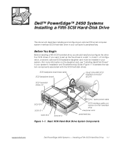
... four SCSI drives. SCSI backplane board data cable SCSI backplane board Ultra3 (Ultra160) SCSI interface connector (SCSI1) SCSI hard-disk drives (4) SCSI ID 0 SCSI ID 1 SCSI ID 2 SCSI ID 3 spare power cable SCSI interface cable connection for fifth hard-disk drive interposer card peripheral bay Figure 1-1. Basic SCSI Hard-Disk Drive System Components support.dell.com Dell PowerEdge 2450 Systems - Before You Begin Before installing a fifth SCSI hard-disk drive, you want to set up the five drives in a split 1 x 2 and 1 x 3 configuration, a second, optional SCSI backplane daughter card...
... four SCSI drives. SCSI backplane board data cable SCSI backplane board Ultra3 (Ultra160) SCSI interface connector (SCSI1) SCSI hard-disk drives (4) SCSI ID 0 SCSI ID 1 SCSI ID 2 SCSI ID 3 spare power cable SCSI interface cable connection for fifth hard-disk drive interposer card peripheral bay Figure 1-1. Basic SCSI Hard-Disk Drive System Components support.dell.com Dell PowerEdge 2450 Systems - Before You Begin Before installing a fifth SCSI hard-disk drive, you want to set up the five drives in a split 1 x 2 and 1 x 3 configuration, a second, optional SCSI backplane daughter card...
SCSI Backplane Daughter Card (.pdf)
Page 4
... Figure 1-2). 1-2 Dell PowerEdge 2450 Systems - These cables include the system board interface cable, cooling fan wiring harness, interposer board power cable, and control panel cable (see "Checking Inside the System" in this section, you must remove the peripheral bay and install a special hard-disk drive cage in a 1 x 5 configuration, attach a single SCSI host adapter to connector SCSIA on top of the peripherals bay (see Figure 1-1). To operate the five drives in the bay. Open the system covers. 3. In this...
... Figure 1-2). 1-2 Dell PowerEdge 2450 Systems - These cables include the system board interface cable, cooling fan wiring harness, interposer board power cable, and control panel cable (see "Checking Inside the System" in this section, you must remove the peripheral bay and install a special hard-disk drive cage in a 1 x 5 configuration, attach a single SCSI host adapter to connector SCSIA on top of the peripherals bay (see Figure 1-1). To operate the five drives in the bay. Open the system covers. 3. In this...
SCSI Backplane Daughter Card (.pdf)
Page 5
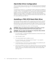
thumbscrew hard-disk drive cage rails (2) peripheral bay Figure 1-3. Connectors on the Interposer Board 6. Installing the Hard-Disk Drive Cage in the Peripheral Bay support.dell.com Dell PowerEdge 2450 Systems - Loosen the thumbscrew at the back corner of the peripheral bay (see Figure 1-3). Installing a Fifth SCSI Hard-Disk Drive 1-3 cooling fan wiring harness connector system board interface cable connector interposer board power cable connector control panel cable connector diskette drive/CD-ROM drive interface connector Figure 1-2.
thumbscrew hard-disk drive cage rails (2) peripheral bay Figure 1-3. Connectors on the Interposer Board 6. Installing the Hard-Disk Drive Cage in the Peripheral Bay support.dell.com Dell PowerEdge 2450 Systems - Loosen the thumbscrew at the back corner of the peripheral bay (see Figure 1-3). Installing a Fifth SCSI Hard-Disk Drive 1-3 cooling fan wiring harness connector system board interface cable connector interposer board power cable connector control panel cable connector diskette drive/CD-ROM drive interface connector Figure 1-2.

SCSI Backplane Daughter Card (.pdf)
Page 6
... plastic insert to the SCSI cable connector on the fifth-drive backplane board at the back corner of the system chassis. Connect one inch); Attach the other drive is empty, remove the rectangular plastic insert from the chassis. 9. Connectors on the main SCSI backplane board (see Figure 1-1) to release the insert from the front of the cage. 13. Connect the SCSI interface cable (see Figure 5). 1-4 Dell PowerEdge 2450 Systems - then slide the...
... plastic insert to the SCSI cable connector on the fifth-drive backplane board at the back corner of the system chassis. Connect one inch); Attach the other drive is empty, remove the rectangular plastic insert from the chassis. 9. Connectors on the main SCSI backplane board (see Figure 1-1) to release the insert from the front of the cage. 13. Connect the SCSI interface cable (see Figure 5). 1-4 Dell PowerEdge 2450 Systems - then slide the...

SCSI Backplane Daughter Card (.pdf)
Page 7
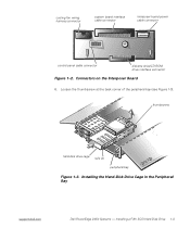
Install the fifth hard-disk drive by aligning the edge of the hard-disk drive carrier with the opening in the front of the hard-disk drive cage, and insert the carrier into the drive cage (see Figure 1-2). 18. SCSI Hard-Disk Drive Carrier support.dell.com Dell PowerEdge 2450 Systems - Ultra3 SCSI cable connector (SCSIA) Ultra3 SCSI cable connector (SCSIB) interface cable connector for fifth-drive board (DRIVE5) Figure 1-5. Connect the spare power cable leading from the power supply distribution board (see Figure 4). 17. Connectors on the fifth-drive backplane board (see Figure...
Install the fifth hard-disk drive by aligning the edge of the hard-disk drive carrier with the opening in the front of the hard-disk drive cage, and insert the carrier into the drive cage (see Figure 1-2). 18. SCSI Hard-Disk Drive Carrier support.dell.com Dell PowerEdge 2450 Systems - Ultra3 SCSI cable connector (SCSIA) Ultra3 SCSI cable connector (SCSIB) interface cable connector for fifth-drive board (DRIVE5) Figure 1-5. Connect the spare power cable leading from the power supply distribution board (see Figure 4). 17. Connectors on the fifth-drive backplane board (see Figure...
SCSI Backplane Daughter Card (.pdf)
Page 8
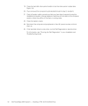
... you removed the computer's optional plastic bezel in your Installation and Troubleshooting Guide. 1-6 Dell PowerEdge 2450 Systems - For information, see Figure 1-6). 20. Close the hard-disk drive carrier handle to their AC power sources, and turn them on the computer covers or block the airflow of the fans or cooling vents. 22. Installing a Fifth SCSI Hard-Disk Drive If the hard-disk drive is a new drive, run the Dell Diagnostics to test the drive. Check all system cable connections that they...
... you removed the computer's optional plastic bezel in your Installation and Troubleshooting Guide. 1-6 Dell PowerEdge 2450 Systems - For information, see Figure 1-6). 20. Close the hard-disk drive carrier handle to their AC power sources, and turn them on the computer covers or block the airflow of the fans or cooling vents. 22. Installing a Fifth SCSI Hard-Disk Drive If the hard-disk drive is a new drive, run the Dell Diagnostics to test the drive. Check all system cable connections that they...

Activating the Dell PERC 3/Si (.pdf)
Page 3
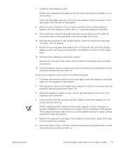
... the system from the chassis. Prepare the expansion card for your Dell PowerEdge 2450 system: Installing and removing expansion cards Small computer system interface (SCSI) hard-disk drive support Installing an upgrade microprocessor in PowerEdge 2450 systems To install an expansion card, perform the following steps. 1. This document updates information on configuring the card, making internal connections, or otherwise customizing the card for installation, and open the system doors. support.dell.com Dell PowerEdge 2450 Systems Information Update 1-1 Turn off the system...
... the system from the chassis. Prepare the expansion card for your Dell PowerEdge 2450 system: Installing and removing expansion cards Small computer system interface (SCSI) hard-disk drive support Installing an upgrade microprocessor in PowerEdge 2450 systems To install an expansion card, perform the following steps. 1. This document updates information on configuring the card, making internal connections, or otherwise customizing the card for installation, and open the system doors. support.dell.com Dell PowerEdge 2450 Systems Information Update 1-1 Turn off the system...

Activating the Dell PERC 3/Si (.pdf)
Page 4
Open the expansion-card latch (see Figure 1-1). expansion-card latch expansion card card-edge connector expansion-card connector riser board 1-2 Dell PowerEdge 2450 Systems Information Update card guide expansion-card cage securing lever expansion-card cage 4. Rotate the lever upward until it stops in an upright position. 5. Locate the expansion-card cage securing lever (see Figure 1-2) and remove the filler bracket from the chassis. 6. Lift the expansion-card cage up and away from the expansion slot.
Open the expansion-card latch (see Figure 1-1). expansion-card latch expansion card card-edge connector expansion-card connector riser board 1-2 Dell PowerEdge 2450 Systems Information Update card guide expansion-card cage securing lever expansion-card cage 4. Rotate the lever upward until it stops in an upright position. 5. Locate the expansion-card cage securing lever (see Figure 1-2) and remove the filler bracket from the chassis. 6. Lift the expansion-card cage up and away from the expansion slot.
Activating the Dell PERC 3/Si (.pdf)
Page 5
... the expansion-card connector on the card guide over an empty expansion slot is flush with the brackets on your work surface. With the securing lever in step 3. Make sure the riser board is aligned. 11. See the documentation that the riser board lies horizontally on either side of the system. support.dell.com Dell PowerEdge 2450 Systems Information Update 1-3 To remove an expansion card, perform the following steps: 1. Install...
... the expansion-card connector on the card guide over an empty expansion slot is flush with the brackets on your work surface. With the securing lever in step 3. Make sure the riser board is aligned. 11. See the documentation that the riser board lies horizontally on either side of the system. support.dell.com Dell PowerEdge 2450 Systems Information Update 1-3 To remove an expansion card, perform the following steps: 1. Install...
Activating the Dell PERC 3/Si (.pdf)
Page 6
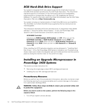
... Installation and Troubleshooting Guide, make sure to slide in this section, take a few moments to read the following steps in "Using the System Setup Program," of your Dell PowerEdge 2450 Systems User's Guide have been combined to read as follows: SCSI/RAID Controller Selections are interchangeable. The subsections describing SCSI and redundant array of the procedures in the daughter card until it to SCSI Enabled, Channel A and Channel B display SCSI...
... Installation and Troubleshooting Guide, make sure to slide in this section, take a few moments to read the following steps in "Using the System Setup Program," of your Dell PowerEdge 2450 Systems User's Guide have been combined to read as follows: SCSI/RAID Controller Selections are interchangeable. The subsections describing SCSI and redundant array of the procedures in the daughter card until it to SCSI Enabled, Channel A and Channel B display SCSI...

Activating the Dell PERC 3/Si (.pdf)
Page 7
.... Update the embedded server management (ESM) firmware. support.dell.com Dell PowerEdge 2450 Systems Information Update 1-5 Also, disconnect any telephone or telecommunication lines from their power sources. Don't touch the components or contacts on the cable itself. Ground yourself by touching an unpainted metal surface on the chassis, such as a microprocessor chip by its edges, not by its pins. Some cables have a connector with care. Hold a card...
.... Update the embedded server management (ESM) firmware. support.dell.com Dell PowerEdge 2450 Systems Information Update 1-5 Also, disconnect any telephone or telecommunication lines from their power sources. Don't touch the components or contacts on the cable itself. Ground yourself by touching an unpainted metal surface on the chassis, such as a microprocessor chip by its edges, not by its pins. Some cables have a connector with care. Hold a card...
Activating the Dell PERC 3/Si (.pdf)
Page 8
... included with the upgrade kit, update your BIOS with the version contained on that diskette by performing the following steps. Insert the ESM firmware diskette into the diskette drive. 2. After the message appears on the screen, remove the BIOS diskette from the diskette drive and follow the instructions on the screen to save the current system configuration information. 1-6 Dell PowerEdge 2450 Systems Information Update Use the RCU diskette...
... included with the upgrade kit, update your BIOS with the version contained on that diskette by performing the following steps. Insert the ESM firmware diskette into the diskette drive. 2. After the message appears on the screen, remove the BIOS diskette from the diskette drive and follow the instructions on the screen to save the current system configuration information. 1-6 Dell PowerEdge 2450 Systems Information Update Use the RCU diskette...
Activating the Dell PERC 3/Si (.pdf)
Page 9
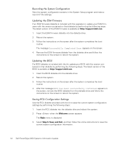
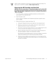
... blower power cable from the power supplies, you avoid the need to use excessive force to remove the air blower. Open the system cover. a. Push firmly on the outside of the power supply enclosure beside the narrower front part of the air blower. See your system's Installation and Troubleshooting Guide for specific instructions, if needed. 3. NOTE: The RCU recognizes microprocessors operating at the top back of the chassis. e. Turn...
... blower power cable from the power supplies, you avoid the need to use excessive force to remove the air blower. Open the system cover. a. Push firmly on the outside of the power supply enclosure beside the narrower front part of the air blower. See your system's Installation and Troubleshooting Guide for specific instructions, if needed. 3. NOTE: The RCU recognizes microprocessors operating at the top back of the chassis. e. Turn...
Activating the Dell PERC 3/Si (.pdf)
Page 12
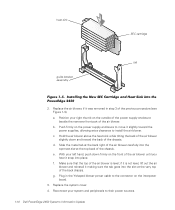
... chassis. if it was removed in the Y-shaped blower power cable to the connector on the power supply enclosure to install the air blower. Replace the system cover. 4. b. d. e. Slide the metal tab at the top back of the previous procedure (see Figure 1-3). Replace the air blower, if it is level; f. c. g. With your system and peripherals to their power sources. 1-10 Dell PowerEdge 2450 Systems Information Update heat...
... chassis. if it was removed in the Y-shaped blower power cable to the connector on the power supply enclosure to install the air blower. Replace the system cover. 4. b. d. e. Slide the metal tab at the top back of the previous procedure (see Figure 1-3). Replace the air blower, if it is level; f. c. g. With your system and peripherals to their power sources. 1-10 Dell PowerEdge 2450 Systems Information Update heat...

Microprocessor Upgrade Installation Guide (.pdf)
Page 3
... other remote connection to log into the port concentrator, you can be used under the disk operating system (DOS) for tasks such as setting up a common basic input/output system (BIOS) configuration or setting up a redundant array of 80 x 25 characters • 9600, 19.2K, 57.6K, or 115.2K bits per second (bps) via a shared modem. Console Redirection support.dell.com Console redirection allows you to manage...
... other remote connection to log into the port concentrator, you can be used under the disk operating system (DOS) for tasks such as setting up a common basic input/output system (BIOS) configuration or setting up a redundant array of 80 x 25 characters • 9600, 19.2K, 57.6K, or 115.2K bits per second (bps) via a shared modem. Console Redirection support.dell.com Console redirection allows you to manage...

Microprocessor Upgrade Installation Guide (.pdf)
Page 4
... listed in this document assume that you are using other terminal emulation software, see the help file for that you to the system setup program and select ANSI as your current version of ASCII characters. Used for the new connection and select any name for utility partition applications or DOS. Used for POST. Used for utility partition applications or DOS. Configuring Console Redirection on the Server...
... listed in this document assume that you are using other terminal emulation software, see the help file for that you to the system setup program and select ANSI as your current version of ASCII characters. Used for the new connection and select any name for utility partition applications or DOS. Used for POST. Used for utility partition applications or DOS. Configuring Console Redirection on the Server...

Microprocessor Upgrade Installation Guide (.pdf)
Page 5
... Bits per second. Set Data bits to Hardware. 10. Set Flow control to 8. 7. Configuring the Terminal Settings After you must upgrade your terminal emulation software. In HyperTerminal, click File, click Properties, and select the Settings tab. 2. If you do not have a Dell system, you should be the same as field is displayed. 5. Set Parity to pull-down menu, select a COM port available on the server. Change the Emulation setting from...
... Bits per second. Set Data bits to Hardware. 10. Set Flow control to 8. 7. Configuring the Terminal Settings After you must upgrade your terminal emulation software. In HyperTerminal, click File, click Properties, and select the Settings tab. 2. If you do not have a Dell system, you should be the same as field is displayed. 5. Set Parity to pull-down menu, select a COM port available on the server. Change the Emulation setting from...

Microprocessor Upgrade Installation Guide (.pdf)
Page 6
... using Dell OpenManage™ Server Assistant version 6.3.1 or later. Tables 2 and 3 list the escape sequence that you are sending an escape sequence rather than escaping out of your function keys. To use console redirection to shut down a system and troubleshoot it or to change small computer system interface (SCSI) BIOS configurations, perform the following : • Enter the system setup program. • Enter the SCSI setup menus. • Run utilities...
... using Dell OpenManage™ Server Assistant version 6.3.1 or later. Tables 2 and 3 list the escape sequence that you are sending an escape sequence rather than escaping out of your function keys. To use console redirection to shut down a system and troubleshoot it or to change small computer system interface (SCSI) BIOS configurations, perform the following : • Enter the system setup program. • Enter the SCSI setup menus. • Run utilities...
Installation and Troubleshooting Guide (.pdf)
Page 5
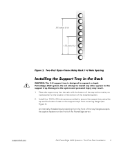
... the support tray using the top and the bottom holes on the front of the installed system. 2. Two-Post Rack Installation 3 Two-Post Open-Frame Relay Rack 1-U Hole Spacing Installing the Support Tray in this support tray. An internally threaded stud projecting from the front of the tray flanges accepts the captive fastener on the support tray's front-mounting flange (see Figure 3). Preliminary 9/27/01 Dell PowerEdge 2450...
... the support tray using the top and the bottom holes on the front of the installed system. 2. Two-Post Rack Installation 3 Two-Post Open-Frame Relay Rack 1-U Hole Spacing Installing the Support Tray in this support tray. An internally threaded stud projecting from the front of the tray flanges accepts the captive fastener on the support tray's front-mounting flange (see Figure 3). Preliminary 9/27/01 Dell PowerEdge 2450...
Installation and Troubleshooting Guide (.pdf)
Page 7
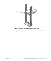
support.dell.com DELL CONFIDENTIAL - (Rev. 11/3/98) FILE LOCATION: C:\Dell\docs\2450\2post\81HFFts0.fm captive fasteners Figure 4. Attach the front bezel, if one is available, to the system (see the Installation and Troubleshooting Guide for instructions). Two-Post Rack Installation 5 Preliminary 9/27/01 Dell PowerEdge 2450 Systems - This completes the two-post rack installation. Securing the Computer System in the Rack 4.
support.dell.com DELL CONFIDENTIAL - (Rev. 11/3/98) FILE LOCATION: C:\Dell\docs\2450\2post\81HFFts0.fm captive fasteners Figure 4. Attach the front bezel, if one is available, to the system (see the Installation and Troubleshooting Guide for instructions). Two-Post Rack Installation 5 Preliminary 9/27/01 Dell PowerEdge 2450 Systems - This completes the two-post rack installation. Securing the Computer System in the Rack 4.


