

Getting Started Guide
Page 6
...or SAS drives are data only. • Support for Intel EM64T 4 Getting Started With Your System This option requires a dedicated PCI slot. • One 420-W power supply. The following internal hard-drive configurations: - For information about using the system diagnostics, see "Installing Drives" in high-resolution modes. • SATA or SAS device drivers that allow the operating system to communicate with integrated drive controllers. - Up to four internal, 1-inch, SATA hard drives with devices attached to the optional SAS controller card or backplane. • Optional remote...
...or SAS drives are data only. • Support for Intel EM64T 4 Getting Started With Your System This option requires a dedicated PCI slot. • One 420-W power supply. The following internal hard-drive configurations: - For information about using the system diagnostics, see "Installing Drives" in high-resolution modes. • SATA or SAS device drivers that allow the operating system to communicate with integrated drive controllers. - Up to four internal, 1-inch, SATA hard drives with devices attached to the optional SAS controller card or backplane. • Optional remote...

Hardware Owner's Manual (PDF)
Page 5
...Fan 68 Power Supply 69 Removing the Power Supply 69 Replacing the Power Supply 70 Expansion Cards 71 Installing an Expansion Card 72 Removing an Expansion Card 73 Replacing the SAS Controller Card Battery 75 Memory 76 General Memory Module Installation Guidelines 76 Installing Memory Modules 76 Removing Memory Modules 78 Microprocessor 78 Removing the Processor 79 Installing a Processor 81 Installing a RAC Card 83 System Battery 83 Replacing the System Battery 83 Front I/O Panel (Service-Only Parts Procedure 85 Removing the Control Panel Assembly and Chassis-Intrusion Switch...
...Fan 68 Power Supply 69 Removing the Power Supply 69 Replacing the Power Supply 70 Expansion Cards 71 Installing an Expansion Card 72 Removing an Expansion Card 73 Replacing the SAS Controller Card Battery 75 Memory 76 General Memory Module Installation Guidelines 76 Installing Memory Modules 76 Removing Memory Modules 78 Microprocessor 78 Removing the Processor 79 Installing a Processor 81 Installing a RAC Card 83 System Battery 83 Replacing the System Battery 83 Front I/O Panel (Service-Only Parts Procedure 85 Removing the Control Panel Assembly and Chassis-Intrusion Switch...

Hardware Owner's Manual (PDF)
Page 10
... your RAID card. If you have the optional Dell Remote Access Controller (DRAC), this keystroke allows access to configure NIC settings for experienced users or technicians. Table 1-1. This keystroke allows you to the system or documentation or advanced technical reference material intended for PXE boot. See the BMC User's Guide for more information on setup and use of DRAC. 10 About Your System For more information, see the documentation for your SAS adapter User's Guide...
... your RAID card. If you have the optional Dell Remote Access Controller (DRAC), this keystroke allows access to configure NIC settings for experienced users or technicians. Table 1-1. This keystroke allows you to the system or documentation or advanced technical reference material intended for PXE boot. See the BMC User's Guide for more information on setup and use of DRAC. 10 About Your System For more information, see the documentation for your SAS adapter User's Guide...

Hardware Owner's Manual (PDF)
Page 16
...operating condition after POST. 16 About Your System Diagnostic Indicator Codes (continued) Code Causes Possible USB failure. A B C D No memory modules detected. The system is in your system. Possible system board resource and/or system board hardware failure. See "Getting Help" on page 100. Ensure that the diskette drive, optical drive, and hard drive(s) are properly connected. If the problem persists, see "Getting Help" on error. Table 1-4. A B C D A B C D A B C D A B C D A B C D A B C D = yellow = green = off Memory configuration See "Troubleshooting System Memory...
...operating condition after POST. 16 About Your System Diagnostic Indicator Codes (continued) Code Causes Possible USB failure. A B C D No memory modules detected. The system is in your system. Possible system board resource and/or system board hardware failure. See "Getting Help" on page 100. Ensure that the diskette drive, optical drive, and hard drive(s) are properly connected. If the problem persists, see "Getting Help" on error. Table 1-4. A B C D A B C D A B C D A B C D A B C D A B C D = yellow = green = off Memory configuration See "Troubleshooting System Memory...

Hardware Owner's Manual (PDF)
Page 23
...failure Faulty hard-disk drive. If the problem persists, see "Troubleshooting Expansion Cards" on page 108. About Your System 23 faulty system board. Replace the diskette. Remove and reseat the expansion cards. Check for a BIOS update. drive configuration error SATA Port n hard disk drive failure SATA Port n hard disk drive auto-sensing error Corrective Actions Install the NVRAM_CLR jumper and reboot the system. Table 1-6. Remote Configuration update attempt failed ROM bad checksum = address System could not implement Remote Configuration request. Replace the hard-disk...
...failure Faulty hard-disk drive. If the problem persists, see "Troubleshooting Expansion Cards" on page 108. About Your System 23 faulty system board. Replace the diskette. Remove and reseat the expansion cards. Check for a BIOS update. drive configuration error SATA Port n hard disk drive failure SATA Port n hard disk drive auto-sensing error Corrective Actions Install the NVRAM_CLR jumper and reboot the system. Table 1-6. Remote Configuration update attempt failed ROM bad checksum = address System could not implement Remote Configuration request. Replace the hard-disk...

Hardware Owner's Manual (PDF)
Page 24
... appropriate drive installed in the System Setup program. If the problem persists, see "Troubleshooting SATA Hard Drives" on page 105 or "Troubleshooting a SAS RAID Controller" on page 121. 24 About Your System See "Troubleshooting the System Battery" on page 29. faulty system board. Ensure that all memory modules are properly installed. Table 1-6. See "Using the System Setup Program" on page 98. See "Troubleshooting System Memory" on page 121." Faulty memory module. Faulty memory module. If the problem...
... appropriate drive installed in the System Setup program. If the problem persists, see "Troubleshooting SATA Hard Drives" on page 105 or "Troubleshooting a SAS RAID Controller" on page 121. 24 About Your System See "Troubleshooting the System Battery" on page 29. faulty system board. Ensure that all memory modules are properly installed. Table 1-6. See "Using the System Setup Program" on page 98. See "Troubleshooting System Memory" on page 121." Faulty memory module. Faulty memory module. If the problem...

Hardware Owner's Manual (PDF)
Page 34
... user-selectable settings. CPU Information Screen (continued) Option Demand-Based Power Management (Disabled default) Processor 1 ID Description Enables or disables demand-based power management. Disabling the USB ports makes system resources available for the integrated 10/100/1000 NIC. A submenu displays: - When using the Read-Only setting, the drive cannot be set to accommodate a controller card installed in an expansion slot. Table 2-4. Displays the family, model number, and details for each channel of Cores - 64-bit Technology Integrated Devices Screen Table 2-4 lists...
... user-selectable settings. CPU Information Screen (continued) Option Demand-Based Power Management (Disabled default) Processor 1 ID Description Enables or disables demand-based power management. Disabling the USB ports makes system resources available for the integrated 10/100/1000 NIC. A submenu displays: - When using the Read-Only setting, the drive cannot be set to accommodate a controller card installed in an expansion slot. Table 2-4. Displays the family, model number, and details for each channel of Cores - 64-bit Technology Integrated Devices Screen Table 2-4 lists...

Hardware Owner's Manual (PDF)
Page 37
... can disable the password by a jumper setting, the system password is Disabled, and you cannot change or delete an existing password, you must know the password have full use additional forms of protection, such as data encryption programs. NOTICE: Anyone can access the data stored on your system if you leave the system running and unattended without the system password feature enabled. If the Password Status option is...
... can disable the password by a jumper setting, the system password is Disabled, and you cannot change or delete an existing password, you must know the password have full use additional forms of protection, such as data encryption programs. NOTICE: Anyone can access the data stored on your system if you leave the system running and unattended without the system password feature enabled. If the Password Status option is...

Hardware Owner's Manual (PDF)
Page 87
... "Removing the Cooling Shroud" on the system board and insert the cable in its guide bracket. 4 Guide the chassis-intrusion switch cable through the opening above the control panel slot. 3 Connect the control panel assembly cable connector to the FRONT_PANEL connector on page 64. 6 If the system has cabled SAS drives or SATA drives, note the relative location of the interface cable connections between the system board and the drives, so you can get hot during operation. Installing the Control Panel Assembly 1 Insert the control panel...
... "Removing the Cooling Shroud" on the system board and insert the cable in its guide bracket. 4 Guide the chassis-intrusion switch cable through the opening above the control panel slot. 3 Connect the control panel assembly cable connector to the FRONT_PANEL connector on page 64. 6 If the system has cabled SAS drives or SATA drives, note the relative location of the interface cable connections between the system board and the drives, so you can get hot during operation. Installing the Control Panel Assembly 1 Insert the control panel...

Hardware Owner's Manual (PDF)
Page 99
... discharge. 1 Run the appropriate diagnostic test. See "Opening the System" on page 111. 2 Open the system. See "Using Dell PowerEdge Diagnostics" on page 43. See "Closing the System" on page 69. If the problem persists, remove the faulty power supply. See "Power Supply" on page 47. 4 Ensure that the power supply is properly installed by removing and reinstalling it is amber. • Systems management software issues a fan-related error message. • Fan status indicator indicates a problem with the fan.
... discharge. 1 Run the appropriate diagnostic test. See "Opening the System" on page 111. 2 Open the system. See "Using Dell PowerEdge Diagnostics" on page 43. See "Closing the System" on page 69. If the problem persists, remove the faulty power supply. See "Power Supply" on page 47. 4 Ensure that the power supply is properly installed by removing and reinstalling it is amber. • Systems management software issues a fan-related error message. • Fan status indicator indicates a problem with the fan.
Hardware Owner's Manual (PDF)
Page 101
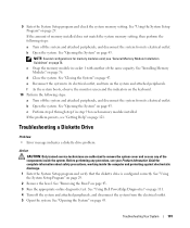
... 43. See "Installing Memory Modules" on page 29. 2 Remove the bezel. Troubleshooting a Diskette Drive Problem • Error message indicates a diskette drive problem. See "Using the System Setup Program" on page 76. f As the system boots, observe the monitor screen and the indicators on page 111. 4 Turn off the system and attached peripherals, and disconnect the system from the electrical outlet. 5 Open the system. See "Using Dell PowerEdge Diagnostics" on the keyboard...
... 43. See "Installing Memory Modules" on page 29. 2 Remove the bezel. Troubleshooting a Diskette Drive Problem • Error message indicates a diskette drive problem. See "Using the System Setup Program" on page 76. f As the system boots, observe the monitor screen and the indicators on page 111. 4 Turn off the system and attached peripherals, and disconnect the system from the electrical outlet. 5 Open the system. See "Using Dell PowerEdge Diagnostics" on the keyboard...

Hardware Owner's Manual (PDF)
Page 105
... system to remove the system cover and access any procedure, see "Troubleshooting a SATA Hard Drive in "Running the System Diagnostics." If the problem persists, see Figure 3-13). NOTICE: This troubleshooting procedure can destroy data stored on page 47. See the operating system documentation for the RAID. c Verify that the cable connections between the hard drive(s) and the drive controller are correct, whether the connections are to the operating system. 3 Ensure that the required device drivers for...
... system to remove the system cover and access any procedure, see "Troubleshooting a SATA Hard Drive in "Running the System Diagnostics." If the problem persists, see Figure 3-13). NOTICE: This troubleshooting procedure can destroy data stored on page 47. See the operating system documentation for the RAID. c Verify that the cable connections between the hard drive(s) and the drive controller are correct, whether the connections are to the operating system. 3 Ensure that the required device drivers for...

Hardware Owner's Manual (PDF)
Page 106
... identify system board connectors, see "System Board Connectors" on page 118. 6 If the hard drive is the boot drive, ensure that the drive is configured properly. See the operating system documentation. 12 If possible, restore the files to the next step. 11 Format and partition the hard drive. See "Using Dell PowerEdge Diagnostics" on page 111. 2 Ensure that the required device drivers are installed and are authorized to remove the system cover and access any...
... identify system board connectors, see "System Board Connectors" on page 118. 6 If the hard drive is the boot drive, ensure that the drive is configured properly. See the operating system documentation. 12 If possible, restore the files to the next step. 11 Format and partition the hard drive. See "Using Dell PowerEdge Diagnostics" on page 111. 2 Ensure that the required device drivers are installed and are authorized to remove the system cover and access any...

Hardware Owner's Manual (PDF)
Page 107
... the computer and protecting against electrostatic discharge. 1 Run the appropriate online diagnostic test. See the operating system documentation. 13 If possible, restore the files to enter the configuration utility program: • for a SAS controller • for a SAS RAID controller See the controller's documentation for complete information about configuration settings. See "Using Dell PowerEdge Diagnostics" on page 43. 7 If the hard drive is the boot drive, ensure that the SAS RAID controller is configured and connected properly. Troubleshooting Your System 107
... the computer and protecting against electrostatic discharge. 1 Run the appropriate online diagnostic test. See the operating system documentation. 13 If possible, restore the files to enter the configuration utility program: • for a SAS controller • for a SAS RAID controller See the controller's documentation for complete information about configuration settings. See "Using Dell PowerEdge Diagnostics" on page 43. 7 If the hard drive is the boot drive, ensure that the SAS RAID controller is configured and connected properly. Troubleshooting Your System 107
Hardware Owner's Manual (PDF)
Page 147
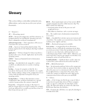
... a change to a disk drive for quick data retrieval. Baseboard management controller. Your system contains an expansion bus that is turned off and then back on. When a program makes a request to the configuration of three beeps is located. Advanced Configuration and Power Interface. backup - backup battery - For example, one beep, followed by turning the system off . The BIOS controls the following: • Communications between the components of a program or data file. BMC - The temperature...
... a change to a disk drive for quick data retrieval. Baseboard management controller. Your system contains an expansion bus that is turned off and then back on. When a program makes a request to the configuration of three beeps is located. Advanced Configuration and Power Interface. backup - backup battery - For example, one beep, followed by turning the system off . The BIOS controls the following: • Communications between the components of a program or data file. BMC - The temperature...

Hardware Owner's Manual (PDF)
Page 148
... of DRAM chips. EEPROM - ERA - controller - Central processing unit. See processor. ESM - CPU - Domain Name System. Dynamic random-access memory. ECC - expansion card - Dynamic Host Configuration Protocol. directory - DMI - DMI enables the management of -band," server management on the system board. cm - Centimeter(s). A chip that branch off them. Double-data rate. DMA - DVD - Electrostatic discharge. An expansion card adds some other program to perform remote, or "out-of your network server using a remote access controller.
... of DRAM chips. EEPROM - ERA - controller - Central processing unit. See processor. ESM - CPU - Domain Name System. Dynamic random-access memory. ECC - expansion card - Dynamic Host Configuration Protocol. directory - DMI - DMI enables the management of -band," server management on the system board. cm - Centimeter(s). A chip that branch off them. Double-data rate. DMA - DVD - Electrostatic discharge. An expansion card adds some other program to perform remote, or "out-of your network server using a remote access controller.

Hardware Owner's Manual (PDF)
Page 152
... configuration software for the Windows operating environment. Data stored in memory that has two or more processors connected via a high-bandwidth link and managed by changing settings in a series, you call Dell for video adapters with faster data transmission rates than previous standards. When you start -up file for peripherals, and various ROM chips. TCP/IP - An I /O bus interface with greater resolution and color display capabilities than standard ports. simple disk volume - Used to remotely monitor...
... configuration software for the Windows operating environment. Data stored in memory that has two or more processors connected via a high-bandwidth link and managed by changing settings in a series, you call Dell for video adapters with faster data transmission rates than previous standards. When you start -up file for peripherals, and various ROM chips. TCP/IP - An I /O bus interface with greater resolution and color display capabilities than standard ports. simple disk volume - Used to remotely monitor...

Hardware Owner's Manual (PDF)
Page 153
... cable. The amount of video memory installed primarily influences the number of pixels up file for network clients. A start Windows, it consults the win.ini file to Linux, is running. UTP - Volt(s). Video graphics array. video resolution - To display a program at a chosen resolution with the monitor) your system's RAM. win.ini file - Windows Server® 2003 - uplink port - utility - memory, disk drives, or printers, for the Windows operating environment. Video drivers may be integrated into an expansion slot...
... cable. The amount of video memory installed primarily influences the number of pixels up file for network clients. A start Windows, it consults the win.ini file to Linux, is running. UTP - Volt(s). Video graphics array. video resolution - To display a program at a chosen resolution with the monitor) your system's RAM. win.ini file - Windows Server® 2003 - uplink port - utility - memory, disk drives, or printers, for the Windows operating environment. Video drivers may be integrated into an expansion slot...
Hardware Owner's Manual (PDF)
Page 155
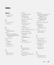
..., 107 beep codes, 26 bezel installing, 47 boot drive configuring, 54 boot sequence, 32 C cables drive interface, 47 drive power, 48 CD drive troubleshooting, 102 CD-ROM drive. See optical drive checking equipment, 92 configuring boot drive, 54 connecting external devices, 14 connectors system board, 118 console redirection screen, 35 contacting Dell, 126 control panel assembly installing, 87 cooling fans troubleshooting, 99 cover installing, 47 CPU setup options, 33 D damaged systems troubleshooting, 97 Dell contacting, 126 Dell PowerEdge Diagnostics using, 111 diagnostics advanced testing...
..., 107 beep codes, 26 bezel installing, 47 boot drive configuring, 54 boot sequence, 32 C cables drive interface, 47 drive power, 48 CD drive troubleshooting, 102 CD-ROM drive. See optical drive checking equipment, 92 configuring boot drive, 54 connecting external devices, 14 connectors system board, 118 console redirection screen, 35 contacting Dell, 126 control panel assembly installing, 87 cooling fans troubleshooting, 99 cover installing, 47 CPU setup options, 33 D damaged systems troubleshooting, 97 Dell contacting, 126 Dell PowerEdge Diagnostics using, 111 diagnostics advanced testing...

Hardware Owner's Manual (PDF)
Page 157
...diskette drive, 48 expansion card, 73 front system fan, 66 front-panel drive inserts, 45 removing (continued) hard drive, 54 memory, 78 processor, 79 system board, 87 removing and replacing battery, 83 S safety, 91 SAS controller daughter card troubleshooting, 107 SAS RAID controller daughter card troubleshooting, 107 SCSI backplane installing, 61 securing your system, 38 serial I/O device troubleshooting, 94 setup password assigning, 39 changing, 40 using, 39 setup password enabled working with, 40 setup password features, 37 startup accessing system features, 10 support contacting Dell, 126...
...diskette drive, 48 expansion card, 73 front system fan, 66 front-panel drive inserts, 45 removing (continued) hard drive, 54 memory, 78 processor, 79 system board, 87 removing and replacing battery, 83 S safety, 91 SAS controller daughter card troubleshooting, 107 SAS RAID controller daughter card troubleshooting, 107 SCSI backplane installing, 61 securing your system, 38 serial I/O device troubleshooting, 94 setup password assigning, 39 changing, 40 using, 39 setup password enabled working with, 40 setup password features, 37 startup accessing system features, 10 support contacting Dell, 126...


