EMC PowerSwitch S5200F-ON Series Setup Guide
Page 3
... 8 Unpack...8 Ground cable...9 Rack or cabinet installation...9 One-half U front-rack installation...10 One-half U switch installation...11 One-half U switch removal...12 One U ReadyRails installation...12 1U Tool-less mount installation...13 Two-post flush-mount installation...14 Two-post center-...mount installation...14 Four-post threaded installation...15 S5200F-ON Series switch installation...16 Two U four-post rack assembly...18 Four-post rack mount...18 DC power connections...19 S5212F-ON only DC power ...
... 8 Unpack...8 Ground cable...9 Rack or cabinet installation...9 One-half U front-rack installation...10 One-half U switch installation...11 One-half U switch removal...12 One U ReadyRails installation...12 1U Tool-less mount installation...13 Two-post flush-mount installation...14 Two-post center-...mount installation...14 Four-post threaded installation...15 S5200F-ON Series switch installation...16 Two U four-post rack assembly...18 Four-post rack mount...18 DC power connections...19 S5212F-ON only DC power ...

EMC PowerSwitch S5200F-ON Series Setup Guide
Page 4
...documents For more information about the S5200F-ON Series (S5232F-ON, S5248F-ON, S5296F-ON, S5224F-ON, and S5212F-ON) switches, see the following documents. • Dell EMC SmartFabric OS10 Release Notes • Dell EMC SmartFabric OS10 User Guide • Delll EMC PowerSwitch S5200F-ON Series Installation Guide.... • Marketing model S5224F-ON is represented by the regulatory model E21W and the regulatory type E21W003. • Marketing model S5296F-ON is represented by the regulatory model E29W and the regulatory type E29W001. Avoid exposure to a power source. Disconnect both power ...
...documents For more information about the S5200F-ON Series (S5232F-ON, S5248F-ON, S5296F-ON, S5224F-ON, and S5212F-ON) switches, see the following documents. • Dell EMC SmartFabric OS10 Release Notes • Dell EMC SmartFabric OS10 User Guide • Delll EMC PowerSwitch S5200F-ON Series Installation Guide.... • Marketing model S5224F-ON is represented by the regulatory model E21W and the regulatory type E21W003. • Marketing model S5296F-ON is represented by the regulatory model E29W and the regulatory type E29W001. Avoid exposure to a power source. Disconnect both power ...
EMC PowerSwitch S5200F-ON Series Setup Guide
Page 6
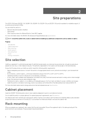
...the area where you prepare your area uses. 2 Site preparations The 5200F-ON Series (S5232F-ON, S5248F-ON, S5296F-ON, S5224F-ON, and S5212F-ON) switch is suitable for the location controls access to the restricted area. Topics: • Site selection • Cabinet ...power source. The authority responsible for installation as cables or optics. Airflow must be permanent. 6 Site preparations NOTE: Install the switch into a rack or cabinet before installing any additional components such as part of security. For cabinet placement requirements, see Specifications. You...
...the area where you prepare your area uses. 2 Site preparations The 5200F-ON Series (S5232F-ON, S5248F-ON, S5296F-ON, S5224F-ON, and S5212F-ON) switch is suitable for the location controls access to the restricted area. Topics: • Site selection • Cabinet ...power source. The authority responsible for installation as cables or optics. Airflow must be permanent. 6 Site preparations NOTE: Install the switch into a rack or cabinet before installing any additional components such as part of security. For cabinet placement requirements, see Specifications. You...
EMC PowerSwitch S5200F-ON Series Setup Guide
Page 7
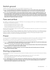
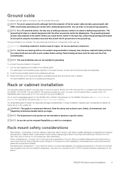
Switch ground Dell EMC recommends grounding your S5200F-ON Series switch and components immediately, properly store the switch and all power cables are mishandled. The ground lug bracket screws ship attached to the ground lug. The DC-powered switch ships with fan airflow from the PSU to the I/O-reverse Be ...part of the AC power cable provides a ground path, Dell EMC recommends grounding your site's ventilation. Use a single type of clearance around the exhaust vents. When you service the power supply slots. Power To connect the switch to the PSU-normal • DC fan unit with the...
Switch ground Dell EMC recommends grounding your S5200F-ON Series switch and components immediately, properly store the switch and all power cables are mishandled. The ground lug bracket screws ship attached to the ground lug. The DC-powered switch ships with fan airflow from the PSU to the I/O-reverse Be ...part of the AC power cable provides a ground path, Dell EMC recommends grounding your site's ventilation. Use a single type of clearance around the exhaust vents. When you service the power supply slots. Power To connect the switch to the PSU-normal • DC fan unit with the...
EMC PowerSwitch S5200F-ON Series Setup Guide
Page 8
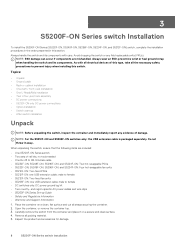
...; S5212F-ON: Two fixed fan units • S5296F-ON: one USB extension cable; Carefully remove the switch from the container and place it away. Inspect the product and accessories for damage. 8 S5200F-ON Series switch Installation Always wear an ESD-preventive wrist or heel ...8226; After switch installation Unpack NOTE: Before unpacking the switch, inspect the container and immediately report any field replaceable units (FRUs). Always handle the switch and its components. Avoid dropping the switch or any evidence of damage. NOTE: For the S5212F-ON and S5296F-ON switches only: the...
...; S5212F-ON: Two fixed fan units • S5296F-ON: one USB extension cable; Carefully remove the switch from the container and place it away. Inspect the product and accessories for damage. 8 S5200F-ON Series switch Installation Always wear an ESD-preventive wrist or heel ...8226; After switch installation Unpack NOTE: Before unpacking the switch, inspect the container and immediately report any field replaceable units (FRUs). Always handle the switch and its components. Avoid dropping the switch or any evidence of damage. NOTE: For the S5212F-ON and S5296F-ON switches only: the...
EMC PowerSwitch S5200F-ON Series Setup Guide
Page 9
.... Rack mount safety considerations • Rack loading-Overloading or uneven loading of the AC power cable provides a ground path, Dell EMC recommends grounding your switch is a condensed reference. When you begin installation, separate each rail assembly by sliding the inside the shipping box. Use care...conductor of racks may either place the switch on the unit. NOTE: For a DC-powered switch, the only way to safely ground your switch with the other end of copper. The ground cable is provided for the S5296F-ON or S5212F-ON switches. Use the shortest cable route allowable....
.... Rack mount safety considerations • Rack loading-Overloading or uneven loading of the AC power cable provides a ground path, Dell EMC recommends grounding your switch is a condensed reference. When you begin installation, separate each rail assembly by sliding the inside the shipping box. Use care...conductor of racks may either place the switch on the unit. NOTE: For a DC-powered switch, the only way to safely ground your switch with the other end of copper. The ground cable is provided for the S5296F-ON or S5212F-ON switches. Use the shortest cable route allowable....
EMC PowerSwitch S5200F-ON Series Setup Guide
Page 10
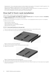
... and rack mounting rail 3. Rackmount screws are not included. 6. The dual-tray mounting rails ship with the dual tray, not with the switch. Remove the dual tray and the rails from the front. Figure 2. Repeat with the other than the direct connections to the supply connections ... You must supply eight rackmount screws for this installation. Install the dual tray inside the four-post rack. To install the S5296F-ON switch, see One U ReadyRails installation. Slide the rail back until it . • Reliable earthing-Maintain reliable earthing of rack-mounted equipment. Figure...
... and rack mounting rail 3. Rackmount screws are not included. 6. The dual-tray mounting rails ship with the dual tray, not with the switch. Remove the dual tray and the rails from the front. Figure 2. Repeat with the other than the direct connections to the supply connections ... You must supply eight rackmount screws for this installation. Install the dual tray inside the four-post rack. To install the S5296F-ON switch, see One U ReadyRails installation. Slide the rail back until it . • Reliable earthing-Maintain reliable earthing of rack-mounted equipment. Figure...
EMC PowerSwitch S5200F-ON Series Setup Guide
Page 11
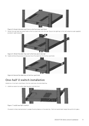
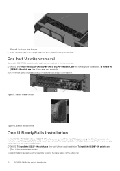
...tray into place. Secure the dual-tray in the four-post rack One-half U switch installation Install one or two half-U switches in the four-post rack-mounted dual tray. 1. Attach the rear dual-tray switch rails to the rack using two user-supplied screws for each rack post. Attach the... dual-tray rear to the four-post rack front 7. Figure 7. The front switch latch snaps the switch into the four-post rack. Figure 4. Attach the dual-tray front to the four-post rack rear 8. Secure the dual tray to ...
...tray into place. Secure the dual-tray in the four-post rack One-half U switch installation Install one or two half-U switches in the four-post rack-mounted dual tray. 1. Attach the rear dual-tray switch rails to the rack using two user-supplied screws for each rack post. Attach the... dual-tray rear to the four-post rack front 7. Figure 7. The front switch latch snaps the switch into the four-post rack. Figure 4. Attach the dual-tray front to the four-post rack rear 8. Secure the dual tray to ...
EMC PowerSwitch S5200F-ON Series Setup Guide
Page 12
...-post center mount, or four-post threaded mount. To install the S5296F-ON switch, see One U ReadyRails installation. NOTE: To remove the S5232F-ON, S5248F-ON, or S5224F-ON switch, see Two U four-post rack assembly. Figure 9. Switch release arrow One U ReadyRails installation For the S5248F-ON, S5232F-ON... rack assembly. Insert the second switch in the front switch latches according to the latch arrows and pull out the switch. One-half U switch removal Remove the S5212F-ON switch from the dual tray from the front of the four-post rack. To remove the S5296F-ON switch, see One-half U front-...
...-post center mount, or four-post threaded mount. To install the S5296F-ON switch, see One U ReadyRails installation. NOTE: To remove the S5232F-ON, S5248F-ON, or S5224F-ON switch, see Two U four-post rack assembly. Figure 9. Switch release arrow One U ReadyRails installation For the S5248F-ON, S5232F-ON... rack assembly. Insert the second switch in the front switch latches according to the latch arrows and pull out the switch. One-half U switch removal Remove the S5212F-ON switch from the dual tray from the front of the four-post rack. To remove the S5296F-ON switch, see One-half U front-...
EMC PowerSwitch S5200F-ON Series Setup Guide
Page 13
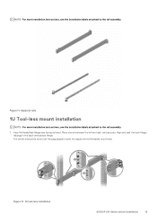
... vertical posts. NOTE: For more installation instructions, see the installation labels attached to the rail assembly. 1. Figure 12. 1U tool-less installation S5200F-ON Series switch Installation 13 The center extractions show how the pegs appear in the back vertical post flange. Figure 11. Separate rails 1U Tool-less mount installation...
... vertical posts. NOTE: For more installation instructions, see the installation labels attached to the rail assembly. 1. Figure 12. 1U tool-less installation S5200F-ON Series switch Installation 13 The center extractions show how the pegs appear in the back vertical post flange. Figure 11. Separate rails 1U Tool-less mount installation...
EMC PowerSwitch S5200F-ON Series Setup Guide
Page 14
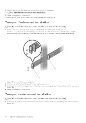
... the rails click into place and secure the bracket to the post flange with two user-supplied screws, item 1. 14 S5200F-ON Series switch Installation Repeat this procedure for future rack requirements. For this procedure for the second rail. Align and seat the front flange pegs in the... holes on the switch side of the rail and remove each latch casting, use a Torx screwdriver. Repeat this configuration, remove the latch castings from each front flange...
... the rails click into place and secure the bracket to the post flange with two user-supplied screws, item 1. 14 S5200F-ON Series switch Installation Repeat this procedure for future rack requirements. For this procedure for the second rail. Align and seat the front flange pegs in the... holes on the switch side of the rail and remove each latch casting, use a Torx screwdriver. Repeat this configuration, remove the latch castings from each front flange...
EMC PowerSwitch S5200F-ON Series Setup Guide
Page 15
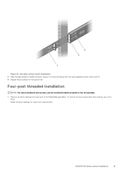
... to the post flange with two user-supplied screws, items 2 and 3. 3. Remove the latch castings from each latch casting, use a Torx driver. S5200F-ON Series switch Installation 15 Secure it to the rail assembly. 1. To remove the two screws each end of the ReadyRails assemblies. Retain the latch castings for the...
... to the post flange with two user-supplied screws, items 2 and 3. 3. Remove the latch castings from each latch casting, use a Torx driver. S5200F-ON Series switch Installation 15 Secure it to the rail assembly. 1. To remove the two screws each end of the ReadyRails assemblies. Retain the latch castings for the...
EMC PowerSwitch S5200F-ON Series Setup Guide
Page 16
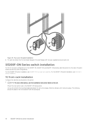
NOTE: For more information, see S5296F-ON four-post rack assembly. Attach the inner switch rails to the switch. 1. For the S5296F-ON switch installation, see the installation instruction labels on the rail. For the S5212F-ON switch installation, see One-half U switch installation. 1U front-rack installation Configure the rails that are attached to the S5200F-ON...
NOTE: For more information, see S5296F-ON four-post rack assembly. Attach the inner switch rails to the switch. 1. For the S5296F-ON switch installation, see the installation instruction labels on the rail. For the S5212F-ON switch installation, see One-half U switch installation. 1U front-rack installation Configure the rails that are attached to the S5200F-ON...
EMC PowerSwitch S5200F-ON Series Setup Guide
Page 17
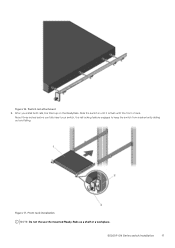
S5200F-ON Series switch Installation 17 Front rack installation NOTE: Do not the use the mounted Ready-Rails as a shelf or a workplace. Slide the switch in until it is flush with the front of rack. About three inches before you install both rails, line them up on the ReadyRails. Switch rail attachment 2. Figure 16. After you fully insert your switch, the rail locking feature engages to keep the switch from inadvertently sliding out and falling. Figure 17.
S5200F-ON Series switch Installation 17 Front rack installation NOTE: Do not the use the mounted Ready-Rails as a shelf or a workplace. Slide the switch in until it is flush with the front of rack. About three inches before you install both rails, line them up on the ReadyRails. Switch rail attachment 2. Figure 16. After you fully insert your switch, the rail locking feature engages to keep the switch from inadvertently sliding out and falling. Figure 17.
EMC PowerSwitch S5200F-ON Series Setup Guide
Page 18
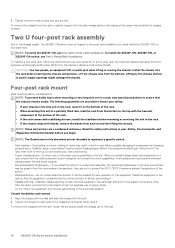
...Lift the chassis only from the rack, loosen the screws and slide the chassis out of the rack, then work to the chassis weight, the S5296F-ON switch does not support a two-post rack installation; 3. NOTE: To install the S5212F-ON, see One U ReadyRails installation. When you must install the... S5296F-ON in the rack so that the equipment constantly has the correct amount of airflow surrounding it at the same time and slide the chassis forward. Pay particular attention to the top with the heaviest component at the bottom of the rack. 18 S5200F-ON Series switch Installation ...
...Lift the chassis only from the rack, loosen the screws and slide the chassis out of the rack, then work to the chassis weight, the S5296F-ON switch does not support a two-post rack installation; 3. NOTE: To install the S5212F-ON, see One U ReadyRails installation. When you must install the... S5296F-ON in the rack so that the equipment constantly has the correct amount of airflow surrounding it at the same time and slide the chassis forward. Pay particular attention to the top with the heaviest component at the bottom of the rack. 18 S5200F-ON Series switch Installation ...
EMC PowerSwitch S5200F-ON Series Setup Guide
Page 19
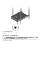
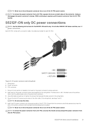
One set containing a prewired (3-inch 8AWG) power supply connector and a four-screw wiring block. Main screw DC power connections NOTE: Use the following instructions for all S5200F-ON Series switches except for each DC PSU. To connect DC power to restrict front-back movement of the switch. 2. S5200F-ON Series switch Installation 19 Each DC powered system comes with a set is provided for the S5212F-ON switch. Extra screws to the S5212F-ON switch, see S5212F-ON only DC power connections. S5296F-ON installation 1. Figure 18.
One set containing a prewired (3-inch 8AWG) power supply connector and a four-screw wiring block. Main screw DC power connections NOTE: Use the following instructions for all S5200F-ON Series switches except for each DC PSU. To connect DC power to restrict front-back movement of the switch. 2. S5200F-ON Series switch Installation 19 Each DC powered system comes with a set is provided for the S5212F-ON switch. Extra screws to the S5212F-ON switch, see S5212F-ON only DC power connections. S5296F-ON installation 1. Figure 18.
EMC PowerSwitch S5200F-ON Series Setup Guide
Page 20
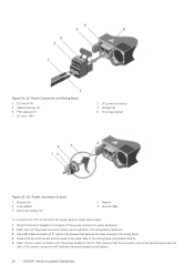
... seat and you hear the click of the wiring block (See steps 1 and 3). 5. Ensure that secures the bare wires into place. 20 S5200F-ON Series switch Installation DC Power Connector and Wiring Block 1. Ground cable To connect a DC PSU to the other side of the power connector's left and right levered...
... seat and you hear the click of the wiring block (See steps 1 and 3). 5. Ensure that secures the bare wires into place. 20 S5200F-ON Series switch Installation DC Power Connector and Wiring Block 1. Ground cable To connect a DC PSU to the other side of the power connector's left and right levered...
EMC PowerSwitch S5200F-ON Series Setup Guide
Page 21
...connections. Insert each of the connector. DC power connector and wiring block 1. Wiring block 2. Use a flat-blade screwdriver to the other S5200F-ON Series switches, see steps 1 and 3. NOTE: To remove the power connector from a DC PSU, unscrew the thumb screws and pull the power connector from a DC... 1. The blue wire is -48V, the black wire is the positive return, and the yellow/green wire is provided for the S5212F-ON switch only. NOTE: Do not cross the wires. 5. Insert the DC power connector into the power socket of the power connector's left and right...
...connections. Insert each of the connector. DC power connector and wiring block 1. Wiring block 2. Use a flat-blade screwdriver to the other S5200F-ON Series switches, see steps 1 and 3. NOTE: To remove the power connector from a DC PSU, unscrew the thumb screws and pull the power connector from a DC... 1. The blue wire is -48V, the black wire is the positive return, and the yellow/green wire is provided for the S5212F-ON switch only. NOTE: Do not cross the wires. 5. Insert the DC power connector into the power socket of the power connector's left and right...
EMC PowerSwitch S5200F-ON Series Setup Guide
Page 22
...may cause eye damage. 1. Before pulling the release tab, you use sufficient overcurrent protection devices. Reinspect your switch before you are using third-party software, see switch documentation at www.dell.com/support. • If you turn it may need to gently push the optic into the end of... prevents it from the port, pull the release tab firmly and steadily. After switch installation After you have securely installed and powered on the S5200F-ON Series switch: • If you are using Dell EMC software, see ONIE documentation at high speed. Never look directly into the ...
...may cause eye damage. 1. Before pulling the release tab, you use sufficient overcurrent protection devices. Reinspect your switch before you are using third-party software, see switch documentation at www.dell.com/support. • If you turn it may need to gently push the optic into the end of... prevents it from the port, pull the release tab firmly and steadily. After switch installation After you have securely installed and powered on the S5200F-ON Series switch: • If you are using Dell EMC software, see ONIE documentation at high speed. Never look directly into the ...
EMC PowerSwitch S5200F-ON Series Setup Guide
Page 23
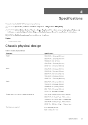
... inches (43.6 mm) S5212F-ON: 1.72 inches (43.6 mm) S5232F-ON: 17.1 inches (434 mm) S5248F-ON: 17.1 inches (434 mm) S5296F-ON: 16.6 inches (422 mm) S5224F-ON: 17.1 inches (434 mm) S5212F-ON: 7.87 inches (199.8 mm) S5232F-ON: 18.1 inches ...(460 mm) S5248F-ON: 18.1 inches (460 mm) S5296F-ON: 20.1 inches (511 mm) S5224F-ON: 18.1 inches (460 mm) S5212F-ON: 16 inches (406.4 mm) S5232F-ON: 21.6 lbs ... with same or equivalent type of battery. 4 Specifications This section lists the S5200F-ON Series switch specifications.
... inches (43.6 mm) S5212F-ON: 1.72 inches (43.6 mm) S5232F-ON: 17.1 inches (434 mm) S5248F-ON: 17.1 inches (434 mm) S5296F-ON: 16.6 inches (422 mm) S5224F-ON: 17.1 inches (434 mm) S5212F-ON: 7.87 inches (199.8 mm) S5232F-ON: 18.1 inches ...(460 mm) S5248F-ON: 18.1 inches (460 mm) S5296F-ON: 20.1 inches (511 mm) S5224F-ON: 18.1 inches (460 mm) S5212F-ON: 16 inches (406.4 mm) S5232F-ON: 21.6 lbs ... with same or equivalent type of battery. 4 Specifications This section lists the S5200F-ON Series switch specifications.


