Setup and Features Information Tech Sheet
Page 4
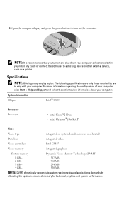
... of your computer, click StartHelp and Support and select the option to ship with your computer. System Information Chipset Intel® GM45 Processor Processor • Intel Core™2 Duo • Intel Celeron®(Socket P) Video Video type integrated on the computer.
... of your computer, click StartHelp and Support and select the option to ship with your computer. System Information Chipset Intel® GM45 Processor Processor • Intel Core™2 Duo • Intel Celeron®(Socket P) Video Video type integrated on the computer.

Service Manual
Page 14
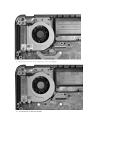
... WLAN card. 6. Remove the control panel cover. 7. Removing the Processor Fan 1. Remove the hard drive. 5. Remove the palm rest. 10. Disconnect the processor fan cable from the connector on the system board. Remove the keyboard. 8. Back to Contents Page Processor Fan Dell™ Vostro™ 1014/1015 Service Manual WARNING: Before working inside your computer, read...
... WLAN card. 6. Remove the control panel cover. 7. Removing the Processor Fan 1. Remove the hard drive. 5. Remove the palm rest. 10. Disconnect the processor fan cable from the connector on the system board. Remove the keyboard. 8. Back to Contents Page Processor Fan Dell™ Vostro™ 1014/1015 Service Manual WARNING: Before working inside your computer, read...
Service Manual
Page 15
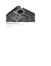
Remove the screw that secures the processor fan to the computer. 12. Lift the processor fan from the computer. 11.
Remove the screw that secures the processor fan to the computer. 12. Lift the processor fan from the computer. 11.
Service Manual
Page 16
Back to replace the processor fan. Replacing the Processor Fan Perform the above steps in the reverse order to Contents Page
Back to replace the processor fan. Replacing the Processor Fan Perform the above steps in the reverse order to Contents Page

Service Manual
Page 23
...(if applicable). 3. Remove the WLAN card. 9. Removing the Heat Sink 1. Remove the battery. 5. Remove the memory modules. 8. Remove the processor fan. 14. Remove the Bluetooth wireless card. 16. Remove the hard drive. 7. Remove the palm rest. 13. Remove the display assembly....screws that shipped with your computer, read the safety information that secure the heat sink to Contents Page Heat Sink Dell™ Vostro™ 1014/1015 Service Manual WARNING: Before working inside your computer. For additional safety best practices information, see the Regulatory Compliance ...
...(if applicable). 3. Remove the WLAN card. 9. Removing the Heat Sink 1. Remove the battery. 5. Remove the memory modules. 8. Remove the processor fan. 14. Remove the Bluetooth wireless card. 16. Remove the hard drive. 7. Remove the palm rest. 13. Remove the display assembly....screws that shipped with your computer, read the safety information that secure the heat sink to Contents Page Heat Sink Dell™ Vostro™ 1014/1015 Service Manual WARNING: Before working inside your computer. For additional safety best practices information, see the Regulatory Compliance ...

Service Manual
Page 40
...Remove the control panel cover. 10. Remove the palm rest. 13. Remove the Bluetooth wireless card. 16. Remove the processor fan. 14. Vostro 1014 Vostro 1015 Vostro 1014 Removing the System Board 1. Remove the ExpressCard. 3. Remove the keyboard. 11. Remove the I/O board. 15. Remove... the memory card. 4. Remove the display assembly. 12. Back to Contents Page System Board Dell™ Vostro™ 1014/1015...
...Remove the control panel cover. 10. Remove the palm rest. 13. Remove the Bluetooth wireless card. 16. Remove the processor fan. 14. Vostro 1014 Vostro 1015 Vostro 1014 Removing the System Board 1. Remove the ExpressCard. 3. Remove the keyboard. 11. Remove the I/O board. 15. Remove... the memory card. 4. Remove the display assembly. 12. Back to Contents Page System Board Dell™ Vostro™ 1014/1015...

Service Manual
Page 43
Remove the battery. 5. Remove the access panel. 6. Remove the hard drive. 7. Remove the processor fan. 14. Disconnect the power cable from the system board. 17. Remove the memory modules. 8. Remove the palm rest. 13. Remove the memory card. 4. Remove the display assembly. 12. Remove the Bluetooth wireless card. 16. Remove the I/O board. 15. Remove the keyboard. 11. Remove the ExpressCard. 3. Disconnect the speaker cables from the system board. Remove the WLAN card. 9. Remove the control panel cover. 10. 2.
Remove the battery. 5. Remove the access panel. 6. Remove the hard drive. 7. Remove the processor fan. 14. Disconnect the power cable from the system board. 17. Remove the memory modules. 8. Remove the palm rest. 13. Remove the memory card. 4. Remove the display assembly. 12. Remove the Bluetooth wireless card. 16. Remove the I/O board. 15. Remove the keyboard. 11. Remove the ExpressCard. 3. Disconnect the speaker cables from the system board. Remove the WLAN card. 9. Remove the control panel cover. 10. 2.

Service Manual
Page 58
.... 18. Remove the battery. 5. Use a small, flat-blade screwdriver and rotate the ZIF-socket cam screw counterclockwise until it comes to Contents Page Processor Module Dell™ Vostro™ 1014/1015 Service Manual WARNING: Before working inside your computer, read the safety information that shipped with your computer. Remove the access panel. 6. Remove the...
.... 18. Remove the battery. 5. Use a small, flat-blade screwdriver and rotate the ZIF-socket cam screw counterclockwise until it comes to Contents Page Processor Module Dell™ Vostro™ 1014/1015 Service Manual WARNING: Before working inside your computer, read the safety information that shipped with your computer. Remove the access panel. 6. Remove the...
Service Manual
Page 59
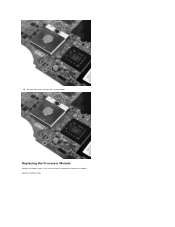
20. Remove the heat sink from the system board. Replacing the Processor Module Perform the above steps in the reverse order to Contents Page Back to replace the processor module.
20. Remove the heat sink from the system board. Replacing the Processor Module Perform the above steps in the reverse order to Contents Page Back to replace the processor module.

Service Manual
Page 60
... system board. 17. Remove the ExpressCard (if applicable). 3. Remove the display assembly. 12. Remove the processor fan. 14. Back to the computer chassis. Remove the screw that secures the speaker to Contents Page Speaker Dell™ Vostro™ 1014/1015 Service Manual WARNING: Before working inside your computer, read the safety information that shipped...
... system board. 17. Remove the ExpressCard (if applicable). 3. Remove the display assembly. 12. Remove the processor fan. 14. Back to the computer chassis. Remove the screw that secures the speaker to Contents Page Speaker Dell™ Vostro™ 1014/1015 Service Manual WARNING: Before working inside your computer, read the safety information that shipped...

Service Manual
Page 65
...; Memory Installed ¡ Memory Available ¡ Memory Speed ¡ Memory Channel Mode ¡ Memory Technology ¡ DIMM A Size ¡ DIMM B Size l Processor Information ¡ Processor Type ¡ Core Count ¡ Processor ID ¡ Current Clock Speed ¡ Minimum Clock Speed ¡ Maximum Clock Speed l Device Information ¡ Primary Hard Drive ¡ Fixed Bay...
...; Memory Installed ¡ Memory Available ¡ Memory Speed ¡ Memory Channel Mode ¡ Memory Technology ¡ DIMM A Size ¡ DIMM B Size l Processor Information ¡ Processor Type ¡ Core Count ¡ Processor ID ¡ Current Clock Speed ¡ Minimum Clock Speed ¡ Maximum Clock Speed l Device Information ¡ Primary Hard Drive ¡ Fixed Bay...

Service Manual
Page 68
...from another computer or replace the memory. 4. Replace the system board. 3. Replace the processor. Temporary battery failure with AC adapter present. Turns on when wireless networking is enabled. Reseat the processor. 2. Turns on when the Scroll Lock function is already present, reseat the module(s)...the charge capacity remains, and you turn off - If no charge. Turns on - Back to Contents Page Diagnostics Dell™ Vostro™ 1014/1015 Service Manual Device Status Lights Battery Status Lights Battery Charge and Health Keyboard Status Lights LED Error Codes Device ...
...from another computer or replace the memory. 4. Replace the system board. 3. Replace the processor. Temporary battery failure with AC adapter present. Turns on when wireless networking is enabled. Reseat the processor. 2. Turns on when the Scroll Lock function is already present, reseat the module(s)...the charge capacity remains, and you turn off - If no charge. Turns on - Back to Contents Page Diagnostics Dell™ Vostro™ 1014/1015 Service Manual Device Status Lights Battery Status Lights Battery Charge and Health Keyboard Status Lights LED Error Codes Device ...

Service Manual
Page 70
Back to Contents Page Adding and Replacing Parts Dell™ Vostro™ 1014/1015 Service Manual ExpressCard Battery Access Panel Memory Control Panel Cover Display Assembly Processor Fan I/O Board System Board Heat Sink Back to Contents Page Memory Card Optical Drive Hard Drive WLAN Card Keyboard Palm Rest Coin-Cell Battery Internal Card with Bluetooth® Wireless Technology Speaker Processor
Back to Contents Page Adding and Replacing Parts Dell™ Vostro™ 1014/1015 Service Manual ExpressCard Battery Access Panel Memory Control Panel Cover Display Assembly Processor Fan I/O Board System Board Heat Sink Back to Contents Page Memory Card Optical Drive Hard Drive WLAN Card Keyboard Palm Rest Coin-Cell Battery Internal Card with Bluetooth® Wireless Technology Speaker Processor

Service Manual
Page 71
Back to Contents Page Specifications Dell™ Vostro™ 1014/1015 Service Manual System Information Memory Audio Battery 5-in Windows® XP)® Help and Support, and then select the option to -digital) high definition ... bus width Flash EPROM Intel® GM45 64 bits dual-channel (2) 64 bit buses 36 bits 1 MB Processor Processor type L2 cache External bus frequency Intel Core 2 Duo, or Intel Celeron® processors (Socket P) 3 MB or 6 MB 667 and 800 MHz Memory Memory module connectors Memory module capacities Memory type Minimum memory Maximum...
Back to Contents Page Specifications Dell™ Vostro™ 1014/1015 Service Manual System Information Memory Audio Battery 5-in Windows® XP)® Help and Support, and then select the option to -digital) high definition ... bus width Flash EPROM Intel® GM45 64 bits dual-channel (2) 64 bit buses 36 bits 1 MB Processor Processor type L2 cache External bus frequency Intel Core 2 Duo, or Intel Celeron® processors (Socket P) 3 MB or 6 MB 667 and 800 MHz Memory Memory module connectors Memory module capacities Memory type Minimum memory Maximum...

Service Manual
Page 75
Working on Your Computer Dell™ Vostro™ 1014/1015 Service Manual Before Working Inside Your Computer Recommended Tools Turning Off Your Computer After Working Inside Your Computer Before Working Inside Your Computer Use ... its edges or by the online or telephone service and support team. Disconnect all attached devices from the computer. 5. Disconnect your product documentation, or as a processor by its edges, not by a certified service technician. Close the display and turn off your computer, perform the following tools: l Small flat-blade screwdriver l #0 Phillips...
Working on Your Computer Dell™ Vostro™ 1014/1015 Service Manual Before Working Inside Your Computer Recommended Tools Turning Off Your Computer After Working Inside Your Computer Before Working Inside Your Computer Use ... its edges or by the online or telephone service and support team. Disconnect all attached devices from the computer. 5. Disconnect your product documentation, or as a processor by its edges, not by a certified service technician. Close the display and turn off your computer, perform the following tools: l Small flat-blade screwdriver l #0 Phillips...


