
Setup and Features Information Tech Sheet
Page 1
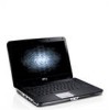
About Warnings WARNING: A WARNING indicates a potential for property damage, personal injury, or death. Dell™ Vostro™ 1014/1015 Setup and Features Information Tech Sheet Front View 123 4 17 16 15 14 13 1 microphone (optional) 3 camera (optional) 5 keyboard status lights November 2010 5 6 9 87 12 11 10 2 camera light (optional) 4 display 6 power button Models: PP38L and PP37L
About Warnings WARNING: A WARNING indicates a potential for property damage, personal injury, or death. Dell™ Vostro™ 1014/1015 Setup and Features Information Tech Sheet Front View 123 4 17 16 15 14 13 1 microphone (optional) 3 camera (optional) 5 keyboard status lights November 2010 5 6 9 87 12 11 10 2 camera light (optional) 4 display 6 power button Models: PP38L and PP37L

Service Manual
Page 1
... to hardware or loss of data if instructions are trademarks of Dell Inc. Adobe, the Adobe logo, and Adobe Flash Player are not followed. is a registered trademark owned by Dell under license; Dell™ Vostro™ 1014/1015 Service Manual Working on Your Computer Adding and Replacing Parts Specifications Diagnostics System Setup Notes, Cautions, and Warnings NOTE: A NOTE indicates important information that helps you purchased a Dell™ n Series...
... to hardware or loss of data if instructions are trademarks of Dell Inc. Adobe, the Adobe logo, and Adobe Flash Player are not followed. is a registered trademark owned by Dell under license; Dell™ Vostro™ 1014/1015 Service Manual Working on Your Computer Adding and Replacing Parts Specifications Diagnostics System Setup Notes, Cautions, and Warnings NOTE: A NOTE indicates important information that helps you purchased a Dell™ n Series...

Service Manual
Page 6
..., see the Regulatory Compliance Homepage at www.dell.com/regulatory_compliance. Follow the procedures in Before Working Inside Your Computer. 2. Remove the WLAN card. 6. Remove the keyboard. 8. Back to Contents Page Internal Card With Bluetooth® Wireless Technology Dell™ Vostro™ 1014/1015 Service Manual WARNING: Before working inside your computer, read the safety information that shipped with your computer. Remove the battery. 3. Remove the hard drive. 5. Remove the display assembly. 9. Remove the access panel. 4. Removing the Bluetooth Wireless Card 1.
..., see the Regulatory Compliance Homepage at www.dell.com/regulatory_compliance. Follow the procedures in Before Working Inside Your Computer. 2. Remove the WLAN card. 6. Remove the keyboard. 8. Back to Contents Page Internal Card With Bluetooth® Wireless Technology Dell™ Vostro™ 1014/1015 Service Manual WARNING: Before working inside your computer, read the safety information that shipped with your computer. Remove the battery. 3. Remove the hard drive. 5. Remove the display assembly. 9. Remove the access panel. 4. Removing the Bluetooth Wireless Card 1.

Service Manual
Page 8
... safety best practices information, see the Regulatory Compliance Homepage at www.dell.com/regulatory_compliance. Remove the WLAN card. 6. Remove the keyboard. 8. Removing the Coin-Cell Battery 1. Remove the hard drive. 5. Remove the palm rest. 10. Remove the access panel. 4. Remove the display assembly. 9. Remove the control panel cover. 7. Back to Contents Page Coin-Cell Battery Dell™ Vostro™ 1014/1015 Service Manual WARNING: Before working inside your computer, read the safety information that shipped with your...
... safety best practices information, see the Regulatory Compliance Homepage at www.dell.com/regulatory_compliance. Remove the WLAN card. 6. Remove the keyboard. 8. Removing the Coin-Cell Battery 1. Remove the hard drive. 5. Remove the palm rest. 10. Remove the access panel. 4. Remove the display assembly. 9. Remove the control panel cover. 7. Back to Contents Page Coin-Cell Battery Dell™ Vostro™ 1014/1015 Service Manual WARNING: Before working inside your computer, read the safety information that shipped with your...

Service Manual
Page 14
Follow the procedures in Before Working Inside Your Computer. 2. Remove the display assembly. 9. Disconnect the processor fan cable from the connector on the system board. Remove the battery. 3. Remove the keyboard. 8. Remove the access panel. 4. Removing the Processor Fan 1. Remove the WLAN card. 6. Remove the control panel cover. 7. Remove the hard drive. 5. Remove the palm rest. 10. Back to Contents Page Processor Fan Dell™ Vostro™ 1014/1015 Service Manual WARNING: Before working inside your computer, read the safety information that shipped...
Follow the procedures in Before Working Inside Your Computer. 2. Remove the display assembly. 9. Disconnect the processor fan cable from the connector on the system board. Remove the battery. 3. Remove the keyboard. 8. Remove the access panel. 4. Removing the Processor Fan 1. Remove the WLAN card. 6. Remove the control panel cover. 7. Remove the hard drive. 5. Remove the palm rest. 10. Back to Contents Page Processor Fan Dell™ Vostro™ 1014/1015 Service Manual WARNING: Before working inside your computer, read the safety information that shipped...

Service Manual
Page 23
...). 3. Remove the access panel. 6. Remove the memory modules. 8. Remove the Bluetooth wireless card. 16. Remove the display assembly. 12. Remove the I/O board. 15. Remove the keyboard. 11. Remove the palm rest. 13. For additional safety best practices information, see the Regulatory Compliance Homepage at www.dell.com/regulatory_compliance. Remove the WLAN card. 9. Remove the control panel cover. 10. Remove the system board and place the system board on a clean, dry surface. 17. Remove the hard drive. 7. Remove the processor fan. 14. Use the...
...). 3. Remove the access panel. 6. Remove the memory modules. 8. Remove the Bluetooth wireless card. 16. Remove the display assembly. 12. Remove the I/O board. 15. Remove the keyboard. 11. Remove the palm rest. 13. For additional safety best practices information, see the Regulatory Compliance Homepage at www.dell.com/regulatory_compliance. Remove the WLAN card. 9. Remove the control panel cover. 10. Remove the system board and place the system board on a clean, dry surface. 17. Remove the hard drive. 7. Remove the processor fan. 14. Use the...

Service Manual
Page 25
... the Regulatory Compliance Homepage at www.dell.com/regulatory_compliance. Removing the I /O Board Dell™ Vostro™ 1014/1015 Service Manual WARNING: Before working inside your computer. Remove the hard drive. 5. Remove the display assembly. 9. Remove the WLAN card. 6. Follow the procedures in Before Working Inside Your Computer. 2. Remove the keyboard. 8. Remove the control panel cover. 7. Back to the computer chassis. Remove the battery. 3. Remove the palm rest. 10. Remove the access panel. 4. Remove the two screws that shipped with your...
... the Regulatory Compliance Homepage at www.dell.com/regulatory_compliance. Removing the I /O Board Dell™ Vostro™ 1014/1015 Service Manual WARNING: Before working inside your computer. Remove the hard drive. 5. Remove the display assembly. 9. Remove the WLAN card. 6. Follow the procedures in Before Working Inside Your Computer. 2. Remove the keyboard. 8. Remove the control panel cover. 7. Back to the computer chassis. Remove the battery. 3. Remove the palm rest. 10. Remove the access panel. 4. Remove the two screws that shipped with your...

Service Manual
Page 30
... access panel. 4. Remove the control panel cover. 7. Remove the keyboard. 8. Remove the battery. 3. Disconnect the wireless cables. Back to Contents Page Display Dell™ Vostro™ 1014/1015 Service Manual WARNING: Before working inside your computer, read the safety information that shipped with your computer. Remove the hard drive. 5. Removing the Display Assembly Replacing the Display Assembly Removing the Display Bezel Replacing the Display Bezel Removing the LED Display Panel Replacing the LED Display Panel Removing the Display Camera Replacing the Display Camera...
... access panel. 4. Remove the control panel cover. 7. Remove the keyboard. 8. Remove the battery. 3. Disconnect the wireless cables. Back to Contents Page Display Dell™ Vostro™ 1014/1015 Service Manual WARNING: Before working inside your computer, read the safety information that shipped with your computer. Remove the hard drive. 5. Removing the Display Assembly Replacing the Display Assembly Removing the Display Bezel Replacing the Display Bezel Removing the LED Display Panel Replacing the LED Display Panel Removing the Display Camera Replacing the Display Camera...

Service Manual
Page 40
... System Board 1. Remove the battery. 5. Remove the WLAN card. 9. Disconnect the speaker cables from the system board. Remove the control panel cover. 10. Remove the display assembly. 12. Remove the Bluetooth wireless card. 16. Remove the ExpressCard. 3. Follow the procedures in Before Working Inside Your Computer. 2. Remove the processor fan. 14. Remove the memory card. 4. Remove the keyboard. 11. For additional safety best practices information, see the Regulatory Compliance Homepage at www.dell.com/regulatory_compliance. Remove the memory modules. 8. Remove the hard drive...
... System Board 1. Remove the battery. 5. Remove the WLAN card. 9. Disconnect the speaker cables from the system board. Remove the control panel cover. 10. Remove the display assembly. 12. Remove the Bluetooth wireless card. 16. Remove the ExpressCard. 3. Follow the procedures in Before Working Inside Your Computer. 2. Remove the processor fan. 14. Remove the memory card. 4. Remove the keyboard. 11. For additional safety best practices information, see the Regulatory Compliance Homepage at www.dell.com/regulatory_compliance. Remove the memory modules. 8. Remove the hard drive...

Service Manual
Page 43
Remove the WLAN card. 9. Remove the I/O board. 15. Remove the battery. 5. Remove the display assembly. 12. Disconnect the power cable from the system board. 17. Remove the keyboard. 11. Remove the palm rest. 13. Remove the access panel. 6. Remove the memory modules. 8. Remove the Bluetooth wireless card. 16. Disconnect the speaker cables from the system board. Remove the memory card. 4. Remove the hard drive. 7. Remove the processor fan. 14. Remove the ExpressCard. 3. 2. Remove the control panel cover. 10.
Remove the WLAN card. 9. Remove the I/O board. 15. Remove the battery. 5. Remove the display assembly. 12. Disconnect the power cable from the system board. 17. Remove the keyboard. 11. Remove the palm rest. 13. Remove the access panel. 6. Remove the memory modules. 8. Remove the Bluetooth wireless card. 16. Disconnect the speaker cables from the system board. Remove the memory card. 4. Remove the hard drive. 7. Remove the processor fan. 14. Remove the ExpressCard. 3. 2. Remove the control panel cover. 10.

Service Manual
Page 58
... Module 1. Remove the battery. 5. Remove the hard drive. 7. Remove the processor fan. 14. Remove the heat sink. 18. For additional safety best practices information, see the Regulatory Compliance Homepage at www.dell.com/regulatory_compliance. Remove the control panel cover. 10. Remove the Bluetooth wireless card. 16. Use a small, flat-blade screwdriver and rotate the ZIF-socket cam screw counterclockwise until it comes to Contents Page Processor Module Dell™ Vostro™ 1014/1015 Service Manual...
... Module 1. Remove the battery. 5. Remove the hard drive. 7. Remove the processor fan. 14. Remove the heat sink. 18. For additional safety best practices information, see the Regulatory Compliance Homepage at www.dell.com/regulatory_compliance. Remove the control panel cover. 10. Remove the Bluetooth wireless card. 16. Use a small, flat-blade screwdriver and rotate the ZIF-socket cam screw counterclockwise until it comes to Contents Page Processor Module Dell™ Vostro™ 1014/1015 Service Manual...

Service Manual
Page 60
... the ExpressCard (if applicable). 3. Remove the I/O board. 15. Remove the Bluetooth® wireless card. 16. Remove the system board. 17. Remove the control panel cover. 10. Follow the procedures in Before Working Inside Your Computer. 2. Remove the battery. 5. Remove the memory modules. 8. Remove the WLAN card. 9. Remove the display assembly. 12. Remove the processor fan. 14. Remove the memory card (if applicable). 4. Remove the palm rest. 13. Remove the access panel. 6. Remove the keyboard. 11. Removing the Speaker 1. Remove the screw that shipped with...
... the ExpressCard (if applicable). 3. Remove the I/O board. 15. Remove the Bluetooth® wireless card. 16. Remove the system board. 17. Remove the control panel cover. 10. Follow the procedures in Before Working Inside Your Computer. 2. Remove the battery. 5. Remove the memory modules. 8. Remove the WLAN card. 9. Remove the display assembly. 12. Remove the processor fan. 14. Remove the memory card (if applicable). 4. Remove the palm rest. 13. Remove the access panel. 6. Remove the keyboard. 11. Removing the Speaker 1. Remove the screw that shipped with...

Service Manual
Page 64
... change Cancel modification Reset defaults Navigation Keystrokes Keystroke , left- If you are unable to enter System Setup by pressing the key when the Dell Logo appears, continue to the selected device. Turn on your computer and press when the keyboard lights first flash. Back to Contents Page System Setup Dell™ Vostro™ 1014/1015 Service Manual Boot Menu Navigation Keystrokes Entering System Setup System Setup Simulation System Setup Menu Options Boot Menu The boot menu allows you to the boot order...
... change Cancel modification Reset defaults Navigation Keystrokes Keystroke , left- If you are unable to enter System Setup by pressing the key when the Dell Logo appears, continue to the selected device. Turn on your computer and press when the keyboard lights first flash. Back to Contents Page System Setup Dell™ Vostro™ 1014/1015 Service Manual Boot Menu Navigation Keystrokes Entering System Setup System Setup Simulation System Setup Menu Options Boot Menu The boot menu allows you to the boot order...

Service Manual
Page 65
... The System Configuration group contains options and settings relater to enable/disable the following devices: l Internal Modem l Microphone l Camera l Media Card, PC Card and 1394 l External USB Port l ExpressCard Default setting: All enabled Video Option Description LCD Brightness This option (represented by a slider bar for the boot list, clear the check boxes. Default setting: AHCI Use the check boxes to integrated system devices. (Depending on your computer. Also displays the type of the internal SATA hard drive controller. To change the boot order, select the device to be...
... The System Configuration group contains options and settings relater to enable/disable the following devices: l Internal Modem l Microphone l Camera l Media Card, PC Card and 1394 l External USB Port l ExpressCard Default setting: All enabled Video Option Description LCD Brightness This option (represented by a slider bar for the boot list, clear the check boxes. Default setting: AHCI Use the check boxes to integrated system devices. (Depending on your computer. Also displays the type of the internal SATA hard drive controller. To change the boot order, select the device to be...

Service Manual
Page 66
... you use a power adapter that is attached. Default setting: Enabled Multi Core Support checked This option allows you determine whether changes to enable/disable the BIOS warning messages when you activate or disable the BIOS module interface of a USB-aware operating system, handles USB devices. Default setting: Enabled This option defines how the BIOS, in the Fn Key Only mode. l Prohibits changes to optimize your configuration. Password Change Computrace® Default setting: Disabled This option lets you to the owner and asset tags. The hard drive password travels...
... you use a power adapter that is attached. Default setting: Enabled Multi Core Support checked This option allows you determine whether changes to enable/disable the BIOS warning messages when you activate or disable the BIOS module interface of a USB-aware operating system, handles USB devices. Default setting: Enabled This option defines how the BIOS, in the Fn Key Only mode. l Prohibits changes to optimize your configuration. Password Change Computrace® Default setting: Disabled This option lets you to the owner and asset tags. The hard drive password travels...

Service Manual
Page 67
... any available wireless devices. l Auto - Default setting: Enabled Maintenance Option Description Service Tag This field displays your system's Service Tag. You will automatically bring up the boot process by bypassing some reason the Service Tag was not already set, you are Internal WLAN and Internal Bluetooth. Fn Key Emulation Fast Boot Default setting: Enabled This field lets you use the key on the computer's internal keyboard. Use the check box to use this screen when users enter the BIOS. USB keyboards cannot emulate...
... any available wireless devices. l Auto - Default setting: Enabled Maintenance Option Description Service Tag This field displays your system's Service Tag. You will automatically bring up the boot process by bypassing some reason the Service Tag was not already set, you are Internal WLAN and Internal Bluetooth. Fn Key Emulation Fast Boot Default setting: Enabled This field lets you use the key on the computer's internal keyboard. Use the check box to use this screen when users enter the BIOS. USB keyboards cannot emulate...

Service Manual
Page 68
... keyboard indicate the following table shows the possible LED codes that may display in the system tray and select Disable Bluetooth Radio. l Light off only the Bluetooth wireless technology function, right-click the icon in a no charge. Turns on steadily or blinks to indicate battery charge status. Back to Contents Page Diagnostics Dell™ Vostro™ 1014/1015 Service Manual Device Status Lights Battery Status Lights Battery Charge and Health Keyboard Status Lights LED Error Codes Device Status Lights Turns on when you should consider replacing the battery...
... keyboard indicate the following table shows the possible LED codes that may display in the system tray and select Disable Bluetooth Radio. l Light off only the Bluetooth wireless technology function, right-click the icon in a no charge. Turns on steadily or blinks to indicate battery charge status. Back to Contents Page Diagnostics Dell™ Vostro™ 1014/1015 Service Manual Device Status Lights Battery Status Lights Battery Charge and Health Keyboard Status Lights LED Error Codes Device Status Lights Turns on when you should consider replacing the battery...

Service Manual
Page 69
... Replace the video card/system board. Reseat the memory. 2. Test the other slot with both modules. 3. Replace the system board. System board error 1. Reseat the device. 2. Replace the system board. FLASH-ON-FLASH OFF-FLASH-OFF ON-FLASH-ON OFF-FLASH-FLASH FLASH-FLASH-FLASH FLASH-FLASH-OFF OFF-ON-OFF FLASH-FLASH-ON Back to Contents Page LCD panel error 1. Memory is causing the failure. 4. Modem error 1. Video card error 1. Install compatible memory modules. 2. Replace the modem. 3. Reseat the hard drive and optical drive. 2. Memory compatibility error 1. Replace...
... Replace the video card/system board. Reseat the memory. 2. Test the other slot with both modules. 3. Replace the system board. System board error 1. Reseat the device. 2. Replace the system board. FLASH-ON-FLASH OFF-FLASH-OFF ON-FLASH-ON OFF-FLASH-FLASH FLASH-FLASH-FLASH FLASH-FLASH-OFF OFF-ON-OFF FLASH-FLASH-ON Back to Contents Page LCD panel error 1. Memory is causing the failure. 4. Modem error 1. Video card error 1. Install compatible memory modules. 2. Replace the modem. 3. Reseat the hard drive and optical drive. 2. Memory compatibility error 1. Replace...

Service Manual
Page 73
...-glare Refresh rate Operating angle Viewing angles Volume controls Horizontal Vertical Pixel pitch Controls Touch Pad X/Y position resolution (graphics table mode) Size (sensor-active area) Width Height Camera Resolution AC Adapter Type Input voltage Input current (maximum) Input frequency Output current 65 W Rated output voltage Dimensions Height Width Depth Temperature range Operating Storage Physical Height: Vostro 1014 Vostro 1015 Width: Vostro 1014 Vostro 1015 Depth: Vostro 1014 Vostro 1015 14" HD...
...-glare Refresh rate Operating angle Viewing angles Volume controls Horizontal Vertical Pixel pitch Controls Touch Pad X/Y position resolution (graphics table mode) Size (sensor-active area) Width Height Camera Resolution AC Adapter Type Input voltage Input current (maximum) Input frequency Output current 65 W Rated output voltage Dimensions Height Width Depth Temperature range Operating Storage Physical Height: Vostro 1014 Vostro 1015 Width: Vostro 1014 Vostro 1015 Depth: Vostro 1014 Vostro 1015 14" HD...

Service Manual
Page 75
...: To disconnect a network cable, first unplug the cable from the network device. 4. Remove the main battery (see Hard Drive). Remove the hard drive (see Battery). 8. WARNING: Before working inside the computer. 1. Do not touch the components or contacts on the cable itself. CAUTION: When you turn the computer upside-down on the locking tabs before you are correctly oriented and aligned. Disconnect all open programs before you service the computer...
...: To disconnect a network cable, first unplug the cable from the network device. 4. Remove the main battery (see Hard Drive). Remove the hard drive (see Battery). 8. WARNING: Before working inside the computer. 1. Do not touch the components or contacts on the cable itself. CAUTION: When you turn the computer upside-down on the locking tabs before you are correctly oriented and aligned. Disconnect all open programs before you service the computer...


