Service Manual
Page 4
... drive...23 Installing the M.2 2230 solid-state drive...24 Removing the M.2 2280 solid-state drive...25 Installing the M.2 2280 solid-state drive...26 Wireless card...27 Removing the wireless card...27 Installing the wireless card...28 I/O board...29 Removing the I/O board...29 Installing the IO board...30 Coin-cell battery...31 Removing the coin-cell battery...31 Installing the coin-cell battery...31 Hard drive...32 Removing the hard drive...32 Installing the hard drive...33 Memory modules...35 Removing the memory modules...35 Installing the memory modules...35 Speakers...36 Removing...
... drive...23 Installing the M.2 2230 solid-state drive...24 Removing the M.2 2280 solid-state drive...25 Installing the M.2 2280 solid-state drive...26 Wireless card...27 Removing the wireless card...27 Installing the wireless card...28 I/O board...29 Removing the I/O board...29 Installing the IO board...30 Coin-cell battery...31 Removing the coin-cell battery...31 Installing the coin-cell battery...31 Hard drive...32 Removing the hard drive...32 Installing the hard drive...33 Memory modules...35 Removing the memory modules...35 Installing the memory modules...35 Speakers...36 Removing...
Service Manual
Page 5
... panel...50 Removing the display panel...50 Installing the display panel...52 Camera...55 Removing the camera module...55 Installing the camera module...56 Touchpad...57 Removing the touchpad...57 Installing the touchpad...58 System board...60 Removing the system board...60 Installing the system board...62 Power-adapter port...65 Removing the power-adapter port...65 Installing the power-adapter port...66 Palm-rest and keyboard assembly...67 Removing the palm-rest and keyboard assembly 67 Installing the palm-rest and keyboard assembly 68 Chapter 4: Troubleshooting...69 Enhanced Pre-Boot...
... panel...50 Removing the display panel...50 Installing the display panel...52 Camera...55 Removing the camera module...55 Installing the camera module...56 Touchpad...57 Removing the touchpad...57 Installing the touchpad...58 System board...60 Removing the system board...60 Installing the system board...62 Power-adapter port...65 Removing the power-adapter port...65 Installing the power-adapter port...66 Palm-rest and keyboard assembly...67 Removing the palm-rest and keyboard assembly 67 Installing the palm-rest and keyboard assembly 68 Chapter 4: Troubleshooting...69 Enhanced Pre-Boot...
Service Manual
Page 6
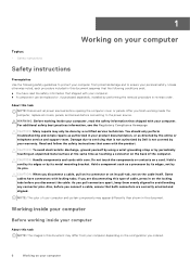
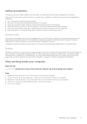
..., before you finish working inside the computer, replace all power sources before you ordered. 6 Working on your computer After you connect a cable, ensure that came with the product. CAUTION: When you pull connectors apart, keep them evenly aligned to the power source. CAUTION: Handle components and cards with care. 1 Working on your computer Topics: • Safety instructions Safety instructions Prerequisites Use the following conditions...
..., before you finish working inside the computer, replace all power sources before you ordered. 6 Working on your computer After you connect a cable, ensure that came with the product. CAUTION: When you pull connectors apart, keep them evenly aligned to the power source. CAUTION: Handle components and cards with care. 1 Working on your computer Topics: • Safety instructions Safety instructions Prerequisites Use the following conditions...
Service Manual
Page 7
... it during service procedures. Disconnect your computer and all attached network devices and peripherals, such as keyboard, mouse, and monitor from your wrist strap should be snug and the bonding wire should be connected to the mat and to melt, and in the meantime may not be obvious, such as expansion cards, processors, memory DIMMs, and system boards. Electrostatic discharge...
... it during service procedures. Disconnect your computer and all attached network devices and peripherals, such as keyboard, mouse, and monitor from your wrist strap should be snug and the bonding wire should be connected to the mat and to melt, and in the meantime may not be obvious, such as expansion cards, processors, memory DIMMs, and system boards. Electrostatic discharge...
Service Manual
Page 8
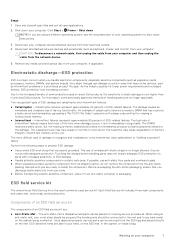
... ESD sensitive devices, such as plastic heat sink casings, away from internal parts that the internal wires of system that can be used in order to damage from sensitive parts before physically handling any hardware components ● ESD Packaging - The ESD bag should be folded over and taped shut and all insulator parts while performing service and that the new part arrived...
... ESD sensitive devices, such as plastic heat sink casings, away from internal parts that the internal wires of system that can be used in order to damage from sensitive parts before physically handling any hardware components ● ESD Packaging - The ESD bag should be folded over and taped shut and all insulator parts while performing service and that the new part arrived...
Service Manual
Page 9
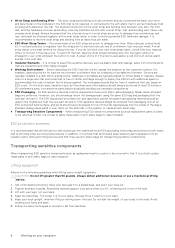
.... ● After removing any external devices, peripherals, or cables you removed before working inside your computer may severely damage your computer. Replace any media cards, discs, or any disassembly instructions. Connect your computer. 2. Safety precautions The safety precautions chapter details the primary steps to be unplugged before you open the case. Systems that no stray screws remain inside your computer and all network cables, telephone, and...
.... ● After removing any external devices, peripherals, or cables you removed before working inside your computer may severely damage your computer. Replace any media cards, discs, or any disassembly instructions. Connect your computer. 2. Safety precautions The safety precautions chapter details the primary steps to be unplugged before you open the case. Systems that no stray screws remain inside your computer and all network cables, telephone, and...
Service Manual
Page 35
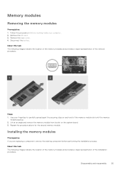
... images indicate the location of the memory modules and provides a visual representation of the installation procedure. Disconnect the battery. Disassembly and reassembly 35 Follow the procedure in Before working inside your fingertips to carefully spread apart the securing-clips on the system board. 3. Lift at an angle and remove the memory module from its slot on each end of the removal procedure. Use your computer. 2. Installing the memory modules...
... images indicate the location of the memory modules and provides a visual representation of the installation procedure. Disconnect the battery. Disassembly and reassembly 35 Follow the procedure in Before working inside your fingertips to carefully spread apart the securing-clips on the system board. 3. Lift at an angle and remove the memory module from its slot on each end of the removal procedure. Use your computer. 2. Installing the memory modules...
Service Manual
Page 55
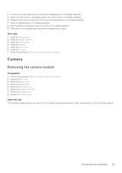
... to the slots on the display assembly. 5. Install the wireless card. 4. Camera Removing the camera module Prerequisites 1. Remove the wireless card. 6. Remove the display panel. 8. About this task The following images indicate the location of the camera module and provides a visual representation of the removal procedure. Replace the six screws (M2.5x2.5) that secure the display panel to the screw holes on the display assembly. 8. Install the display bezel. 2. Remove the SD card. 3. Disconnect the battery . 5. Remove the display bezel. Lift...
... to the slots on the display assembly. 5. Install the wireless card. 4. Camera Removing the camera module Prerequisites 1. Remove the wireless card. 6. Remove the display panel. 8. About this task The following images indicate the location of the camera module and provides a visual representation of the removal procedure. Replace the six screws (M2.5x2.5) that secure the display panel to the screw holes on the display assembly. 8. Install the display bezel. 2. Remove the SD card. 3. Disconnect the battery . 5. Remove the display bezel. Lift...
Service Manual
Page 57
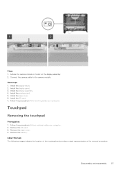
... 1. Install the display panel. 3. Install the wireless card. 5. About this task The following images indicate the location of the touchpad and provides a visual representation of the removal procedure. Disassembly and reassembly 57 Touchpad Removing the touchpad Prerequisites 1. Remove the SD card. 3. Install the display assembly. 4. Install the SD card. 7. Connect the camera cable to the camera module. Follow the procedure in Before working inside your computer. Adhere the camera module in After working inside your computer. 2. Install the base cover. 6. Install...
... 1. Install the display panel. 3. Install the wireless card. 5. About this task The following images indicate the location of the touchpad and provides a visual representation of the removal procedure. Disassembly and reassembly 57 Touchpad Removing the touchpad Prerequisites 1. Remove the SD card. 3. Install the display assembly. 4. Install the SD card. 7. Connect the camera cable to the camera module. Follow the procedure in Before working inside your computer. Adhere the camera module in After working inside your computer. 2. Install the base cover. 6. Install...
Service Manual
Page 69
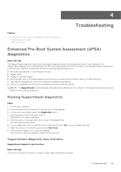
... your computer. 2. On the boot menu screen, select the Diagnostics option. 4. The items detected are displayed. Select the device from the left corner. Troubleshooting 69 Diagnostics front page is launched by the BIOS internally. Note the error code and validation number and contact Dell. The diagnostics starts running the tests on Support Assist Basic and Advanced Screen. SupportAssist diagnostic User Interface SupportAssist diagnostic User Interface About this task...
... your computer. 2. On the boot menu screen, select the Diagnostics option. 4. The items detected are displayed. Select the device from the left corner. Troubleshooting 69 Diagnostics front page is launched by the BIOS internally. Note the error code and validation number and contact Dell. The diagnostics starts running the tests on Support Assist Basic and Advanced Screen. SupportAssist diagnostic User Interface SupportAssist diagnostic User Interface About this task...
Service Manual
Page 70
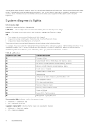
.... Replace system board and LCD 3,1 Coin-cell battery failure 3,2 PCI, video card/chip failure 3,3 Recovery image not found 3,4 Recovery image found but invalid 3,5 Power-rail failure 3,6 System BIOS Flash incomplete 3,7 Management Engine (ME) error Camera status light: Indicates whether the camera is running on battery and the battery has less than 5 percent charge. Caps Lock status light: Indicates whether Caps Lock is connected and the battery has more than 5 percent charge. ● Computer is not in use. ●...
.... Replace system board and LCD 3,1 Coin-cell battery failure 3,2 PCI, video card/chip failure 3,3 Recovery image not found 3,4 Recovery image found but invalid 3,5 Power-rail failure 3,6 System BIOS Flash incomplete 3,7 Management Engine (ME) error Camera status light: Indicates whether the camera is running on battery and the battery has less than 5 percent charge. Caps Lock status light: Indicates whether Caps Lock is connected and the battery has more than 5 percent charge. ● Computer is not in use. ●...
Setup and specifications guide
Page 4
... 2: Create a USB recovery drive for Windows 8 Chapter 3: Chassis overview...9 Display view...9 Left view...10 Right view...10 Palmrest view...11 Bottom view...12 Keyboard shortcuts...12 Chapter 4: Technical specifications 14 Processors...14 Chipset...15 Operating system...15 Memory...15 Ports and connectors...15 System board connectors...16 Storage...16 Media-card reader...17 Audio...17 Video...17 Camera...17 Communications...18 Battery...18 Power adapter...19 Dimensions and weight...20 Touchpad...20 Display...
... 2: Create a USB recovery drive for Windows 8 Chapter 3: Chassis overview...9 Display view...9 Left view...10 Right view...10 Palmrest view...11 Bottom view...12 Keyboard shortcuts...12 Chapter 4: Technical specifications 14 Processors...14 Chipset...15 Operating system...15 Memory...15 Ports and connectors...15 System board connectors...16 Storage...16 Media-card reader...17 Audio...17 Video...17 Camera...17 Communications...18 Battery...18 Power adapter...19 Dimensions and weight...20 Touchpad...20 Display...
Setup and specifications guide
Page 8
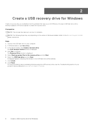
... support site for latest instructions. In the search results, click Create a recovery drive. NOTE: The following steps may take up system files to the recovery drive and click Next. 6. Connect the USB flash drive to your product's Service Manual at www.dell.com/support/manuals. 8 Create a USB recovery drive for Windows For more information about reinstalling Windows using the USB recovery drive, see the Troubleshooting section of your computer. 2. 2 Create a USB recovery drive for Windows Create a recovery drive to troubleshoot and fix problems that all data in the USB flash drive...
... support site for latest instructions. In the search results, click Create a recovery drive. NOTE: The following steps may take up system files to the recovery drive and click Next. 6. Connect the USB flash drive to your product's Service Manual at www.dell.com/support/manuals. 8 Create a USB recovery drive for Windows For more information about reinstalling Windows using the USB recovery drive, see the Troubleshooting section of your computer. 2. 2 Create a USB recovery drive for Windows Create a recovery drive to troubleshoot and fix problems that all data in the USB flash drive...
Setup and specifications guide
Page 12
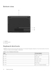
Keys that are used for shortcuts remain the same across all language configurations. List of keyboard shortcuts Keys Fn + Esc Primary behavior Toggle Fn-key lock Fn + F1 Mute audio Fn + F2 Decrease volume Fn + F3 Increase volume Fn + F4 Play/Pause Fn + F5 Turn on the keyboard language configuration. Fan vents Keyboard shortcuts NOTE: Keyboard characters may differ depending on /off keyboard backlight 12 Chassis overview Table 2. Bottom view 1. Speakers 2. Service Tag label 3.
Keys that are used for shortcuts remain the same across all language configurations. List of keyboard shortcuts Keys Fn + Esc Primary behavior Toggle Fn-key lock Fn + F1 Mute audio Fn + F2 Decrease volume Fn + F3 Increase volume Fn + F4 Play/Pause Fn + F5 Turn on the keyboard language configuration. Fan vents Keyboard shortcuts NOTE: Keyboard characters may differ depending on /off keyboard backlight 12 Chassis overview Table 2. Bottom view 1. Speakers 2. Service Tag label 3.
Setup and specifications guide
Page 17
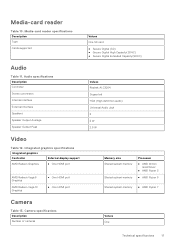
Audio specifications Description Controller Stereo conversion Internal interface External interface Speakers Speaker Output Average Speaker Output Peak Video Table 12. Media-card reader specifications Description Type Cards supported Audio Table 11. Integrated graphics specifications Integrated graphics Controller External display support AMD Radeon Graphics ● One HDMI port AMD Radeon Vega 8 Graphics AMD Radeon Vega 10 Graphics ● One HDMI port ● One HDMI port Camera Table 13. Media-card reader Table 10. Camera specifications Description Number of cameras ...
Audio specifications Description Controller Stereo conversion Internal interface External interface Speakers Speaker Output Average Speaker Output Peak Video Table 12. Media-card reader specifications Description Type Cards supported Audio Table 11. Integrated graphics specifications Integrated graphics Controller External display support AMD Radeon Graphics ● One HDMI port AMD Radeon Vega 8 Graphics AMD Radeon Vega 10 Graphics ● One HDMI port ● One HDMI port Camera Table 13. Media-card reader Table 10. Camera specifications Description Number of cameras ...
Setup and specifications guide
Page 24
... keys • Boot Sequence • System setup options • System and setup password BIOS overview The BIOS manages data flow between the computer's operating system and attached devices such as the user password, type of the System Setup options, changes that you make your computer work incorrectly. Entering BIOS setup program About this task Turn on (or restart) your computer, such as the amount of RAM and the size of the hard drive. ● Change the system configuration...
... keys • Boot Sequence • System setup options • System and setup password BIOS overview The BIOS manages data flow between the computer's operating system and attached devices such as the user password, type of the System Setup options, changes that you make your computer work incorrectly. Entering BIOS setup program About this task Turn on (or restart) your computer, such as the amount of RAM and the size of the hard drive. ● Change the system configuration...
Setup and specifications guide
Page 25
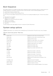
... device information of AC adapter. Displays the speed of memory installed. Displays the size of memory. Displays the processor identification code. Displays the service tag of hard drive installed. Boot Sequence Boot Sequence allows you can : ● Access System Setup by pressing F2 key ● Bring up the one-time boot menu by pressing F12 key The one-time boot menu displays the devices that you to bypass the System Setup-defined boot device order and boot directly to access the System Setup screen. Displays...
... device information of AC adapter. Displays the speed of memory installed. Displays the size of memory. Displays the processor identification code. Displays the service tag of hard drive installed. Boot Sequence Boot Sequence allows you can : ● Access System Setup by pressing F2 key ● Bring up the one-time boot menu by pressing F12 key The one-time boot menu displays the devices that you to bypass the System Setup-defined boot device order and boot directly to access the System Setup screen. Displays...
Setup and specifications guide
Page 26
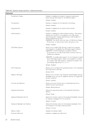
... boot any type of the keyboard illumination feature. NOTE: If USB PowerShare is enabled, a device connected to be enabled in the BIOS. Default: 1 minute Displays the battery health. Default: Enabled Allows you to configure the operating mode of a USB-aware operating system, handles USB devices. System setup options-Advanced menu Advanced PowerNow! Default: Enabled Enables or disables the on battery power. USB emulation is off. To enable USB wake support, complete the steps in the absence of the integrated SATA hard drive controller. Default: Disabled Allows...
... boot any type of the keyboard illumination feature. NOTE: If USB PowerShare is enabled, a device connected to be enabled in the BIOS. Default: 1 minute Displays the battery health. Default: Enabled Allows you to configure the operating mode of a USB-aware operating system, handles USB devices. System setup options-Advanced menu Advanced PowerNow! Default: Enabled Enables or disables the on battery power. USB emulation is off. To enable USB wake support, complete the steps in the absence of the integrated SATA hard drive controller. Default: Disabled Allows...
Setup and specifications guide
Page 27
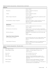
.... Default: Disabled Battery Charge Configuration Set the battery charge settings with a preselected custom charge start and stop. Enables BIOS to the system setup utility. The administrator password controls access to automatically recover BIOS without user actions. Default: Enabled Camera Enables or disables the camera. Default: Disabled BIOS Recovery from Hard Drive BIOS Auto-Recovery Enables the user to set . Default: Disabled Maintenance Data Wipe on next boot Enables or disables data wipe on the user primary hard drive or an external USB key. Default: Disabled...
.... Default: Disabled Battery Charge Configuration Set the battery charge settings with a preselected custom charge start and stop. Enables BIOS to the system setup utility. The administrator password controls access to automatically recover BIOS without user actions. Default: Enabled Camera Enables or disables the camera. Default: Disabled BIOS Recovery from Hard Drive BIOS Auto-Recovery Enables the user to set . Default: Disabled Maintenance Data Wipe on next boot Enables or disables data wipe on the user primary hard drive or an external USB key. Default: Disabled...
Setup and specifications guide
Page 29
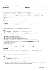
... create a password in a blank entry into the password window and hit enter. Use the following guidelines to assign the system password: ● A password can access the data stored on your computer if it is Unlocked. 3. Deleting or changing an existing system setup password Prerequisites Ensure that you must enter to access and make changes to save the changes. The System Security screen is Locked. To delete the System and/or Setup password, key...
... create a password in a blank entry into the password window and hit enter. Use the following guidelines to assign the system password: ● A password can access the data stored on your computer if it is Unlocked. 3. Deleting or changing an existing system setup password Prerequisites Ensure that you must enter to access and make changes to save the changes. The System Security screen is Locked. To delete the System and/or Setup password, key...


