
Owners Manual
Page 2
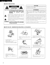
... SHOCK DO NOT OPEN CAUTION: TO REDUCE THE RISK OF ELECTRIC SHOCK, DO NOT REMOVE COVER (OR BACK). NO USER-SERVICEABLE PARTS INSIDE. The exclamation point within the product's enclosure that may be of sufficient magnitude to constitute a risk of electric shock to persons.... This device complies with Part 15 of important operating and maintenance (servicing) instructions in the literature accompanying the appliance. Tenir compte d'une dispersion de chaleur suffisante lors...
... SHOCK DO NOT OPEN CAUTION: TO REDUCE THE RISK OF ELECTRIC SHOCK, DO NOT REMOVE COVER (OR BACK). NO USER-SERVICEABLE PARTS INSIDE. The exclamation point within the product's enclosure that may be of sufficient magnitude to constitute a risk of electric shock to persons.... This device complies with Part 15 of important operating and maintenance (servicing) instructions in the literature accompanying the appliance. Tenir compte d'une dispersion de chaleur suffisante lors...
Owners Manual
Page 3
... to . 4. Outdoor Antenna Grounding - See Figure A. 16. Never push objects of power source indicated on the product. 20. Cleaning - Replacement Parts - Do not use instructions should not be followed. 5. for this product through openings as they exit from heat sources such as this indicates a ...have been adhered to cords at plugs, convenience receptacles, and the point where they may touch dangerous voltage points or short-out parts that are required, be mounted to dangerous voltage or other controls may cause the product and cart combination to insert the plug...
... to . 4. Outdoor Antenna Grounding - See Figure A. 16. Never push objects of power source indicated on the product. 20. Cleaning - Replacement Parts - Do not use instructions should not be followed. 5. for this product through openings as they exit from heat sources such as this indicates a ...have been adhered to cords at plugs, convenience receptacles, and the point where they may touch dangerous voltage points or short-out parts that are required, be mounted to dangerous voltage or other controls may cause the product and cart combination to insert the plug...
Owners Manual
Page 4
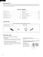
AUX terminal The AVR-1403/483's front panel is provided with an immense array of ...power operation switch to provide superb surround sound listening with a V. ENGLISH 2 INTRODUCTION Thank you want to the following parts are proper and that you review the contents of this manual before proceeding. As this first 8 m Setting up...all other audio components when moving the set. • Before turning the power operation switch on Handling 5 v Features...5 b Part Names and Functions 6, 7 n Read this product is equipped with home theater sources such as DVD, as well as providing...
AUX terminal The AVR-1403/483's front panel is provided with an immense array of ...power operation switch to provide superb surround sound listening with a V. ENGLISH 2 INTRODUCTION Thank you want to the following parts are proper and that you review the contents of this manual before proceeding. As this first 8 m Setting up...all other audio components when moving the set. • Before turning the power operation switch on Handling 5 v Features...5 b Part Names and Functions 6, 7 n Read this product is equipped with home theater sources such as DVD, as well as providing...
Owners Manual
Page 6
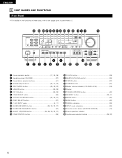
... mode indicators 26) @8 Remote control sensor (REMOTE SENSOR 15) @9 Power operation indicator #0 Input source selector buttons 25, 32) 6 ENGLISH 5 PART NAMES AND FUNCTIONS Front Panel • For details on the functions of these parts, refer to the pages given in parentheses ( ). #0 @9 @8 @7 @6 @5 @4@3 @2 @1 @0 !9 !8 !7 !6 B yi !2 q w e r t u o !0 !1 !3 !4 !5 q Power operation switch 17, 24, 39) w Headphones jack (PHONES 27...
... mode indicators 26) @8 Remote control sensor (REMOTE SENSOR 15) @9 Power operation indicator #0 Input source selector buttons 25, 32) 6 ENGLISH 5 PART NAMES AND FUNCTIONS Front Panel • For details on the functions of these parts, refer to the pages given in parentheses ( ). #0 @9 @8 @7 @6 @5 @4@3 @2 @1 @0 !9 !8 !7 !6 B yi !2 q w e r t u o !0 !1 !3 !4 !5 q Power operation switch 17, 24, 39) w Headphones jack (PHONES 27...

Owners Manual
Page 7
Remote control unit • For details on the functions of these parts, refer to the pages given in parentheses ( ). ENGLISH Remote control signal transmitter 15) INPUT MODE button 25, 28) SURROUND MODE button 26, 29, 30, 32, ...) buttons 21, 23) SYSTEM (SYSTEM SET UP) buttons 16) Cursor buttons 16, 32, 35) Test tone button 29) System buttons (TV 23) CD MD/CDR AVR/AVC ON AUDIO POWER TV VCR VIDEO DVD/VDP OFF 1 CD DVD/VDP 2 3 V. AUX 4 VCR 5 TV/DBS 6 7 INPUT MODE CDR / TAPE TUNER 8 9 0 SURROUND MODE TAPE...
Remote control unit • For details on the functions of these parts, refer to the pages given in parentheses ( ). ENGLISH Remote control signal transmitter 15) INPUT MODE button 25, 28) SURROUND MODE button 26, 29, 30, 32, ...) buttons 21, 23) SYSTEM (SYSTEM SET UP) buttons 16) Cursor buttons 16, 32, 35) Test tone button 29) System buttons (TV 23) CD MD/CDR AVR/AVC ON AUDIO POWER TV VCR VIDEO DVD/VDP OFF 1 CD DVD/VDP 2 3 V. AUX 4 VCR 5 TV/DBS 6 7 INPUT MODE CDR / TAPE TUNER 8 9 0 SURROUND MODE TAPE...
Owners Manual
Page 12
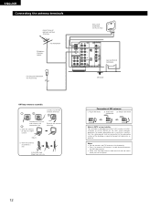
... system installer: This reminder is used, do not disconnect the AM loop antenna. • Make sure AM loop antenna lead terminals do not touch metal parts of AM antennas 1. Return the lever. ENGLISH Connecting the antenna terminals DIRECTION OF BROADCASTING STATION FM ANTENNA 75 Ω/ohms COAXIAL CABLE FM INDOOR ANTENNA...
... system installer: This reminder is used, do not disconnect the AM loop antenna. • Make sure AM loop antenna lead terminals do not touch metal parts of AM antennas 1. Return the lever. ENGLISH Connecting the antenna terminals DIRECTION OF BROADCASTING STATION FM ANTENNA 75 Ω/ohms COAXIAL CABLE FM INDOOR ANTENNA...