
Literature/Product Sheet
Page 2
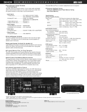
... use . ■ Acclaimed Customization Feature As with remote control codes from other video or pure audio device. • Audio Inputs 7 Analog Inputs CD, TUNER, DVD/VDP, TV/DBS, VCR, CDR/TAPE, V.AUX(FRONT) 6 Analog EXT. DENON ELECTRONICS. These customized features are power amp stage values. NEW MODEL I N F O R M A T I O N AVR-1403 ■ Versatile Input & Output Terminals •...
... use . ■ Acclaimed Customization Feature As with remote control codes from other video or pure audio device. • Audio Inputs 7 Analog Inputs CD, TUNER, DVD/VDP, TV/DBS, VCR, CDR/TAPE, V.AUX(FRONT) 6 Analog EXT. DENON ELECTRONICS. These customized features are power amp stage values. NEW MODEL I N F O R M A T I O N AVR-1403 ■ Versatile Input & Output Terminals •...
Owners Manual
Page 4
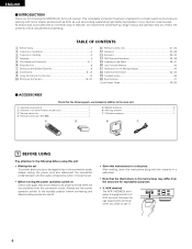
... 93 2 ACCESSORIES Check that the illustrations in addition to the main unit: q Operating instructions 1 w Warranty ( for choosing the DENON A/V Surround receiver. AUX terminal. As this instructions may differ from the actual set for explanation purposes. • V. This remarkable ...; Moving the set To prevent short circuits or damaged wires in a safe place. AUX terminal The AVR-1403/483's front panel is provided with the connection cords. Using the Remote Control Unit 15 ⁄0 Setting up the Speaker Systems 8 , Connections 9~14 . ENGLISH 2 INTRODUCTION Thank...
... 93 2 ACCESSORIES Check that the illustrations in addition to the main unit: q Operating instructions 1 w Warranty ( for choosing the DENON A/V Surround receiver. AUX terminal. As this instructions may differ from the actual set for explanation purposes. • V. This remarkable ...; Moving the set To prevent short circuits or damaged wires in a safe place. AUX terminal The AVR-1403/483's front panel is provided with the connection cords. Using the Remote Control Unit 15 ⁄0 Setting up the Speaker Systems 8 , Connections 9~14 . ENGLISH 2 INTRODUCTION Thank...
Owners Manual
Page 5
...recorded in the memory. 7. 6CH EXT. IN jacks for use with stereo sources not in which the different channels are greatly reduced for DENON remote controllable AV components as well as possible from the tuner or TV. • Set the antenna wires from the tuner or TV away from ... jacks are prestored in Dolby Surround but also regular stereo sources into five channels (front left/right, center and surround left/right). The remote control command codes for several seconds after the muting circuit stops functioning. Dolby Pro Logic II decoder Dolby Pro Logic II is equipped with a...
...recorded in the memory. 7. 6CH EXT. IN jacks for use with stereo sources not in which the different channels are greatly reduced for DENON remote controllable AV components as well as possible from the tuner or TV. • Set the antenna wires from the tuner or TV away from ... jacks are prestored in Dolby Surround but also regular stereo sources into five channels (front left/right, center and surround left/right). The remote control command codes for several seconds after the muting circuit stops functioning. Dolby Pro Logic II decoder Dolby Pro Logic II is equipped with a...
Owners Manual
Page 6
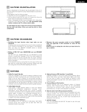
... 26) @1 Display @2 TUNING UP/DOWN button 40) @3 MEMORY button 39, 41) @4 MODE button 40) @5 BAND button 40) @6 SIGNAL indicators 26) @7 INPUT mode indicators 26) @8 Remote control sensor (REMOTE SENSOR 15) @9 Power operation indicator #0 Input source selector buttons 25, 32) 6 ENGLISH 5 PART NAMES AND FUNCTIONS Front Panel • For details on the functions of...
... 26) @1 Display @2 TUNING UP/DOWN button 40) @3 MEMORY button 39, 41) @4 MODE button 40) @5 BAND button 40) @6 SIGNAL indicators 26) @7 INPUT mode indicators 26) @8 Remote control sensor (REMOTE SENSOR 15) @9 Power operation indicator #0 Input source selector buttons 25, 32) 6 ENGLISH 5 PART NAMES AND FUNCTIONS Front Panel • For details on the functions of...

Owners Manual
Page 7
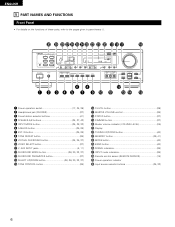
...7 ENGLISH Remote control signal transmitter 15) INPUT MODE button 25, 28) SURROUND MODE button 26, 29, 30, 32, 35) System buttons (TAPE, VCR) buttons 21, 23) SYSTEM (SYSTEM SET UP) buttons 16) Cursor buttons 16, 32, 35) Test tone button 29) System buttons (TV 23) CD MD/CDR AVR/AVC ON ...AUDIO POWER TV VCR VIDEO DVD/VDP OFF 1 CD DVD/VDP 2 3 V. Remote control unit • For details on the functions of these parts, refer to the pages given in parentheses ( ).
...7 ENGLISH Remote control signal transmitter 15) INPUT MODE button 25, 28) SURROUND MODE button 26, 29, 30, 32, 35) System buttons (TAPE, VCR) buttons 21, 23) SYSTEM (SYSTEM SET UP) buttons 16) Cursor buttons 16, 32, 35) Test tone button 29) System buttons (TV 23) CD MD/CDR AVR/AVC ON ...AUDIO POWER TV VCR VIDEO DVD/VDP OFF 1 CD DVD/VDP 2 3 V. Remote control unit • For details on the functions of these parts, refer to the pages given in parentheses ( ).
Owners Manual
Page 8
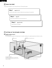
... speaker systems Set these steps. Step 3 (page 16 to setup the Speakers and connecting the components. Step 2 (page 15) Next, insert the batteries into the remote control unit. Step 1 (page 8 to 14) Choose the best location to 20) Finally, setting up the system. 7 SETTING UP THE SPEAKER SYSTEMS 2 Speaker system layout Basic...
... speaker systems Set these steps. Step 3 (page 16 to setup the Speakers and connecting the components. Step 2 (page 15) Next, insert the batteries into the remote control unit. Step 1 (page 8 to 14) Choose the best location to 20) Finally, setting up the system. 7 SETTING UP THE SPEAKER SYSTEMS 2 Speaker system layout Basic...
Owners Manual
Page 9
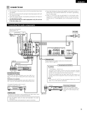
... (LINE IN or REC) to this unit's tape recording (OUT) jacks using pin plug cords. Never connect equipment whose total capacity is supplied from the remote control unit. Connections for playback: Connect the tape deck's playback output jacks (LINE OUT or PB) to this unit's tape playback (IN) jacks using pin plug...
... (LINE IN or REC) to this unit's tape recording (OUT) jacks using pin plug cords. Never connect equipment whose total capacity is supplied from the remote control unit. Connections for playback: Connect the tape deck's playback output jacks (LINE OUT or PB) to this unit's tape playback (IN) jacks using pin plug...
Owners Manual
Page 15
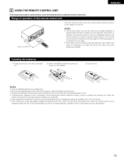
...polarities are obstacles between the remote control unit and the remote control sensor, if the remote control sensor is only for an extended period of time. • If batteries leak, dispose of the remote control unit Point the remote control unit at the remote control sensor as possible.) 15 ...Avoid touching the leaked material or letting it with clothing, etc. ENGLISH 9 USING THE REMOTE CONTROL UNIT Following the procedure outlined below, ...
...polarities are obstacles between the remote control unit and the remote control sensor, if the remote control sensor is only for an extended period of time. • If batteries leak, dispose of the remote control unit Point the remote control unit at the remote control sensor as possible.) 15 ...Avoid touching the leaked material or letting it with clothing, etc. ENGLISH 9 USING THE REMOTE CONTROL UNIT Following the procedure outlined below, ...
Owners Manual
Page 17
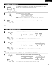
... all the components are correct, then press the POWER operation switch on the main unit or the POWER button on the remote control unit to turn on the power. (Main unit) (Remote control unit) 2 Press the SYSTEM button to enter the setting. *SYSTEM SET UP NOTE: Please make sure the "AUDIO" position ...of the slide switch on the remote control unit. 3 Press the SELECT or (down) button to switch to the speaker configuration set up to that point are entered. NOTE: Press the SYSTEM...
... all the components are correct, then press the POWER operation switch on the main unit or the POWER button on the remote control unit to turn on the power. (Main unit) (Remote control unit) 2 Press the SYSTEM button to enter the setting. *SYSTEM SET UP NOTE: Please make sure the "AUDIO" position ...of the slide switch on the remote control unit. 3 Press the SELECT or (down) button to switch to the speaker configuration set up to that point are entered. NOTE: Press the SYSTEM...
Owners Manual
Page 21
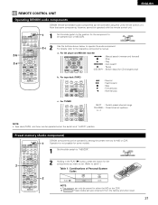
...SURROUND SET UP MENU MASTER CH SELECT VOL SELECT T.TONE STATUS MUTING RETURN DISPLAY CHANNEL TV VOLUME B REMOTE CONTROL UNIT RC-896 1 2 DENON components can be operated by setting the preset memory for either the MD or the CDR. Preset ... Fast-forward 2 : Stop 1 : Forward play 0 : Reverse play c. ENGLISH 0 0 0 0 11 REMOTE CONTROL UNIT Operating DENON audio components DENON remote-controllable audio components can be controlled using this remote control unit. 2-b 2-a CD MD/CDR AVR/AVC ON AUDIO POWER TV VCR VIDEO DVD/VDP OFF 1 CD DVD/VDP 2 3 V. CD AUDIO MD/...
...SURROUND SET UP MENU MASTER CH SELECT VOL SELECT T.TONE STATUS MUTING RETURN DISPLAY CHANNEL TV VOLUME B REMOTE CONTROL UNIT RC-896 1 2 DENON components can be operated by setting the preset memory for either the MD or the CDR. Preset ... Fast-forward 2 : Stop 1 : Forward play 0 : Reverse play c. ENGLISH 0 0 0 0 11 REMOTE CONTROL UNIT Operating DENON audio components DENON remote-controllable audio components can be controlled using this remote control unit. 2-b 2-a CD MD/CDR AVR/AVC ON AUDIO POWER TV VCR VIDEO DVD/VDP OFF 1 CD DVD/VDP 2 3 V. CD AUDIO MD/...
Owners Manual
Page 22
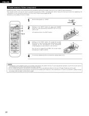
... List of Preset Codes cannot be used to 3. This remote control unit can be operated by registering the manufacturer of the component as shown on pages 92 and 93for the preset codes (consisting of 2-digit numbers). CD MD/CDR AVR/AVC ON AUDIO POWER TV VCR VIDEO DVD/VDP OFF ...1 CD DVD/VDP 2 3 V. w q NOTES: • The signals for some models. See the list on the List of Preset Codes (pages 92, 93). ENGLISH Preset memory (Video component) DENON and other manufacturers without using ...
... List of Preset Codes cannot be used to 3. This remote control unit can be operated by registering the manufacturer of the component as shown on pages 92 and 93for the preset codes (consisting of 2-digit numbers). CD MD/CDR AVR/AVC ON AUDIO POWER TV VCR VIDEO DVD/VDP OFF ...1 CD DVD/VDP 2 3 V. w q NOTES: • The signals for some models. See the list on the List of Preset Codes (pages 92, 93). ENGLISH Preset memory (Video component) DENON and other manufacturers without using ...
Owners Manual
Page 23
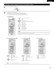
... Switch channel (+, -) NOTE: • The TV can be operated with this remote control unit. d. For monitor TV AVR/AVC ON POWER TV VCR DVD/VDP OFF 1 CD DVD/VDP 2 3 V. b. For video disc player (VDP) AVR/AVC ON POWER TV VCR DVD/VDP OFF 1 CD DVD/VDP 2 3 V....3 9 6 SYSTEM 2 7 SURROUND SET UP MENU MASTER CH SELECT VOL SELECT T.TONE STATUS MUTING RETURN DISPLAY CHANNEL TV VOLUME POWER : Power on remote control for the DVD remote control buttons, so also refer to the instructions on /off 6,7 : Manual search (forward and reverse) 2 : Stop 1 : Play 8,9 : Auto ...
... Switch channel (+, -) NOTE: • The TV can be operated with this remote control unit. d. For monitor TV AVR/AVC ON POWER TV VCR DVD/VDP OFF 1 CD DVD/VDP 2 3 V. b. For video disc player (VDP) AVR/AVC ON POWER TV VCR DVD/VDP OFF 1 CD DVD/VDP 2 3 V....3 9 6 SYSTEM 2 7 SURROUND SET UP MENU MASTER CH SELECT VOL SELECT T.TONE STATUS MUTING RETURN DISPLAY CHANNEL TV VOLUME POWER : Power on remote control for the DVD remote control buttons, so also refer to the instructions on /off 6,7 : Manual search (forward and reverse) 2 : Stop 1 : Play 8,9 : Auto ...

Owners Manual
Page 24
... turns off, the standby mode is pressed, the power turns on and off . ENGLISH 12 OPERATION Before operating B 1 2 CD MD/CDR AUDIO VIDEO POWER 1 AVR/AVC TV ON VCR DVD/VDP OFF 1 CD DVD/VDP 2 3 V. Press the SPEAKER A or B button to the built-in muting circuit that all connections... 2 Select the front speakers. Press the ON/STANDBY button on the main unit or AVR/AVC button on the remote control unit to turn the speaker on the power. This is due to turn on the power. (Main unit) (Remote control unit) • ON/STANDBY When the button is set to the "ON" position...
... turns off, the standby mode is pressed, the power turns on and off . ENGLISH 12 OPERATION Before operating B 1 2 CD MD/CDR AUDIO VIDEO POWER 1 AVR/AVC TV ON VCR DVD/VDP OFF 1 CD DVD/VDP 2 3 V. Press the SPEAKER A or B button to the built-in muting circuit that all connections... 2 Select the front speakers. Press the ON/STANDBY button on the main unit or AVR/AVC button on the remote control unit to turn the speaker on the power. This is due to turn on the power. (Main unit) (Remote control unit) • ON/STANDBY When the button is set to the "ON" position...
Owners Manual
Page 25
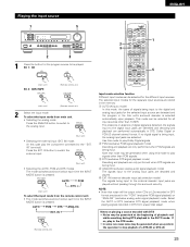
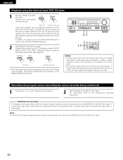
IN" terminal.) Press the EXT. IN 8 (Remote control unit) 2 3 CD MD/CDR AVR/AVC ON AUDIO POWER TV VCR VIDEO DVD/VDP OFF 1 CD DVD/VDP 2 3 V. AUX 4 VCR 5 TV/DBS 6 7 INPUT MODE CDR / TAPE TUNER 8 9 0 SURROUND MODE ... stereo) format. The selected input modes for the separate input sources are decoded and played. EX 1: CD CD 1 (Main unit) EX 2: CDR/TAPE (Remote control unit) CDR / TAPE 8 (Main unit) (Remote control unit) 2 Select the input mode. ENGLISH Playing the input source 1 5 B 2 3 1 Press the button for the program source to be generated when...
IN" terminal.) Press the EXT. IN 8 (Remote control unit) 2 3 CD MD/CDR AVR/AVC ON AUDIO POWER TV VCR VIDEO DVD/VDP OFF 1 CD DVD/VDP 2 3 V. AUX 4 VCR 5 TV/DBS 6 7 INPUT MODE CDR / TAPE TUNER 8 9 0 SURROUND MODE ... stereo) format. The selected input modes for the separate input sources are decoded and played. EX 1: CD CD 1 (Main unit) EX 2: CDR/TAPE (Remote control unit) CDR / TAPE 8 (Main unit) (Remote control unit) 2 Select the input mode. ENGLISH Playing the input source 1 5 B 2 3 1 Press the button for the program source to be generated when...
Owners Manual
Page 26
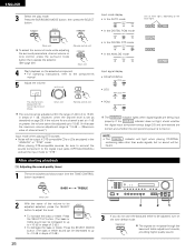
MASTER VOLUME MASTER VOL The volume level is displayed on the master volume level display. (Main unit) (Remote control unit) The volume can be adjusted up to 18 dB. (In this case the maximum volume adjustment range is set the input mode to .... 26 SURROUND MODE (Main unit) To select the surround mode while adjusting the surround parameters, channel volume or tone control, press the surround mode button then operate the selector. (See page 29.) (Remote control unit) (Main unit) 4 Start playback on . NOTE: • The DIGITAL indicator will light when playing CD-ROMs containing ...
MASTER VOLUME MASTER VOL The volume level is displayed on the master volume level display. (Main unit) (Remote control unit) The volume can be adjusted up to 18 dB. (In this case the maximum volume adjustment range is set the input mode to .... 26 SURROUND MODE (Main unit) To select the surround mode while adjusting the surround parameters, channel volume or tone control, press the surround mode button then operate the selector. (See page 29.) (Remote control unit) (Main unit) 4 Start playback on . NOTE: • The DIGITAL indicator will light when playing CD-ROMs containing ...
Owners Manual
Page 27
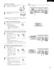
[2] Listening over headphones 1 Connect the headphones to the PHONES jack of the unit's operations are turned on (Main unit) (Remote control unit) 1 VIDEO SELECT CD·MD/CDR·DVD/VDP DISC SKIP+ TITLE 8 3 9 the display. 2 6 7 Cancelling simulcast playback. •... desired source appears on . [3] Turning the sound off temporarily (muting) 1 Use this to check the unit's operating status (Main unit) (Remote control unit) while playing a source by pressing the main unit's DIMMER button repeatedly. (Main unit) The brightness changes in four steps (bright, medium...
[2] Listening over headphones 1 Connect the headphones to the PHONES jack of the unit's operations are turned on (Main unit) (Remote control unit) 1 VIDEO SELECT CD·MD/CDR·DVD/VDP DISC SKIP+ TITLE 8 3 9 the display. 2 6 7 Cancelling simulcast playback. •... desired source appears on . [3] Turning the sound off temporarily (muting) 1 Use this to check the unit's operating status (Main unit) (Remote control unit) while playing a source by pressing the main unit's DIMMER button repeatedly. (Main unit) The brightness changes in four steps (bright, medium...
Owners Manual
Page 28
...), the play modes other than the external input mode, the signals connected to these jacks cannot be set to switch the external input. (Main unit) (Remote control unit) Once this mode. B 21 1, 2 V. AUX 4 VCR 5 TV/DBS 6 7 INPUT MODE CDR / TAPE TUNER 8 9 0 SURROUND MODE TAPE·VCR 6 7 SHIFT ... the INPUT MODE (AUTO, PCM, DTS) or ANALOG button to switch to the desired input mode. (See page 25.) 8 (Main unit) (Remote control unit) • When the input mode is selected, the input signals connected to the CDR/TAPE and VCR AUDIO OUT jacks. 28 Recording the program...
...), the play modes other than the external input mode, the signals connected to these jacks cannot be set to switch the external input. (Main unit) (Remote control unit) Once this mode. B 21 1, 2 V. AUX 4 VCR 5 TV/DBS 6 7 INPUT MODE CDR / TAPE TUNER 8 9 0 SURROUND MODE TAPE·VCR 6 7 SHIFT ... the INPUT MODE (AUTO, PCM, DTS) or ANALOG button to switch to the desired input mode. (See page 25.) 8 (Main unit) (Remote control unit) • When the input mode is selected, the input signals connected to the CDR/TAPE and VCR AUDIO OUT jacks. 28 Recording the program...
Owners Manual
Page 29
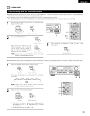
...Pro Logic II or Dolby Digital or DTS) modes. The adjusted playback levels for all the speakers. (Remote control unit) NOTE: Please make sure the "AUDIO" position of the slide switch on the remote control unit. 1 SURROUND MODE TAPE·VCR 6 7 0 3 2 CHANNEL 0 VIDEO SELECT CD·...make sure the "AUDIO" position of the slide switch on the remote control unit. 2 Adjust the level of the selected speaker. (Main unit) (Remote control unit) The level of the selected speaker can be performed from the remote control unit, as shown below . 1 Select the speaker whose level ...
...Pro Logic II or Dolby Digital or DTS) modes. The adjusted playback levels for all the speakers. (Remote control unit) NOTE: Please make sure the "AUDIO" position of the slide switch on the remote control unit. 1 SURROUND MODE TAPE·VCR 6 7 0 3 2 CHANNEL 0 VIDEO SELECT CD·...make sure the "AUDIO" position of the slide switch on the remote control unit. 2 Adjust the level of the selected speaker. (Main unit) (Remote control unit) The level of the selected speaker can be performed from the remote control unit, as shown below . 1 Select the speaker whose level ...

Owners Manual
Page 30
... 3 9 6 SYSTEM 2 7 SURROUND SET UP MENU MASTER CH SELECT VOL SELECT T.TONE STATUS MUTING RETURN DISPLAY CHANNEL TV VOLUME B REMOTE CONTROL UNIT RC-896 6 Set the surround parameters according to the manuals of the respective components. 4 Select the surround parameter mode. SURROUND MODE (...time the button is set to "AUDIO". 5 Select the optimum mode for the source. (Main unit) (Remote control unit) MODE PRO LOGIC MODE CINEMA MODE MUSIC or or 1 2 4, 6 2, 5, 7 1 2 4, 5, 6, 7 CD MD/CDR AVR/AVC ON AUDIO POWER TV VCR VIDEO DVD/VDP OFF 1 CD DVD/VDP 2 3 V.
... 3 9 6 SYSTEM 2 7 SURROUND SET UP MENU MASTER CH SELECT VOL SELECT T.TONE STATUS MUTING RETURN DISPLAY CHANNEL TV VOLUME B REMOTE CONTROL UNIT RC-896 6 Set the surround parameters according to the manuals of the respective components. 4 Select the surround parameter mode. SURROUND MODE (...time the button is set to "AUDIO". 5 Select the optimum mode for the source. (Main unit) (Remote control unit) MODE PRO LOGIC MODE CINEMA MODE MUSIC or or 1 2 4, 6 2, 5, 7 1 2 4, 5, 6, 7 CD MD/CDR AVR/AVC ON AUDIO POWER TV VCR VIDEO DVD/VDP OFF 1 CD DVD/VDP 2 3 V.
Owners Manual
Page 32
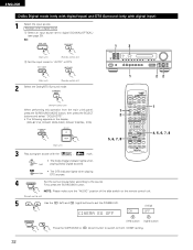
...MODE button, then press the SELECT buttons and select "DOLBY/DTS". • The following appears on the remote control unit. (Remote control unit) 5 Use the (left ) button (right) button (down) button to switch to digital (...COAXIAL/OPTICAL) (see page 20). ENGLISH Dolby Digital mode (only with digital input) and DTS Surround (only with the , mark. DIGITAL • The Dolby Digital indicator lights when Light playing Dolby Digital sources. 1 22 1 2 5, 6, 7, 8 CD MD/CDR AVR...
...MODE button, then press the SELECT buttons and select "DOLBY/DTS". • The following appears on the remote control unit. (Remote control unit) 5 Use the (left ) button (right) button (down) button to switch to digital (...COAXIAL/OPTICAL) (see page 20). ENGLISH Dolby Digital mode (only with digital input) and DTS Surround (only with the , mark. DIGITAL • The Dolby Digital indicator lights when Light playing Dolby Digital sources. 1 22 1 2 5, 6, 7, 8 CD MD/CDR AVR...


