
Instruction Manual
Page 3
English TABLE OF CONTENTS IMPORTANT SAFETY INSTRUCTIONS FOR ALL TOOLS 2 GROUNDING INSTRUCTIONS 2 ADDITIONAL SAFETY RULES FOR WET TILE SAWS 3 QUICK START GUIDE 4 FEATURES ...6 ASSEMBLY ...6 SPECIFICATIONS ...7 OPERATION ...7 TOOL PLACEMENT 7 MOTOR ...7 ON/OFF SWITCH 7 WATER NOZZLES 7 CUTTING WHEEL ALIGNMENT 7 CUTTING WHEEL DEPTH 7 MAKING A CUT 7 LOCKING THE CUTTING CART 8 TYPES OF CUT 8 ADJUSTMENTS 9 MAINTENANCE...10 BRUSHES 10 TRANSPORTATION AND STORAGE 10 CLEANING 10 LUBRICATION 10 REPAIRS ...10 ACCESSORIES ...10 WARRANTY ...10 TROUBLESHOOTING GUIDE 11 1
English TABLE OF CONTENTS IMPORTANT SAFETY INSTRUCTIONS FOR ALL TOOLS 2 GROUNDING INSTRUCTIONS 2 ADDITIONAL SAFETY RULES FOR WET TILE SAWS 3 QUICK START GUIDE 4 FEATURES ...6 ASSEMBLY ...6 SPECIFICATIONS ...7 OPERATION ...7 TOOL PLACEMENT 7 MOTOR ...7 ON/OFF SWITCH 7 WATER NOZZLES 7 CUTTING WHEEL ALIGNMENT 7 CUTTING WHEEL DEPTH 7 MAKING A CUT 7 LOCKING THE CUTTING CART 8 TYPES OF CUT 8 ADJUSTMENTS 9 MAINTENANCE...10 BRUSHES 10 TRANSPORTATION AND STORAGE 10 CLEANING 10 LUBRICATION 10 REPAIRS ...10 ACCESSORIES ...10 WARRANTY ...10 TROUBLESHOOTING GUIDE 11 1

Instruction Manual
Page 4
... moving parts. when changing accessories, such as cutting wheels, clamps, extensions, and the like , extending from electric shock. Make sure switch is equipped with a 3-conductor cord and 3-prong grounding type plug to protect the operator from the adapter must be plugged into a matching outlet that shown in a risk of power and overheating. The use depending on . • KEEP WORK AREA CLEAN. English Important Safety Instructions for All Tools...
... moving parts. when changing accessories, such as cutting wheels, clamps, extensions, and the like , extending from electric shock. Make sure switch is equipped with a 3-conductor cord and 3-prong grounding type plug to protect the operator from the adapter must be plugged into a matching outlet that shown in a risk of power and overheating. The use depending on . • KEEP WORK AREA CLEAN. English Important Safety Instructions for All Tools...

Instruction Manual
Page 5
... OPERATE SAW WITHOUT COVERS IN PLACE. TURN POWER OFF. Be sure all knobs and clamp handles are on the skin may contribute to harmful airborne dust. • Turn off the ground. Force cutting action. Place hands closer than 3" (76 mm) from saw cutting wheel. • DO - ON COLUMN WARNING: FOR YOUR OWN SAFETY, READ INSTRUCTION MANUAL BEFORE OPERATING TILE SAW. TURN OFF TOOL AND WAIT FOR CUTTING WHEEL TO STOP BEFORE MOVING WORK PIECE OR CHANGING SETTINGS. NEVER CUT A PIECE...
... OPERATE SAW WITHOUT COVERS IN PLACE. TURN POWER OFF. Be sure all knobs and clamp handles are on the skin may contribute to harmful airborne dust. • Turn off the ground. Force cutting action. Place hands closer than 3" (76 mm) from saw cutting wheel. • DO - ON COLUMN WARNING: FOR YOUR OWN SAFETY, READ INSTRUCTION MANUAL BEFORE OPERATING TILE SAW. TURN OFF TOOL AND WAIT FOR CUTTING WHEEL TO STOP BEFORE MOVING WORK PIECE OR CHANGING SETTINGS. NEVER CUT A PIECE...

Instruction Manual
Page 6
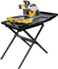
... wrench supplied, install and tighten the two screws closest to To Attach Cutting Wheel in Figure 1. When servicing this tool, use only identical replacement parts. Pull the rubber side flap back and lift the cover toward the rear of the cutting wheel cover. REPLACE DAMAGED CUTTING WHEEL BEFORE OPERATING. YOU CAN PREVENT ACCIDENTS. Install the motor arm onto frame assembly. FIG. 1 4 Step 2 2. a. Remove outer flange. THINK! Quick Start Guide D24000 Wet Tile Saw Step 1 1. Press spindle lock button. Install...
... wrench supplied, install and tighten the two screws closest to To Attach Cutting Wheel in Figure 1. When servicing this tool, use only identical replacement parts. Pull the rubber side flap back and lift the cover toward the rear of the cutting wheel cover. REPLACE DAMAGED CUTTING WHEEL BEFORE OPERATING. YOU CAN PREVENT ACCIDENTS. Install the motor arm onto frame assembly. FIG. 1 4 Step 2 2. a. Remove outer flange. THINK! Quick Start Guide D24000 Wet Tile Saw Step 1 1. Press spindle lock button. Install...

Instruction Manual
Page 7
...saw in pan, as shown. 7. The pump should always be in full open position. NOTE: Make sure the cart lock is properly adjusted to the water line and insert pump power cord into the socket. For further details, refer to Assembly in the Instruction Manual. Align the arrow on the frame of the cutting wheel should be sure that the cutting wheel depth... pump in the Instruction Manual. Attach the cutting cart to clear the cart stop. Tilt the front of cut knob (BB) and tighten the locking wing nut (MM), then the head lock knob BB (D). Adjust the depth of the cart upward...
...saw in pan, as shown. 7. The pump should always be in full open position. NOTE: Make sure the cart lock is properly adjusted to the water line and insert pump power cord into the socket. For further details, refer to Assembly in the Instruction Manual. Align the arrow on the frame of the cutting wheel should be sure that the cutting wheel depth... pump in the Instruction Manual. Attach the cutting cart to clear the cart stop. Tilt the front of cut knob (BB) and tighten the locking wing nut (MM), then the head lock knob BB (D). Adjust the depth of the cart upward...

Instruction Manual
Page 8
... angle. Cutting wheel M. Water nozzles G. Place saw . 2. Install the other two holes and tighten. 5. Place the threaded fitting onto the water pump (N). Place the water pump in Figure 2. 6. Using the smaller Allen wrench supplied, loosen (do not remove) the screw (R) on the side of the cutting cart assembly (H) down on a stable surface. 2. Press spindle lock button. A On/Off switch I ). Motor arm assembly attachment C. Head lock knob K. Rear water attachment N. Using the supplied wrench remove...
... angle. Cutting wheel M. Water nozzles G. Place saw . 2. Install the other two holes and tighten. 5. Place the threaded fitting onto the water pump (N). Place the water pump in Figure 2. 6. Using the smaller Allen wrench supplied, loosen (do not remove) the screw (R) on the side of the cutting cart assembly (H) down on a stable surface. 2. Press spindle lock button. A On/Off switch I ). Motor arm assembly attachment C. Head lock knob K. Rear water attachment N. Using the supplied wrench remove...

Instruction Manual
Page 9
... the switch is that part of this manual. Before turning the saw locks on a level surface. Always keep hands away from dipping onto the receptacle or plug. These extension cords are intended for outdoor use with the edge guide lock (W). If the cutting wheel height is not centered in contact with the minimum amount of nozzles to tighten. All DEWALT tools are adjustable to provide maximum water for insertion...
... the switch is that part of this manual. Before turning the saw locks on a level surface. Always keep hands away from dipping onto the receptacle or plug. These extension cords are intended for outdoor use with the edge guide lock (W). If the cutting wheel height is not centered in contact with the minimum amount of nozzles to tighten. All DEWALT tools are adjustable to provide maximum water for insertion...

Instruction Manual
Page 10
... the cutting wheel. After the cutting wheel stops, remove the tile from traveling too deep and cutting into the cutting wheel. Locking the Cutting Cart (Fig. 13) There are utilized when removing the center of a piece of tile for electrical outlets and for making any adjustments or removing or installing attachments or accessories. See Adjustments for the cart. Pull the on/off switch up to turn the saw on and wait for air...
... the cutting wheel. After the cutting wheel stops, remove the tile from traveling too deep and cutting into the cutting wheel. Locking the Cutting Cart (Fig. 13) There are utilized when removing the center of a piece of tile for electrical outlets and for making any adjustments or removing or installing attachments or accessories. See Adjustments for the cart. Pull the on/off switch up to turn the saw on and wait for air...

Instruction Manual
Page 11
...;, 22.5˚ or 45˚. Turn off , push the cart past the cutting wheel before making any adjustments or removing or installing attachments or accessories. Cut into the bucket. Adjust the two rail height adjusters (JJ) until the cutting wheel is necessary. 1. Rotate cut knob and tighten the locking wing nut (MM), then the head lock knob (D). NOTE: The corners may result. Loosen the four rail assembly mounting screws (HH). 4. Mark the tile...
...;, 22.5˚ or 45˚. Turn off , push the cart past the cutting wheel before making any adjustments or removing or installing attachments or accessories. Cut into the bucket. Adjust the two rail height adjusters (JJ) until the cutting wheel is necessary. 1. Rotate cut knob and tighten the locking wing nut (MM), then the head lock knob (D). NOTE: The corners may result. Loosen the four rail assembly mounting screws (HH). 4. Mark the tile...

Instruction Manual
Page 12
... not required on the guide rail or wheels. 6. In addition to the warranty, DEWALT tools are covered by our: 1 YEAR FREE SERVICE DEWALT will repair, without charge, any adjustments or removing or installing attachments or accessories. Spray the cutting cart with a hose or wipe with a grout sponge or a rag. Spray lubricants are missing, call 1-800-4-DEWALT (1-800-4339258). Inspect carbon brushes regularly by normal use, for free, any time during...
... not required on the guide rail or wheels. 6. In addition to the warranty, DEWALT tools are covered by our: 1 YEAR FREE SERVICE DEWALT will repair, without charge, any adjustments or removing or installing attachments or accessories. Spray the cutting cart with a hose or wipe with a grout sponge or a rag. Spray lubricants are missing, call 1-800-4-DEWALT (1-800-4339258). Inspect carbon brushes regularly by normal use, for free, any time during...

Instruction Manual
Page 13
English Troubleshooting Guide BE SURE TO FOLLOW SAFETY RULES AND INSTRUCTIONS MANY COMMON PROBLEMS CAN BE SOLVED EASILY BY UTILIZING THE CHART BELOW. TROUBLE! Saw will not pump water 3. Cord damaged 6. Brushes worn out WHAT TO DO... 1. Turn cutting wheel around. Change the cutting wheel. Arbor loose 2. Tighten arbor 3. Saw not mounted securely to fence 3. Cutting wheel is not perpendicular to fence 2. Use edge guide. 11 GFCI tripped 3. Fuse blown or circuit breaker tripped 5. Push switch to off and...
English Troubleshooting Guide BE SURE TO FOLLOW SAFETY RULES AND INSTRUCTIONS MANY COMMON PROBLEMS CAN BE SOLVED EASILY BY UTILIZING THE CHART BELOW. TROUBLE! Saw will not pump water 3. Cord damaged 6. Brushes worn out WHAT TO DO... 1. Turn cutting wheel around. Change the cutting wheel. Arbor loose 2. Tighten arbor 3. Saw not mounted securely to fence 3. Cutting wheel is not perpendicular to fence 2. Use edge guide. 11 GFCI tripped 3. Fuse blown or circuit breaker tripped 5. Push switch to off and...

Parts Diagram
Page 2
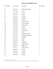
Please visit www.dewaltservicenet.com for D24000S Type 1 Description Qty Required NAMEPLATE 1 FIELD CASE 1 FIELD 1 ARMATURE & BRGS 1 BALL BEARING 1 BALL BEARING 1 RETAINING RING 1 SCREW 5 BEARING CUP 1 BUSHING,STR.RLF 1 ARBOR NUT 1 CLAMP WASHER 1 CLAMP WASHER 1 SCREW 1 GEAR CASE COVER ASSY. 1 BALL BEARING 1 SCREW 16 ARM 1 LABEL 1 BEARING,NEEDLE 1 SPINDLE LOCK 1 FELT WIPER 1 SPRING 2 SPINDLE LOCK BUTTON 1 LINER 1 SCREW 4 HANDLE 1 COPYRIGHT© 2005. Page 1 All Rights Reserved. Item Number 1 2 3 4 5 6 7 10 12 13 16 17 18...
Please visit www.dewaltservicenet.com for D24000S Type 1 Description Qty Required NAMEPLATE 1 FIELD CASE 1 FIELD 1 ARMATURE & BRGS 1 BALL BEARING 1 BALL BEARING 1 RETAINING RING 1 SCREW 5 BEARING CUP 1 BUSHING,STR.RLF 1 ARBOR NUT 1 CLAMP WASHER 1 CLAMP WASHER 1 SCREW 1 GEAR CASE COVER ASSY. 1 BALL BEARING 1 SCREW 16 ARM 1 LABEL 1 BEARING,NEEDLE 1 SPINDLE LOCK 1 FELT WIPER 1 SPRING 2 SPINDLE LOCK BUTTON 1 LINER 1 SCREW 4 HANDLE 1 COPYRIGHT© 2005. Page 1 All Rights Reserved. Item Number 1 2 3 4 5 6 7 10 12 13 16 17 18...

Parts Diagram
Page 3
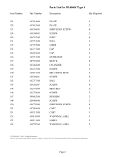
Please visit www.dewaltservicenet.com for D24000S Type 1 Description Qty Required SCREW 17 GUARD ASSEMBLY 1 COVER 1 INSERT 4 SLEEVE 1 RETAINER 1 NOSE 1 MANIFOLD 1 NOZZLE 2 O-RING 4 PLATE 1 LEVER 1 SCREW 1 RETAINER 1 SHOULDER SCREW 11 FLAPPER 1 SCREW 18 WASHER 12 FLAPPER 1 WASHER 1 GUARD ASSEMBLY 1 COVER 1 LABEL 1 CAUTION LABEL 1 SCREW 1 SPACER 1 SHOULDER SCREW 1 COPYRIGHT© 2005. All Rights Reserved. Page 2 Parts list, pricing, and availability subject to change. Item Number 36 37 37 38 39 40 41 42...
Please visit www.dewaltservicenet.com for D24000S Type 1 Description Qty Required SCREW 17 GUARD ASSEMBLY 1 COVER 1 INSERT 4 SLEEVE 1 RETAINER 1 NOSE 1 MANIFOLD 1 NOZZLE 2 O-RING 4 PLATE 1 LEVER 1 SCREW 1 RETAINER 1 SHOULDER SCREW 11 FLAPPER 1 SCREW 18 WASHER 12 FLAPPER 1 WASHER 1 GUARD ASSEMBLY 1 COVER 1 LABEL 1 CAUTION LABEL 1 SCREW 1 SPACER 1 SHOULDER SCREW 1 COPYRIGHT© 2005. All Rights Reserved. Page 2 Parts list, pricing, and availability subject to change. Item Number 36 37 37 38 39 40 41 42...

Parts Diagram
Page 4
...-01 618123-00 627525-00 Parts List for current parts information. Page 3 Please visit www.dewaltservicenet.com for D24000S Type 1 Description Qty Required SCREW 1 TRUNNION 1 PIVOT SHAFT 1 PIVOT SHAFT 1 SPACER 2 SPRING 1 BUSHING 4 SET SCREW 4 BEVEL KNOB 1 KNOB 1 SET SCREW 1 BRACKET 1 KNOB 1 WASHER 2 BOLT 1 BUSHING 1 PIN 1 RETAINING RING 1 SET SCREW 1 COLUMN 1 WARNING LABEL 1 PLATE 1 WRENCH 1 HEX WRENCH 1 CLIP 1 CLIP 1 SUPPORT ARM 1 COPYRIGHT© 2005. All Rights Reserved. Parts list, pricing, and availability subject to change.
...-01 618123-00 627525-00 Parts List for current parts information. Page 3 Please visit www.dewaltservicenet.com for D24000S Type 1 Description Qty Required SCREW 1 TRUNNION 1 PIVOT SHAFT 1 PIVOT SHAFT 1 SPACER 2 SPRING 1 BUSHING 4 SET SCREW 4 BEVEL KNOB 1 KNOB 1 SET SCREW 1 BRACKET 1 KNOB 1 WASHER 2 BOLT 1 BUSHING 1 PIN 1 RETAINING RING 1 SET SCREW 1 COLUMN 1 WARNING LABEL 1 PLATE 1 WRENCH 1 HEX WRENCH 1 CLIP 1 CLIP 1 SUPPORT ARM 1 COPYRIGHT© 2005. All Rights Reserved. Parts list, pricing, and availability subject to change.
Parts Diagram
Page 5
...-00 619683-00 612775-00 612673-00 Parts List for current parts information. Parts list, pricing, and availability subject to change. Please visit www.dewaltservicenet.com for D24000S Type 1 Description Qty Required SHOULDER SCREW 3 PLATE 1 PLATE 1 LABEL 1 COVER 1 END CAP 1 SWITCH 1 SWITCH PLATE 1 SWITCH BEZEL 1 ENCLOSURE 1 SCREW 28 COVER 1 ENCLOSURE 1 CORD 1 TERMINAL,MALE 4 TERMINAL,FEMALE 6 BUSHING 5 CORD 1 CORD 1 TERMINAL 2 CORD & PLUG 1 WIRE CLIP 1 SCREW,M4-U0 3 SCREW 2 CLAMP 4 ELBOW 1 FRAME 1 COPYRIGHT© 2005. Page...
...-00 619683-00 612775-00 612673-00 Parts List for current parts information. Parts list, pricing, and availability subject to change. Please visit www.dewaltservicenet.com for D24000S Type 1 Description Qty Required SHOULDER SCREW 3 PLATE 1 PLATE 1 LABEL 1 COVER 1 END CAP 1 SWITCH 1 SWITCH PLATE 1 SWITCH BEZEL 1 ENCLOSURE 1 SCREW 28 COVER 1 ENCLOSURE 1 CORD 1 TERMINAL,MALE 4 TERMINAL,FEMALE 6 BUSHING 5 CORD 1 CORD 1 TERMINAL 2 CORD & PLUG 1 WIRE CLIP 1 SCREW,M4-U0 3 SCREW 2 CLAMP 4 ELBOW 1 FRAME 1 COPYRIGHT© 2005. Page...
Parts Diagram
Page 6
Page 5 Parts list, pricing, and availability subject to change. Please visit www.dewaltservicenet.com for D24000S Type 1 Description Qty Required PLATE 1 PLATE 2 SHOULDER SCREW 4 SCREW 2 FOOT 4 RAIL 1 LINER 1 CAP 1 CAP 1 GUIDE ROD 1 BLOCK 4 CYLINDER 1 SCREW 1 RETAINING RING 1 SCREW 8 RAIL 1 SCREW 4 BRACKET 2 SCREW 2 BUSHING 2 SCREW 1 SHOULDER SCREW 4 CART 1 CART 1 WARNING LABEL 1 LABEL 1 WARNING LABEL 2 COPYRIGHT© 2005. Item Number 121 122 123 124 129 131 132 133 134 136...
Page 5 Parts list, pricing, and availability subject to change. Please visit www.dewaltservicenet.com for D24000S Type 1 Description Qty Required PLATE 1 PLATE 2 SHOULDER SCREW 4 SCREW 2 FOOT 4 RAIL 1 LINER 1 CAP 1 CAP 1 GUIDE ROD 1 BLOCK 4 CYLINDER 1 SCREW 1 RETAINING RING 1 SCREW 8 RAIL 1 SCREW 4 BRACKET 2 SCREW 2 BUSHING 2 SCREW 1 SHOULDER SCREW 4 CART 1 CART 1 WARNING LABEL 1 LABEL 1 WARNING LABEL 2 COPYRIGHT© 2005. Item Number 121 122 123 124 129 131 132 133 134 136...
Parts Diagram
Page 7
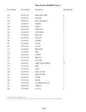
Page 6 Parts list, pricing, and availability subject to change. Please visit www.dewaltservicenet.com for D24000S Type 1 Description Qty Required ROLLER GUIDE 3 SPACER 6 BALL BEARING 9 SCREW 3 SHAFT 3 STOP NUT 6 CYLINDER 1 ROLLER 3 SPACER 3 SCREW 3 PLATE 1 SCALE 1 BRACKET 1 ROD 1 SCREW 1 BRUSH 1 GUTTER 2 SHOULDER SCREW 12 DISC 1 STOP 1 COLLECTOR 1 EDGE GUIDE 1 GUIDE 1 KNOB 2 CLAMPING PLATE 1 TUBING 1 VALVE 1 COPYRIGHT© 2005. Item Number 155 157 158 159 160 161 162 164 165 166 167 169 171 172 173...
Page 6 Parts list, pricing, and availability subject to change. Please visit www.dewaltservicenet.com for D24000S Type 1 Description Qty Required ROLLER GUIDE 3 SPACER 6 BALL BEARING 9 SCREW 3 SHAFT 3 STOP NUT 6 CYLINDER 1 ROLLER 3 SPACER 3 SCREW 3 PLATE 1 SCALE 1 BRACKET 1 ROD 1 SCREW 1 BRUSH 1 GUTTER 2 SHOULDER SCREW 12 DISC 1 STOP 1 COLLECTOR 1 EDGE GUIDE 1 GUIDE 1 KNOB 2 CLAMPING PLATE 1 TUBING 1 VALVE 1 COPYRIGHT© 2005. Item Number 155 157 158 159 160 161 162 164 165 166 167 169 171 172 173...

Parts Diagram
Page 8
...213 214 215 216 217 218 Part Number 612780-00 616779-00 622978-00...Parts List for current parts information. All Rights Reserved. Please visit www.dewaltservicenet.com for D24000S Type 1 Description Qty Required PUMP 1 FITTING 1 PAN 1 EXTENSION 1 STOPPER 1 TRAY 1 BEVEL POINTER 1 SCREW 1 SCREW 4 SCREW 2 WING NUT 1 SET SCREW 1 COVER 1 SCREW 2 LEAD 1 LEAD ASSY. 1 TERMINAL BLOCK 1 ROPE 1 COVER 3 SCREW 2 EXTENSION 1 SCALE 1 GUIDE PIN 2 NUT 2 INSERT 1 DISC 1 SCREW 4 COPYRIGHT© 2005. Parts list, pricing, and availability subject to change...
...213 214 215 216 217 218 Part Number 612780-00 616779-00 622978-00...Parts List for current parts information. All Rights Reserved. Please visit www.dewaltservicenet.com for D24000S Type 1 Description Qty Required PUMP 1 FITTING 1 PAN 1 EXTENSION 1 STOPPER 1 TRAY 1 BEVEL POINTER 1 SCREW 1 SCREW 4 SCREW 2 WING NUT 1 SET SCREW 1 COVER 1 SCREW 2 LEAD 1 LEAD ASSY. 1 TERMINAL BLOCK 1 ROPE 1 COVER 3 SCREW 2 EXTENSION 1 SCALE 1 GUIDE PIN 2 NUT 2 INSERT 1 DISC 1 SCREW 4 COPYRIGHT© 2005. Parts list, pricing, and availability subject to change...

Parts Diagram
Page 9
... 612688-00 635225-00 496555-00 5140058-96 5140058-97 5140058-98 790206-00 DW4762 DW4764 Parts List for current parts information. All Rights Reserved. Please visit www.dewaltservicenet.com for D24000S Type 1 Description Qty Required WASHER 2 PIN 1 LATCH 1 RETAINING CLIP 1 SCREW 1 O-RING 1 WASHER 3 SPRING 1 SLEEVE 1 CORD CLIP 1 INSERT 4 BRUSH 2 BRUSH HOLDER 2 BRUSH CAP 2 SET SCREW 2 SCREW 2 ROLLER 3 SHIELD 1 EDGE GUIDE 1 GFCI PLUG 1 SCREEN 1 GASKET 1 COVER 1 SCREW 3 GREASE, 6 OZ. 1 CUTTING WHEEL 1 BLADE 1 COPYRIGHT© 2005.
... 612688-00 635225-00 496555-00 5140058-96 5140058-97 5140058-98 790206-00 DW4762 DW4764 Parts List for current parts information. All Rights Reserved. Please visit www.dewaltservicenet.com for D24000S Type 1 Description Qty Required WASHER 2 PIN 1 LATCH 1 RETAINING CLIP 1 SCREW 1 O-RING 1 WASHER 3 SPRING 1 SLEEVE 1 CORD CLIP 1 INSERT 4 BRUSH 2 BRUSH HOLDER 2 BRUSH CAP 2 SET SCREW 2 SCREW 2 ROLLER 3 SHIELD 1 EDGE GUIDE 1 GFCI PLUG 1 SCREEN 1 GASKET 1 COVER 1 SCREW 3 GREASE, 6 OZ. 1 CUTTING WHEEL 1 BLADE 1 COPYRIGHT© 2005.

Parts Diagram
Page 10
Please visit www.dewaltservicenet.com for D24000S Type 1 Description Qty Required CUTTING WHEEL 1 CUTTING WHEEL 1 COPYRIGHT© 2005. Parts list, pricing, and availability subject to change. Page 9 Item Number 856 856 Part Number DW4760 DW4761 Parts List for current parts information. All Rights Reserved.
Please visit www.dewaltservicenet.com for D24000S Type 1 Description Qty Required CUTTING WHEEL 1 CUTTING WHEEL 1 COPYRIGHT© 2005. Parts list, pricing, and availability subject to change. Page 9 Item Number 856 856 Part Number DW4760 DW4761 Parts List for current parts information. All Rights Reserved.


