
Instruction Manual
Page 3
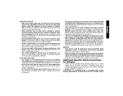
.... • Maintain tools with care. Follow instructions in tools that the grinding wheel backing flange has a yellow rubber ring (S) installed, see Figure 1. See page 9 for Grinders • Check that have the tool serviced before plugging in unexpected situations. • Use safety equipment. Holding the work by the manufacturer for your body...
.... • Maintain tools with care. Follow instructions in tools that the grinding wheel backing flange has a yellow rubber ring (S) installed, see Figure 1. See page 9 for Grinders • Check that have the tool serviced before plugging in unexpected situations. • Use safety equipment. Holding the work by the manufacturer for your body...
Instruction Manual
Page 5
... the wheel is in motion or kickback may contribute to hearing loss. Lock On Button (D28402) C. Slider Switch (D28110, F. 4-1/2" Grinding Wheel D28112) G. Never attempt to remove the unit from the work . Some examples of work or pull the unit backward while the wheel is not engaged... into a corner because a sudden, sharp movement of the grinder may promote absorption of harmful chemicals. Always use . Direct particles away from this tool can be controlled by the operator, if proper precautions ...
... the wheel is in motion or kickback may contribute to hearing loss. Lock On Button (D28402) C. Slider Switch (D28110, F. 4-1/2" Grinding Wheel D28112) G. Never attempt to remove the unit from the work . Some examples of work or pull the unit backward while the wheel is not engaged... into a corner because a sudden, sharp movement of the grinder may promote absorption of harmful chemicals. Always use . Direct particles away from this tool can be controlled by the operator, if proper precautions ...

Instruction Manual
Page 6
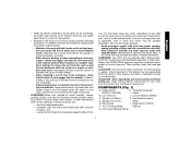
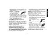
..../lbs. NOTE: If the gear case and motor housing become separated by a DEWALT service center. Before reconnecting the tool, depress and release the trigger switch to firmly... 1. Separating the gear case from tool. 2. Overtightening could cause screws to use with grinder accessories. Failure to 18 in the threaded holes, as shown. Tighten screws to have the...3. Before using the tool, check that the tool is tightened securely. English FIG. 1 C D28402 D28402N F D28110 D28112 S IA B J K (D28402) L L K G H K ASSEMBLY AND ADJUSTMENTS ATTACHING SIDE HANDLE The side ...
..../lbs. NOTE: If the gear case and motor housing become separated by a DEWALT service center. Before reconnecting the tool, depress and release the trigger switch to firmly... 1. Separating the gear case from tool. 2. Overtightening could cause screws to use with grinder accessories. Failure to 18 in the threaded holes, as shown. Tighten screws to have the...3. Before using the tool, check that the tool is tightened securely. English FIG. 1 C D28402 D28402N F D28110 D28112 S IA B J K (D28402) L L K G H K ASSEMBLY AND ADJUSTMENTS ATTACHING SIDE HANDLE The side ...

Instruction Manual
Page 8
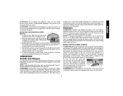
... body should not be posi- tioned between the spindle and the operator to secure the guard on the gear O case hub. Do not operate the grinder with the slots (O) on the guard with a loose guard or the clamp lever in the closed . I ) into the desired working po sition. You should be...
... body should not be posi- tioned between the spindle and the operator to secure the guard on the gear O case hub. Do not operate the grinder with the slots (O) on the guard with a loose guard or the clamp lever in the closed . I ) into the desired working po sition. You should be...
Instruction Manual
Page 9
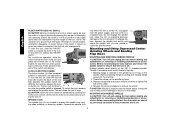
...such as the activation of a ground fault interrupter, throwing of the tool firmly to secure the guard on tool nameplate. Do not operate grinder with the clamp lever in open position. NOTE: Edge grinding and cutting can be performed with Type 27 wheels designed and specified for at... guards and flanges to run while the switch is depressed. Wheels and other accessories running over rated accessory speed may result. Allow the grinder to use and until the guard lug engages and rotates freely in power supply to provide maximum operator protection. 4. ing the lock-on...
...such as the activation of a ground fault interrupter, throwing of the tool firmly to secure the guard on tool nameplate. Do not operate grinder with the clamp lever in open position. NOTE: Edge grinding and cutting can be performed with Type 27 wheels designed and specified for at... guards and flanges to run while the switch is depressed. Wheels and other accessories running over rated accessory speed may result. Allow the grinder to use and until the guard lug engages and rotates freely in power supply to provide maximum operator protection. 4. ing the lock-on...
Instruction Manual
Page 10
...is turned off and unplug the tool before making any adjustments or removing or installing attachments or accessories. Backing flange is retained to the grinder by hand. 3. To start unexpectedly. For continuous operation, slide the switch toward the front of the tool then depress the paddle ...off position by pulling and twisting flange away form the machine. 2. Depress the spindle lock button and use applications. English SLIDER SWITCH (D28110, D28112) CAUTION: Before connecting the tool to a power supply, be sure the switch is in the off . If the switch is locked on...
...is turned off and unplug the tool before making any adjustments or removing or installing attachments or accessories. Backing flange is retained to the grinder by hand. 3. To start unexpectedly. For continuous operation, slide the switch toward the front of the tool then depress the paddle ...off position by pulling and twisting flange away form the machine. 2. Depress the spindle lock button and use applications. English SLIDER SWITCH (D28110, D28112) CAUTION: Before connecting the tool to a power supply, be sure the switch is in the off . If the switch is locked on...
Instruction Manual
Page 13
... extra care when working over an edge, as previously described to avoid creating gouges in a circular motion causes burning and swirling marks on the grinder spindle without moving, or moving the tool in a circular motion causes burning and swirling marks on and off as a sudden sharp movement of ... tool in a forward and back motion to ensure that the tool is required when using wire brushes and wheels. English 2. mately one inch of grinder may result in use a wrench on may be used for removing rust, scale and paint, and for wire cup brushes. 4. Allowing the tool...
... extra care when working over an edge, as previously described to avoid creating gouges in a circular motion causes burning and swirling marks on the grinder spindle without moving, or moving the tool in a circular motion causes burning and swirling marks on and off as a sudden sharp movement of ... tool in a forward and back motion to ensure that the tool is required when using wire brushes and wheels. English 2. mately one inch of grinder may result in use a wrench on may be used for removing rust, scale and paint, and for wire cup brushes. 4. Allowing the tool...

Instruction Manual
Page 14
.... MOUNTING CLOSED (TYPE 1) GUARD CAUTION: Turn off and unplug the tool before making any adjustments or removing or installing attachments or acces- Do not operate grinder with clamp lever in open position. CAUTION: Do not tighten adjusting screw with a loose guard or clamp lever in open position. 5. Before reconnecting the tool...
.... MOUNTING CLOSED (TYPE 1) GUARD CAUTION: Turn off and unplug the tool before making any adjustments or removing or installing attachments or acces- Do not operate grinder with clamp lever in open position. CAUTION: Do not tighten adjusting screw with a loose guard or clamp lever in open position. 5. Before reconnecting the tool...


