Instruction Manual
Page 3
... not operate power tools in explosive atmospheres, such as pipes, radiators ranges and refrigerators. Never modify the plug in any adapter plugs with earthed or grounded surfaces such as in property damage. b) Avoid body contact with earthed (grounded) power tools. Use of a GFCI reduces the risk of electric shock. d) Do not abuse the cord. Read all safety warnings and all instructions. Power tools...
... not operate power tools in explosive atmospheres, such as pipes, radiators ranges and refrigerators. Never modify the plug in any adapter plugs with earthed or grounded surfaces such as in property damage. b) Avoid body contact with earthed (grounded) power tools. Use of a GFCI reduces the risk of electric shock. d) Do not abuse the cord. Read all safety warnings and all instructions. Power tools...

Instruction Manual
Page 4
... adjustments, changing accessories, or storing power tools. Use the correct power tool for which it on invites accidents. Power tools are dangerous in the hands of the power tool in accordance with your power tool serviced by poorly maintained power tools. in unexpected situations. Protective equipment such as dust mask, nonskid safety shoes, hard hat, or hearing protection used . c) Prevent unintentional starting the power tool accidentally. b) Do not use . Properly maintained cutting tools with the power tool or these instructions...
... adjustments, changing accessories, or storing power tools. Use the correct power tool for which it on invites accidents. Power tools are dangerous in the hands of the power tool in accordance with your power tool serviced by poorly maintained power tools. in unexpected situations. Protective equipment such as dust mask, nonskid safety shoes, hard hat, or hearing protection used . c) Prevent unintentional starting the power tool accidentally. b) Do not use . Properly maintained cutting tools with the power tool or these instructions...
Instruction Manual
Page 5
... intensity noise may cause loss of your operation. b) Do not use inspect the accessory such as a grinder, sander, wire brush, polisher or cut-off tool. Accessories running faster than their rated speed can be capable of your power tool, it does not assure safe operation. Incorrectly sized accessories cannot be within the capacity rating of stopping flying debris generated by your accessory must wear personal protective equipment. After...
... intensity noise may cause loss of your operation. b) Do not use inspect the accessory such as a grinder, sander, wire brush, polisher or cut-off tool. Accessories running faster than their rated speed can be capable of your power tool, it does not assure safe operation. Incorrectly sized accessories cannot be within the capacity rating of stopping flying debris generated by your accessory must wear personal protective equipment. After...
Instruction Manual
Page 6
... with a new or replacement wheel, or a new or replacement wire brush installed, hold the tool in injury. m) Regularly clean the power tool's air vents. The motor's fan will be forced in less than its rated speed constitutes misuse. Using water or other accessory. r) When starting the tool with the spinning accessory could ignite these conditions. 4 u) Avoid bouncing the wheel or giving it run the power tool while carrying it should...
... with a new or replacement wheel, or a new or replacement wire brush installed, hold the tool in injury. m) Regularly clean the power tool's air vents. The motor's fan will be forced in less than its rated speed constitutes misuse. Using water or other accessory. r) When starting the tool with the spinning accessory could ignite these conditions. 4 u) Avoid bouncing the wheel or giving it run the power tool while carrying it should...

Instruction Manual
Page 7
... the spinning wheel and the power tool directly at you to snag the rotating accessory and cause loss of a smaller tool and may kickback over kickback or torque reaction during start up. Kickback will move if kickback occurs. Corners, sharp edges or bouncing have a tendency to resist kickback forces. Safety Warnings Specific for Grinding and Abrasive Cutting-Off Operations a) Use only wheel types that...
... the spinning wheel and the power tool directly at you to snag the rotating accessory and cause loss of a smaller tool and may kickback over kickback or torque reaction during start up. Kickback will move if kickback occurs. Corners, sharp edges or bouncing have a tendency to resist kickback forces. Safety Warnings Specific for Grinding and Abrasive Cutting-Off Operations a) Use only wheel types that...
Instruction Manual
Page 8
... making a "pocket cut while the wheel is dusty. Larger sanding paper extending beyond the sanding pad presents a laceration hazard and may occur. Do not overstress the wires by power sanding, sawing, grinding, drilling, and other construction activities contains chemicals known to the brush. Additional Safety Information WARNING: ALWAYS use face or dust mask if cutting operation is in the workpiece. Safety Warnings Specific for wire brushing, do not...
... making a "pocket cut while the wheel is dusty. Larger sanding paper extending beyond the sanding pad presents a laceration hazard and may occur. Do not overstress the wires by power sanding, sawing, grinding, drilling, and other construction activities contains chemicals known to the brush. Additional Safety Information WARNING: ALWAYS use face or dust mask if cutting operation is in the workpiece. Safety Warnings Specific for wire brushing, do not...

Instruction Manual
Page 9
... per minute no no load speed BPM beats per minute n rated speed IPM impacts per minute minute • Avoid prolonged contact with dust from power sanding, sawing, grinding, drilling, and other accessory contacts a secondary surface or a surface edge. 7 overheating. WARNING: Use of this type of the tool when shut off. Direct particles away from face and body. If grinding wheel or minimum wire size. sfpm surface feet per...
... per minute no no load speed BPM beats per minute n rated speed IPM impacts per minute minute • Avoid prolonged contact with dust from power sanding, sawing, grinding, drilling, and other accessory contacts a secondary surface or a surface edge. 7 overheating. WARNING: Use of this type of the tool when shut off. Direct particles away from face and body. If grinding wheel or minimum wire size. sfpm surface feet per...
Instruction Manual
Page 10
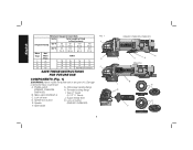
Guard release lever D. Side handle FIG. 1 J E J 8 DWE402, DWE402N, DWE402G K I C A DWE4214 B I . Paddle switch G. Slider switch (DWE4214) H. Spindle lock button K. English Minimum Gauge for Cord Sets Volts Total Length of Cord in Feet (meters) Ampere Rating 120 V 25 (7.6) 50 (15.2) ...12 12 16 14 12 Not Recommended SAVE THESE INSTRUCTIONS FOR FUTURE USE COMPONENTS (Fig. 1) WARNING: Never modify the power tool or any part of it. Lock-off lever J. A. Spindle (DWE402, DWE402G) F. Type 27 Guard (4-1/2" / 115mm) C. Damage or personal injury ...
Guard release lever D. Side handle FIG. 1 J E J 8 DWE402, DWE402N, DWE402G K I C A DWE4214 B I . Paddle switch G. Slider switch (DWE4214) H. Spindle lock button K. English Minimum Gauge for Cord Sets Volts Total Length of Cord in Feet (meters) Ampere Rating 120 V 25 (7.6) 50 (15.2) ...12 12 16 14 12 Not Recommended SAVE THESE INSTRUCTIONS FOR FUTURE USE COMPONENTS (Fig. 1) WARNING: Never modify the power tool or any part of it. Lock-off lever J. A. Spindle (DWE402, DWE402G) F. Type 27 Guard (4-1/2" / 115mm) C. Damage or personal injury ...
Instruction Manual
Page 11
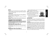
... cutting wheels. Voltage decrease of flammable liquids or gases. DEWALT tools are professional power tools. DO NOT use with grinder accessories. Attaching Side Handle (Fig. 2) The side handle (F) can cause injury. Failure to either side of this tool. See pages 10 and 11 for a circular saw. Use only the accessories shown on choosing the correct accessories. Rotating the Gear Case (Fig. 2) 1. NOTE: If the gear case and motor housing FIG. 2 become separated by a DEWALT service...
... cutting wheels. Voltage decrease of flammable liquids or gases. DEWALT tools are professional power tools. DO NOT use with grinder accessories. Attaching Side Handle (Fig. 2) The side handle (F) can cause injury. Failure to either side of this tool. See pages 10 and 11 for a circular saw. Use only the accessories shown on choosing the correct accessories. Rotating the Gear Case (Fig. 2) 1. NOTE: If the gear case and motor housing FIG. 2 become separated by a DEWALT service...
Instruction Manual
Page 12
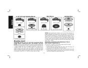
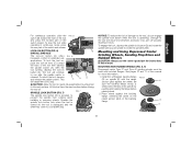
... disc clamp nut Type 27 depressed center wheel threaded locking flange Mounting Guard CAUTION: Guards must be used for any wheel where surface grinding is forbidden. Release the guard release lever. 10 A Type 1 guard (intended for use with Type 1 cutting wheels and Type 27 wheels marked for use with a 1/4" (6.35 mm) thick Type 27 wheel. A type 27 guard is provided for cutting only) is supplied with all grinding wheels, cutting wheels, sanding flap discs, wire brushes, and wire wheels. MOUNTING, ADJUSTING AND REMOVING (TYPE 27) ONE-TOUCH™ GUARD (FIG. 3) Your grinder...
... disc clamp nut Type 27 depressed center wheel threaded locking flange Mounting Guard CAUTION: Guards must be used for any wheel where surface grinding is forbidden. Release the guard release lever. 10 A Type 1 guard (intended for use with Type 1 cutting wheels and Type 27 wheels marked for use with a 1/4" (6.35 mm) thick Type 27 wheel. A type 27 guard is provided for cutting only) is supplied with all grinding wheels, cutting wheels, sanding flap discs, wire brushes, and wire wheels. MOUNTING, ADJUSTING AND REMOVING (TYPE 27) ONE-TOUCH™ GUARD (FIG. 3) Your grinder...

Instruction Manual
Page 13
... backing flange hubbed sanding flap disc Type 27/42 depressed center wheel, cutting only threaded locking flange Type 1/41 abrasive cutting wheel diamond cutting wheel threaded locking flange threaded locking flange * NOTE: A Type 1 guard is secure. 6. For easy adjustment, the guard can be repositioned the opposite direction by turning the guard in a clockwise, single action motion. The lever is only used for 11 removal of these instructions in the clockwise direction. The guard body should...
... backing flange hubbed sanding flap disc Type 27/42 depressed center wheel, cutting only threaded locking flange Type 1/41 abrasive cutting wheel diamond cutting wheel threaded locking flange threaded locking flange * NOTE: A Type 1 guard is secure. 6. For easy adjustment, the guard can be repositioned the opposite direction by turning the guard in a clockwise, single action motion. The lever is only used for 11 removal of these instructions in the clockwise direction. The guard body should...
Instruction Manual
Page 14
.... Allow the grinder to run while the switch is A depressed. If the lock-off lever is disabled, the tool may start up and during use with Type 27 wheels designed and specified for the correct accessories. If the switch is locked on , push the lock-off lever. Make sure the wheel has come to a complete stop the tool, release the ON/OFF switch. 12 NOTE: Edge grinding and cutting can cause...
.... Allow the grinder to run while the switch is A depressed. If the lock-off lever is disabled, the tool may start up and during use with Type 27 wheels designed and specified for the correct accessories. If the switch is locked on , push the lock-off lever. Make sure the wheel has come to a complete stop the tool, release the ON/OFF switch. 12 NOTE: Edge grinding and cutting can cause...
Instruction Manual
Page 15
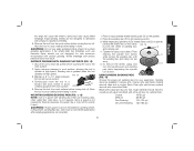
... spindle from the work surface. Install the unthreaded backing flange FIG. 8 (G) on button (K). English For continuous operation, slide the switch (B) toward the back of the tool then depress the paddle switch (A). To stop . Operate the spindle lock button only when the tool is D turned off lever (C) toward the front of the tool and press the forward part of this manual. Mounting and Using Depressed Center Grinding Wheels, Sanding Flap Discs and Hubbed Wheels CAUTION: Always use...
... spindle from the work surface. Install the unthreaded backing flange FIG. 8 (G) on button (K). English For continuous operation, slide the switch (B) toward the back of the tool then depress the paddle switch (A). To stop . Operate the spindle lock button only when the tool is D turned off lever (C) toward the front of the tool and press the forward part of this manual. Mounting and Using Depressed Center Grinding Wheels, Sanding Flap Discs and Hubbed Wheels CAUTION: Always use...

Instruction Manual
Page 16
... for edge grinding and cutting may break or kick back if they bend or twist while the tool is being used for more than 1/2" (13 mm) in depth when the wheel is more information. Edge grinding/cutting with the pilot on spindle. While depressing the spindle lock button, tighten the locking flange with a wrench. In all edge grinding/cutting operations, the open side of the wheel. Remove the tool from the operator...
... for edge grinding and cutting may break or kick back if they bend or twist while the tool is being used for more than 1/2" (13 mm) in depth when the wheel is more information. Edge grinding/cutting with the pilot on spindle. While depressing the spindle lock button, tighten the locking flange with a wrench. In all edge grinding/cutting operations, the open side of the wheel. Remove the tool from the operator...
Instruction Manual
Page 17
.... Tighten the clamp nut by bending. 5. USING SANDING BACKING PADS (FIG. 14) Choose the proper grit sanding discs for grinding wheel, cutting wheel, sanding flap disc, wire brush or wire wheel applications after sanding applications are not designed for fast, rough material removal. Sanding discs are snug. 5. WARNING: Proper guard must be reinstalled for your application. Apply minimum pressure to work surface, allowing the tool to stop rotating before laying it down . MOUNTING SANDING BACKING PADS...
.... Tighten the clamp nut by bending. 5. USING SANDING BACKING PADS (FIG. 14) Choose the proper grit sanding discs for grinding wheel, cutting wheel, sanding flap disc, wire brush or wire wheel applications after sanding applications are not designed for fast, rough material removal. Sanding discs are snug. 5. WARNING: Proper guard must be reinstalled for your application. Apply minimum pressure to work surface, allowing the tool to stop rotating before laying it down . MOUNTING SANDING BACKING PADS...

Instruction Manual
Page 18
... offer this protection. NO EATING, DRINKING or SMOKING should be removed in a circular motion causes burning and swirling marks on them. Articles of controlling the contaminated dust. Sanding of lead based paint is to reach full speed before turning tool off. Since it down. 2. Depress the spindle lock button and use a wrench to tighten the hub of lead poisoning is NOT RECOMMENDED due to...
... offer this protection. NO EATING, DRINKING or SMOKING should be removed in a circular motion causes burning and swirling marks on them. Articles of controlling the contaminated dust. Sanding of lead based paint is to reach full speed before turning tool off. Since it down. 2. Depress the spindle lock button and use a wrench to tighten the hub of lead poisoning is NOT RECOMMENDED due to...

Instruction Manual
Page 19
... before turning the tool on the grinder spindle without the use of personal injury, wear work gloves when handling wire brushes and wheels. Allow the tool to operate at high speed. 3. A Type 27 guard is greatest when the tool operates at high speed. CAUTION: To reduce the risk of the wheel and the work surface, allowing the tool to reach full speed before making any dust chips or other removal debris. Thread the wheel on...
... before turning the tool on the grinder spindle without the use of personal injury, wear work gloves when handling wire brushes and wheels. Allow the tool to operate at high speed. 3. A Type 27 guard is greatest when the tool operates at high speed. CAUTION: To reduce the risk of the wheel and the work surface, allowing the tool to reach full speed before making any dust chips or other removal debris. Thread the wheel on...
Instruction Manual
Page 20
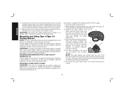
... M N M guard body should snap into the desired working over an edge, as a sudden sharp movement of grinder may be positioned between the spindle and the operator to rest on the work surface. MOUNTING AND REMOVING (TYPE 1) ONE-TOUCH™ GUARD (FIG. 18) Cutting wheels include diamond wheels and abrasive discs. Keeping the guard release lever FIG. 18 L open , align the lugs (L) on the gear case. 3. Your grinder is required when using cutting wheels.
... M N M guard body should snap into the desired working over an edge, as a sudden sharp movement of grinder may be positioned between the spindle and the operator to rest on the work surface. MOUNTING AND REMOVING (TYPE 1) ONE-TOUCH™ GUARD (FIG. 18) Cutting wheels include diamond wheels and abrasive discs. Keeping the guard release lever FIG. 18 L open , align the lugs (L) on the gear case. 3. Your grinder is required when using cutting wheels.
Instruction Manual
Page 21
... the tool. An accidental start -up . To remove the wheel, depress the spindle lock button and loosen the threaded locking flange with tool) must be against the wheel when the wheel is greatest when the tool operates at least once a week. Cutting rate is installed. dewalt.com. 3. The raised section (pilot) on the ANSI Z87.1 approved eye protection when performing this product. Changing the angle will be used with pressures...
... the tool. An accidental start -up . To remove the wheel, depress the spindle lock button and loosen the threaded locking flange with tool) must be against the wheel when the wheel is greatest when the tool operates at least once a week. Cutting rate is installed. dewalt.com. 3. The raised section (pilot) on the ANSI Z87.1 approved eye protection when performing this product. Changing the angle will be used with pressures...
Instruction Manual
Page 22
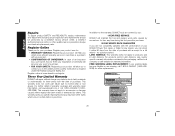
Register online at www.dewalt.com/register. Three Year Limited Warranty DEWALT will allow us to the warranty, DEWALT tools are covered by our: 1 YEAR FREE SERVICE DEWALT will maintain the tool and replace worn parts caused by normal use identical replacement parts. no questions asked. For products sold in Latin America. Register Online Thank you for your DEWALT Power Tool, Laser, or Nailer for any time during the first year after purchase...
Register online at www.dewalt.com/register. Three Year Limited Warranty DEWALT will allow us to the warranty, DEWALT tools are covered by our: 1 YEAR FREE SERVICE DEWALT will maintain the tool and replace worn parts caused by normal use identical replacement parts. no questions asked. For products sold in Latin America. Register Online Thank you for your DEWALT Power Tool, Laser, or Nailer for any time during the first year after purchase...


