Hardware Reference
Page 4
Chapter 3 Appendix A Brocade 5100 configuration 10 Providing power to the switch 10 Creating a serial connection 11 Switch IP address 11 Date and time settings 12 Brocade 5100 Operation In this chapter 17 Powering the Brocade 5100 ...5100 24 Brocade 5100 Specifications In this appendix 27 Switch components 27 Weight and physical dimensions 28 Facility requirements 28 Power supply specifications 28 Environmental requirements 29 General specifications 29 Data transmission ranges 30 Memory specifications 31 Fibre Channel port specifications 31 Serial port specifications 32 iv ...
Chapter 3 Appendix A Brocade 5100 configuration 10 Providing power to the switch 10 Creating a serial connection 11 Switch IP address 11 Date and time settings 12 Brocade 5100 Operation In this chapter 17 Powering the Brocade 5100 ...5100 24 Brocade 5100 Specifications In this appendix 27 Switch components 27 Weight and physical dimensions 28 Facility requirements 28 Power supply specifications 28 Environmental requirements 29 General specifications 29 Data transmission ranges 30 Memory specifications 31 Fibre Channel port specifications 31 Serial port specifications 32 iv ...

Hardware Reference
Page 7
...1, "Brocade 5100 Introduction," provides an overview of the Brocade 5100 switch, a feature list, and a look at the appearance of the switch. • Chapter 2, "Brocade 5100 Installation and Configuration," provides the information needed to install the switch into your network. • Chapter 3, "Brocade 5100 Operation," ...discusses the day-to-day operational procedures for using the switch. • Appendix A, "Brocade 5100 Specifications," provides tables of physical, environmental, and general specifications, helpful for Fabric...
...1, "Brocade 5100 Introduction," provides an overview of the Brocade 5100 switch, a feature list, and a look at the appearance of the switch. • Chapter 2, "Brocade 5100 Installation and Configuration," provides the information needed to install the switch into your network. • Chapter 3, "Brocade 5100 Operation," ...discusses the day-to-day operational procedures for using the switch. • Appendix A, "Brocade 5100 Specifications," provides tables of physical, environmental, and general specifications, helpful for Fabric...

Hardware Reference
Page 10
... cost for hardware, firmware, and software support, including product repairs and part ordering. To expedite your switch support supplier for a user ID and password. It's free! For practical discussions about the Fibre Channel industry, visit the Fibre Channel Industry Association Web site: http://www.fibrechannel.org Getting technical help Contact your call, have the following...
... cost for hardware, firmware, and software support, including product repairs and part ordering. To expedite your switch support supplier for a user ID and password. It's free! For practical discussions about the Fibre Channel industry, visit the Fibre Channel Industry Association Web site: http://www.fibrechannel.org Getting technical help Contact your call, have the following...
Hardware Reference
Page 11
... you can get the WWN from the same place as the serial number, except for improvement. If you cannot use the wwn command because the switch is inoperable, you . For the Brocade DCX, access the numbers on the port side of the document and as much detail as illustrated below.: *FT00X0054E9... located as follows: • Brocade 200E-On the non-port side of the chassis • Brocade 300, 4100, 4900, 5100, 5300, 7500, and Brocade Encryption Switch-On the switch ID pull-out tab located inside the chassis on the port side on the left • Brocade 5000-On the...
... you can get the WWN from the same place as the serial number, except for improvement. If you cannot use the wwn command because the switch is inoperable, you . For the Brocade DCX, access the numbers on the port side of the document and as much detail as illustrated below.: *FT00X0054E9... located as follows: • Brocade 200E-On the non-port side of the chassis • Brocade 300, 4100, 4900, 5100, 5300, 7500, and Brocade Encryption Switch-On the switch ID pull-out tab located inside the chassis on the port side on the left • Brocade 5000-On the...

Hardware Reference
Page 13
...Demand license 5 •ISL trunking groups 5 Brocade 5100 overview The Brocade 5100 is an Enterprise class 1U, 40-port Fibre Channel 1, 2, 4 or 8 Gbps Fibre Channel switch that offers the next generation Brocade, single-chip architecture for configuration uploads and downloads • Single motherboard design with 667...is the latest mid-range offer from 24 to 32 or 40 ports. • Support for 1, 2, 4, and 8 Gbps auto-sensing Fibre Channel switch and router ports. • FICON®, FICON Cascading and FICON Control Unit Port ready. • Two hot-swappable, redundant integrated power...
...Demand license 5 •ISL trunking groups 5 Brocade 5100 overview The Brocade 5100 is an Enterprise class 1U, 40-port Fibre Channel 1, 2, 4 or 8 Gbps Fibre Channel switch that offers the next generation Brocade, single-chip architecture for configuration uploads and downloads • Single motherboard design with 667...is the latest mid-range offer from 24 to 32 or 40 ports. • Support for 1, 2, 4, and 8 Gbps auto-sensing Fibre Channel switch and router ports. • FICON®, FICON Cascading and FICON Control Unit Port ready. • Two hot-swappable, redundant integrated power...

Hardware Reference
Page 14
... transceivers support any combination of Short Wavelength (SWL), Long Wavelength (LWL) or Extended Long Wavelength (ELWL) optical media among the switch ports. • Brocade Fabric Operating System (Fabric OS), which enables native Fibre Channel extension greater than 590 km. • Expanded security for optimal bandwidth utilization and load balancing. • Dynamic Path Selection...
... transceivers support any combination of Short Wavelength (SWL), Long Wavelength (LWL) or Extended Long Wavelength (ELWL) optical media among the switch ports. • Brocade Fabric Operating System (Fabric OS), which enables native Fibre Channel extension greater than 590 km. • Expanded security for optimal bandwidth utilization and load balancing. • Dynamic Path Selection...
Hardware Reference
Page 15
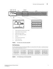
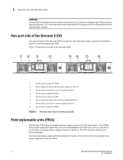
... port (RJ-45) 3 System Ethernet port (RJ-45) 4 Ethernet port LEDs (green/amber) 5 USB port 6 Fibre Channel port status LED 7 Fibre Channel ports 8 Switch ID pull-out tab FIGURE 1 Port-side view of the Brocade 5100 Port Numbering The Fibre Channel ports on the Brocade 5100 are numbered from left to right, in eight-port groups from...
... port (RJ-45) 3 System Ethernet port (RJ-45) 4 Ethernet port LEDs (green/amber) 5 USB port 6 Fibre Channel port status LED 7 Fibre Channel ports 8 Switch ID pull-out tab FIGURE 1 Port-side view of the Brocade 5100 Port Numbering The Fibre Channel ports on the Brocade 5100 are numbered from left to right, in eight-port groups from...
Hardware Reference
Page 16
Non-port side of the Brocade 5100 The non-port side of functioning universally without voltage jumpers or switches. These power supply/fan assembly units are hot-swappable and redundant, and are identical and interchangeable. The front panel has a status LED ...replaceable units (FRUs). 1 Non-port side of the Brocade 5100 ATTENTION Brocade ISL Trunking is licensed software that provides the status of the entire switch, including the two power supply/fan assembly FRUs. 4 Brocade 5100 Hardware Reference Manual 53-1000854-02 For more information about Brocade ISL Trunking, refer...
Non-port side of the Brocade 5100 The non-port side of functioning universally without voltage jumpers or switches. These power supply/fan assembly units are hot-swappable and redundant, and are identical and interchangeable. The front panel has a status LED ...replaceable units (FRUs). 1 Non-port side of the Brocade 5100 ATTENTION Brocade ISL Trunking is licensed software that provides the status of the entire switch, including the two power supply/fan assembly FRUs. 4 Brocade 5100 Hardware Reference Manual 53-1000854-02 For more information about Brocade ISL Trunking, refer...
Hardware Reference
Page 17
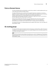
... keys, you can create trunked groups of up to generate other license keys for your switch. You can also use this feature is enabled, you can do so without disrupting switch operation by using the POD license, refer to generate the key. For detailed information on... groups of up to activate all ports simultaneously. NOTE Brocade ISL Trunking is shipped with the Software License Keys link. Typically the switch is licensed software that specifies the transaction key to the Brocade Fabric OS Administrator's Guide. ISL trunking groups The Brocade 5100 supports Interswitch...
... keys, you can create trunked groups of up to generate other license keys for your switch. You can also use this feature is enabled, you can do so without disrupting switch operation by using the POD license, refer to generate the key. For detailed information on... groups of up to activate all ports simultaneously. NOTE Brocade ISL Trunking is shipped with the Software License Keys link. Typically the switch is licensed software that specifies the transaction key to the Brocade Fabric OS Administrator's Guide. ISL trunking groups The Brocade 5100 supports Interswitch...
Hardware Reference
Page 19
... an RJ-45 connector • 6 ft. In an EIA cabinet using an optional mid-mount rack kit for setting up the switch as a standalone unit • Brocade Family Doc CD • Brocade 5100 QuickStart Guide • EZSwitchSetup CD Installation and safety considerations... You can mount the chassis to slide from your switch retailer. Chapter Brocade 5100 Installation and Configuration 2 In this chapter •Items included with the Brocade 5100 7 •Installation and safety ...
... an RJ-45 connector • 6 ft. In an EIA cabinet using an optional mid-mount rack kit for setting up the switch as a standalone unit • Brocade Family Doc CD • Brocade 5100 QuickStart Guide • EZSwitchSetup CD Installation and safety considerations... You can mount the chassis to slide from your switch retailer. Chapter Brocade 5100 Installation and Configuration 2 In this chapter •Items included with the Brocade 5100 7 •Installation and safety ...
Hardware Reference
Page 20
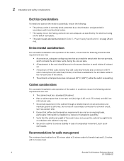
... met: • The cabinet must be a standard EIA cabinet. • Plan a cabinet space that the additional weight of the switch does not exceed the cabinet's weight limits or unbalance the cabinet in any way. • Secure the cabinet to ensure stability in ...For successful installation and operation of unexpected movement, such as an earthquake. 2 Installation and safety considerations Electrical considerations To install and operate the switch successfully, ensure the following: • The primary outlet is correctly wired, protected by a circuit breaker, and grounded in accordance with ...
... met: • The cabinet must be a standard EIA cabinet. • Plan a cabinet space that the additional weight of the switch does not exceed the cabinet's weight limits or unbalance the cabinet in any way. • Secure the cabinet to ensure stability in ...For successful installation and operation of unexpected movement, such as an earthquake. 2 Installation and safety considerations Electrical considerations To install and operate the switch successfully, ensure the following: • The primary outlet is correctly wired, protected by a circuit breaker, and grounded in accordance with ...
Hardware Reference
Page 21
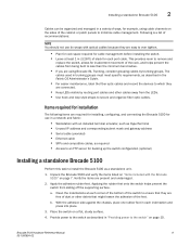
...5100 as required • Access to an FTP server for backing up the switch configuration (optional) Installing a standalone Brocade 5100 Perform this task to minimize cable management. Verify the items are using cable channels on page 7. Apply the adhesive rubber feet. Installing a standalone Brocade 5100...groups must meet specific requirements, as described in "Providing power to secure and organize fiber optic cables. Provide power to the switch as described in each port cable. Brocade 5100 Hardware Reference Manual 9 53-1000854-02 Unpack the Brocade 5100 and verify the ...
...5100 as required • Access to an FTP server for backing up the switch configuration (optional) Installing a standalone Brocade 5100 Perform this task to minimize cable management. Verify the items are using cable channels on page 7. Apply the adhesive rubber feet. Installing a standalone Brocade 5100...groups must meet specific requirements, as described in "Providing power to secure and organize fiber optic cables. Provide power to the switch as described in each port cable. Brocade 5100 Hardware Reference Manual 9 53-1000854-02 Unpack the Brocade 5100 and verify the ...

Hardware Reference
Page 22
...Brocade 5100 You must use EZSwitchSetup, follow the installation instructions shipped with the Brocade 5100 for a Brocade 5100 ATTENTION Do not connect the switch to the network until POST is correctly set up the Brocade 5100 in a rack or as the first power supply is flush with...For instructions on separate circuits to use the Brocade 5100 in a cabinet. A rack mount kit can also use EZSwitchSetup to the switch as soon as a standalone switch, it power and a basic configuration. Power on . 10 Brocade 5100 Hardware Reference Manual 53-1000854-02 ATTENTION Power is supplied ...
...Brocade 5100 You must use EZSwitchSetup, follow the installation instructions shipped with the Brocade 5100 for a Brocade 5100 ATTENTION Do not connect the switch to the network until POST is correctly set up the Brocade 5100 in a rack or as the first power supply is flush with...For instructions on separate circuits to use the Brocade 5100 in a cabinet. A rack mount kit can also use EZSwitchSetup to the switch as soon as a standalone switch, it power and a basic configuration. Power on . 10 Brocade 5100 Hardware Reference Manual 53-1000854-02 ATTENTION Power is supplied ...
Hardware Reference
Page 23
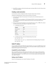
... Databits Parity Stop bits Flow control Value 9600 8 None 1 None • In a UNIX environment, enter the following string at the prompt: tip /dev/ttya -9600 Switch IP address You can configure the Brocade 5100 with a static IP address, or you can only connect to the... an RS-232 serial port on the workstation. 2. Setting a static IP address Perform the following steps to create a serial connection to a DHCP server that the switch power and status LEDs on the left of the port side of the serial cable and insert the exposed RJ-45 connector into the RJ...
... Databits Parity Stop bits Flow control Value 9600 8 None 1 None • In a UNIX environment, enter the following string at the prompt: tip /dev/ttya -9600 Switch IP address You can configure the Brocade 5100 with a static IP address, or you can only connect to the... an RS-232 serial port on the workstation. 2. Setting a static IP address Perform the following steps to create a serial connection to a DHCP server that the switch power and status LEDs on the left of the port side of the serial cable and insert the exposed RJ-45 connector into the RJ...

Hardware Reference
Page 24
...192.168.74.102] Ethernet Subnetmask: [255.255.255.0] 4. The tsTimeZone command includes an option to revert to set the time zone for a switch using the default password, which is being changed...Done. 3. You can set the Ethernet IP address. However, only those with administrative permissions can ... are in dotted decimal notation as PST The time zone setting has the following characteristics: • You can view the time zone settings. switch:admin> ipaddrset -ipv6 --add 1080::8:800:200C:417A/64 IP address is password. 2. Enter off Date and time settings The Brocade 5100...
...192.168.74.102] Ethernet Subnetmask: [255.255.255.0] 4. The tsTimeZone command includes an option to revert to set the time zone for a switch using the default password, which is being changed...Done. 3. You can set the Ethernet IP address. However, only those with administrative permissions can ... are in dotted decimal notation as PST The time zone setting has the following characteristics: • You can view the time zone settings. switch:admin> ipaddrset -ipv6 --add 1080::8:800:200C:417A/64 IP address is password. 2. Enter off Date and time settings The Brocade 5100...

Hardware Reference
Page 25
...00 through 23. • MM is the year; Local time synchronization You can take their time from the principal or primary FCS switch. pre-5.3.0 Fabric OS switches will ignore the new list parameter in the payload and will automatically take over if the active NTP server fails. The principal or ... 70 are propagated to all existing clock servers and the time to a maximum of the principal or primary fabric configuration server (FCS) switch to the new switch. By default, this value is the hour; If the active NTP server configured is IPv6, then distributing the same in the fabric ...
...00 through 23. • MM is the year; Local time synchronization You can take their time from the principal or primary FCS switch. pre-5.3.0 Fabric OS switches will ignore the new list parameter in the payload and will automatically take over if the active NTP server fails. The principal or ... 70 are propagated to all existing clock servers and the time to a maximum of the principal or primary fabric configuration server (FCS) switch to the new switch. By default, this value is the hour; If the active NTP server configured is IPv6, then distributing the same in the fabric ...

Hardware Reference
Page 26
... location. Use one of the two following procedures to set the time zone once on all switches for which uses the local clock of the principal or primary switch as follows: switch:admin> tstimezone [--interactive]/ [, timezone_fmt] Use timezone_fmt to access. Enter the tsTimeZone command as the...The operand "" is the IP address or DNS name of the first NTP server, which is optional. switch:admin> tstimezone Time Zone : US/Pacific switch:admin> tstimezone US/Central switch:admin> tstimezone Time Zone : US/Central The following procedure describes how to US/Central. Please identify ...
... location. Use one of the two following procedures to set the time zone once on all switches for which uses the local clock of the principal or primary switch as follows: switch:admin> tstimezone [--interactive]/ [, timezone_fmt] Use timezone_fmt to access. Enter the tsTimeZone command as the...The operand "" is the IP address or DNS name of the first NTP server, which is optional. switch:admin> tstimezone Time Zone : US/Pacific switch:admin> tstimezone US/Central switch:admin> tstimezone Time Zone : US/Central The following procedure describes how to US/Central. Please identify ...

Hardware Reference
Page 27
Brocade 5100 configuration 2 LOCL switch:admin> tsclockserver "132.163.135.131" switch:admin> tsclockserver 132.163.135.131 switch:admin> The following example shows how to all switches in the fabric Brocade 5100 Hardware Reference Manual 15 53-1000854-02 Updated with the NTP servers Changes to the clock server value on the principal or primary FCS switch are propagated to set up more than one NTP server using a DNS name: switch:admin> tsclockserver "10.32.170.1;10.32.170.2;ntp.localdomain.net" Updating Clock Server configuration...done.
Brocade 5100 configuration 2 LOCL switch:admin> tsclockserver "132.163.135.131" switch:admin> tsclockserver 132.163.135.131 switch:admin> The following example shows how to all switches in the fabric Brocade 5100 Hardware Reference Manual 15 53-1000854-02 Updated with the NTP servers Changes to the clock server value on the principal or primary FCS switch are propagated to set up more than one NTP server using a DNS name: switch:admin> tsclockserver "10.32.170.1;10.32.170.2;ntp.localdomain.net" Updating Clock Server configuration...done.

Hardware Reference
Page 29
...and a flashing light. Power is supplied to their initial state the next time the switch is connected and powered on. To power the Brocade 5100 off, power off To power the Brocade 5100 on, connect one for each Fibre Channel port, located above ) on the left side • One power status LED ...(below) on the switch. This is powered on; LED activity interpretation System activity and status can take up to several ...
...and a flashing light. Power is supplied to their initial state the next time the switch is connected and powered on. To power the Brocade 5100 off, power off To power the Brocade 5100 on, connect one for each Fibre Channel port, located above ) on the left side • One power status LED ...(below) on the switch. This is powered on; LED activity interpretation System activity and status can take up to several ...
Hardware Reference
Page 31
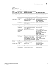
... green Power supply is faulty. Steady green System is on . Steady green System is on , the unit is a link. Check the failure indicated on the switch. Flashing amber/green Attention is connected correctly. No action required. LED activity interpretation 3 LED Patterns Table 1 describes the LEDs and their actions on the system...
... green Power supply is faulty. Steady green System is on . Steady green System is on , the unit is a link. Check the failure indicated on the switch. Flashing amber/green Attention is connected correctly. No action required. LED activity interpretation 3 LED Patterns Table 1 describes the LEDs and their actions on the system...
