
User Guide
Page 1
User's Guide EVGA X58 SLI Motherboard
User's Guide EVGA X58 SLI Motherboard

User Guide
Page 3
EVGA X58 SLI Motherboard Table of Contents User's Guide...1 EVGA X58 SLI Motherboard 1 Before You Begin...8 Parts NOT in the Kit 8 Intentions of the Kit 8 EVGA X58 SLI Motherboard 10 Motherboard Specifications 10 Unpacking and Parts Descriptions 12 Unpacking ...12 Equipment ...12 EVGA X58 SLI Motherboard 14 Hardware Installation 17 Safety Instructions 17 Preparing the Motherboard 18 Installing the CPU 18 Installing the CPU Fan 19 Installing System Memory...
EVGA X58 SLI Motherboard Table of Contents User's Guide...1 EVGA X58 SLI Motherboard 1 Before You Begin...8 Parts NOT in the Kit 8 Intentions of the Kit 8 EVGA X58 SLI Motherboard 10 Motherboard Specifications 10 Unpacking and Parts Descriptions 12 Unpacking ...12 Equipment ...12 EVGA X58 SLI Motherboard 14 Hardware Installation 17 Safety Instructions 17 Preparing the Motherboard 18 Installing the CPU 18 Installing the CPU Fan 19 Installing System Memory...

User Guide
Page 5
EVGA X58 SLI Motherboard Hard Disk Boot Priority 44 CD-ROM Device Priority 44 First/Second/Third Boot Device 44 Boot Other Device 45 Boot Up NumLock Status 45 ...
EVGA X58 SLI Motherboard Hard Disk Boot Priority 44 CD-ROM Device Priority 44 First/Second/Third Boot Device 44 Boot Other Device 45 Boot Up NumLock Status 45 ...

User Guide
Page 6
POST Codes for the EVGA X58 SLI Motherboard 66 EVGA Glossary of Terms 74 INT Pin 1/2/3/4/5/6/7/8 Assignment 55 Maximum Payload Size 55 PC Health Status Menu 56 SmartFan Function 57 Frequency/Voltage Control Menu 58 Memory Feature 59 Voltage Control Menu 60 EVGA VDroop control 60 CPU VCore...60 CPU VTT Voltage 60 CPU PLL Vcore 60...
POST Codes for the EVGA X58 SLI Motherboard 66 EVGA Glossary of Terms 74 INT Pin 1/2/3/4/5/6/7/8 Assignment 55 Maximum Payload Size 55 PC Health Status Menu 56 SmartFan Function 57 Frequency/Voltage Control Menu 58 Memory Feature 59 Voltage Control Menu 60 EVGA VDroop control 60 CPU VCore...60 CPU VTT Voltage 60 CPU PLL Vcore 60...
User Guide
Page 7
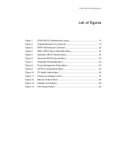
Figure 10. Figure 2. Figure 9. Figure 12. Figure 6. Figure 14. Figure 4. Figure 7. Figure 3. Figure 11. Figure 8. EVGA X58 SLI Motherboard Layout 14 Chassis Backpanel Connectors 15 PWR1 Motherboard Connector 22 BIOS CMOS Setup Utility Main Menu 36 Standard CMOS Features Menu 38 Advanced BIOS Features Menu 42 Integrated Peripherals Menu 44 Power Management... 52 PC Health Status Menu 54 Frequency/Voltage Control 57 Memory Feature Menu 58 Voltage Control Menu 60 CPU Feature Menu 62 Figure 13. EVGA X58 SLI Motherboard List of Figures Figure 1. Figure 5.
Figure 10. Figure 2. Figure 9. Figure 12. Figure 6. Figure 14. Figure 4. Figure 7. Figure 3. Figure 11. Figure 8. EVGA X58 SLI Motherboard Layout 14 Chassis Backpanel Connectors 15 PWR1 Motherboard Connector 22 BIOS CMOS Setup Utility Main Menu 36 Standard CMOS Features Menu 38 Advanced BIOS Features Menu 42 Integrated Peripherals Menu 44 Power Management... 52 PC Health Status Menu 54 Frequency/Voltage Control 57 Memory Feature Menu 58 Voltage Control Menu 60 CPU Feature Menu 62 Figure 13. EVGA X58 SLI Motherboard List of Figures Figure 1. Figure 5.
User Guide
Page 8
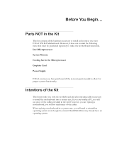
...all connecting cables necessary to allow for the Microprocessor Graphics Card Power Supply EVGA assumes you will not need to install and connect your new EVGA X58 SLI Motherboard. Parts NOT in the kit. When replacing a motherboard in a system case, you will need many of the cables provided... in the Kit This kit contains all the necessary parts needed to install the motherboard into a system case. If however...
...all connecting cables necessary to allow for the Microprocessor Graphics Card Power Supply EVGA assumes you will not need to install and connect your new EVGA X58 SLI Motherboard. Parts NOT in the kit. When replacing a motherboard in a system case, you will need many of the cables provided... in the Kit This kit contains all the necessary parts needed to install the motherboard into a system case. If however...

User Guide
Page 9
EVGA X58 SLI Motherboard
EVGA X58 SLI Motherboard

User Guide
Page 10
... enthusiast performance and when combined with two or three SLI-Ready NVIDIA® GeForce® graphics cards, you for enhanced system performance. Motherboard Specifications Size ATX form factor of DDR3 memory. EVGA X58 SLI Motherboard Thank you get innovative NVIDIA® SLI® technology for purchasing the EVGA X58 SLI Motherboard. Officially supports up to 12GBs of 12 inch x 9.6 inch Microprocessor...
... enthusiast performance and when combined with two or three SLI-Ready NVIDIA® GeForce® graphics cards, you for enhanced system performance. Motherboard Specifications Size ATX form factor of DDR3 memory. EVGA X58 SLI Motherboard Thank you get innovative NVIDIA® SLI® technology for purchasing the EVGA X58 SLI Motherboard. Officially supports up to 12GBs of 12 inch x 9.6 inch Microprocessor...

User Guide
Page 11
... Two PCI slots One PCI Express x1 slot Three PCI Express x8/x16 slots depends on suspend), S3 (suspend to RAM), S4 (Suspend to disk - EVGA X58 SLI Motherboard Nine(9) onboard Serial ATA II + one(1) eSATA II 300MBps data transfer rate Six Serial ATA II connectors from south bridge with support for RAID 0, RAID...
... Two PCI slots One PCI Express x1 slot Three PCI Express x8/x16 slots depends on suspend), S3 (suspend to RAM), S4 (Suspend to disk - EVGA X58 SLI Motherboard Nine(9) onboard Serial ATA II + one(1) eSATA II 300MBps data transfer rate Six Serial ATA II connectors from south bridge with support for RAID 0, RAID...

User Guide
Page 12
...Helps to quickly and visually guide you may not need many of the motherboard. 1 - Unpacking and Parts Descriptions Unpacking The EVGA X58 SLI Motherboard comes with the EVGA X58 SLI Motherboard. If replacing a motherboard, you through the hardware installation of these cables. All parts shipped in ...The following accessories are RoHS-compliant (lead-free) parts. The EVGA X58 SLI Motherboard This PCI Express motherboard contains the Intel X58 and ICH10R chipset and is SLI-ready for adding a motherboard to block radio frequency transmissions, protect internal components from dust, ...
...Helps to quickly and visually guide you may not need many of the motherboard. 1 - Unpacking and Parts Descriptions Unpacking The EVGA X58 SLI Motherboard comes with the EVGA X58 SLI Motherboard. If replacing a motherboard, you through the hardware installation of these cables. All parts shipped in ...The following accessories are RoHS-compliant (lead-free) parts. The EVGA X58 SLI Motherboard This PCI Express motherboard contains the Intel X58 and ICH10R chipset and is SLI-ready for adding a motherboard to block radio frequency transmissions, protect internal components from dust, ...

User Guide
Page 13
...- 4-Port USB 2.0 Bracket Provides four additional USB ports to the motherboard. 1 - IEEE1394a (Firewire) Bracket Provides one connects a single drive to either the front or back panels of the chassis. 6 - EVGA X58 SLI Motherboard 3 - 2-Port SATA Power Cables Allows a Molex power connector to ...adapt to setup the motherboard. IDE Data Cable Passes data between the IDE connection on the motherboard and IDE device. 1 - 2-Way SLI Bridge Bridges two (2) graphic cards together...
...- 4-Port USB 2.0 Bracket Provides four additional USB ports to the motherboard. 1 - IEEE1394a (Firewire) Bracket Provides one connects a single drive to either the front or back panels of the chassis. 6 - EVGA X58 SLI Motherboard 3 - 2-Port SATA Power Cables Allows a Molex power connector to ...adapt to setup the motherboard. IDE Data Cable Passes data between the IDE connection on the motherboard and IDE device. 1 - 2-Way SLI Bridge Bridges two (2) graphic cards together...

User Guide
Page 14
EVGA X58 SLI Motherboard The EVGA X58 SLI Motherboard with the Intel X58 and ICH10R chipset is a PCI Express, SLI-ready motherboard. Figure 1 shows the motherboard and Figures 2 shows the back panel connectors.
EVGA X58 SLI Motherboard The EVGA X58 SLI Motherboard with the Intel X58 and ICH10R chipset is a PCI Express, SLI-ready motherboard. Figure 1 shows the motherboard and Figures 2 shows the back panel connectors.

User Guide
Page 17
The topics covered in this section are: Preparing the motherboard Installing the CPU Installing the CPU fan Installing the memory Installing the motherboard Connecting cables Safety Instructions To reduce the risk of the motherboard. Hardware Installation This section will guide you through the installation of fire, electric shock, and injury, always follow basic safety precautions. Remember to remove power from your computer by disconnecting the AC main source before removing or installing any equipment from/to the computer chassis.
The topics covered in this section are: Preparing the motherboard Installing the CPU Installing the CPU fan Installing the memory Installing the motherboard Connecting cables Safety Instructions To reduce the risk of the motherboard. Hardware Installation This section will guide you through the installation of fire, electric shock, and injury, always follow basic safety precautions. Remember to remove power from your computer by disconnecting the AC main source before removing or installing any equipment from/to the computer chassis.
User Guide
Page 18
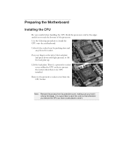
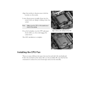
Use the following procedure to install the CPU onto the motherboard: Unhook the socket lever by pushing down with light pressure to save the cover so that whenever you remove the CPU you hold it . There ... protective socket cover from the CPU Socket. Hold the processor only by the edges. Lift the load plate. It is no CPU installed. Preparing the Motherboard Installing the CPU Be very careful when handling the CPU.
Use the following procedure to install the CPU onto the motherboard: Unhook the socket lever by pushing down with light pressure to save the cover so that whenever you remove the CPU you hold it . There ... protective socket cover from the CPU Socket. Hold the processor only by the edges. Lift the load plate. It is no CPU installed. Preparing the Motherboard Installing the CPU Be very careful when handling the CPU.
User Guide
Page 19
... Fan There are many different fan types that can be used with you close and engage the socket lever. Be sure that came with this motherboard. Follow the instruction that the fan orientation is complete. Align notches with notches on the socket. The CPU installation is correct for your chassis type...
... Fan There are many different fan types that can be used with you close and engage the socket lever. Be sure that came with this motherboard. Follow the instruction that the fan orientation is complete. Align notches with notches on the socket. The CPU installation is correct for your chassis type...

User Guide
Page 20
... DIMMs. Note that there is installed properly. 1. Three DIMMs: If using 3 DIMMs (Triple Channel), install into : DIMM slots 2, 1, 4, and 3. Installing System Memory (DIMMs) Your new motherboard has six 240-pin slots for the location of the memory slots.) One DIMM: If using 1 DIMM (Single Channel), install into : DIMM slots 1 and 3. If...
... DIMMs. Note that there is installed properly. 1. Three DIMMs: If using 3 DIMMs (Triple Channel), install into : DIMM slots 2, 1, 4, and 3. Installing System Memory (DIMMs) Your new motherboard has six 240-pin slots for the location of the memory slots.) One DIMM: If using 1 DIMM (Single Channel), install into : DIMM slots 1 and 3. If...

User Guide
Page 21
...assembly has enough clearance for the expansion cards. Use the following procedure to secure the motherboard first. Installing the I/O Shield The motherboard kit comes with an empty system case. Installing the Motherboard The sequence of the chassis. Determine if it fits securely. It is normally easier ...the connections prior to this step or to block radio frequency transmissions, protects internal components from the inside of installing the motherboard into the chassis. This will depend on the covers. Also make sure it would need to obtain the proper size from...
...assembly has enough clearance for the expansion cards. Use the following procedure to secure the motherboard first. Installing the I/O Shield The motherboard kit comes with an empty system case. Installing the Motherboard The sequence of the chassis. Determine if it fits securely. It is normally easier ...the connections prior to this step or to block radio frequency transmissions, protects internal components from the inside of installing the motherboard into the chassis. This will depend on the covers. Also make sure it would need to obtain the proper size from...
User Guide
Page 22
... to prevent the possibility of nine (9) spacers and screws. 1. Connecting Cables This section takes you through all the necessary connections on the motherboard, it is recommended that you remove that do not align with the studs/spacers. If there are studs that stud to secure the... motherboard using a minimum of a short circuit. Align the mounting holes with a mounting hole on the motherboard. This will include: Power Connections 24-pin ATX power (PW1) 8-pin ATX 12V power (PW12)...
... to prevent the possibility of nine (9) spacers and screws. 1. Connecting Cables This section takes you through all the necessary connections on the motherboard, it is recommended that you remove that do not align with the studs/spacers. If there are studs that stud to secure the... motherboard using a minimum of a short circuit. Align the mounting holes with a mounting hole on the motherboard. This will include: Power Connections 24-pin ATX power (PW1) 8-pin ATX 12V power (PW12)...
User Guide
Page 23
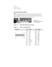
... Table 1. Make sure that the power supply cable and pins are properly aligned with the connector on the motherboard. PW1 Pin Assignments Connector 1 13 Pin Signal 1 +3.3V 12 2 +3.3V 3 GND 4 +5V 5 GND 6 +5V 24 7 GND 8 PWROK 9 +5V_AUX 10 +12V 11 +12V 12 +3.3V Pin ...
... Table 1. Make sure that the power supply cable and pins are properly aligned with the connector on the motherboard. PW1 Pin Assignments Connector 1 13 Pin Signal 1 +3.3V 12 2 +3.3V 3 GND 4 +5V 5 GND 6 +5V 24 7 GND 8 PWROK 9 +5V_AUX 10 +12V 11 +12V 12 +3.3V Pin ...

User Guide
Page 24
Align the pins to a slave device. Motherboard Edge IDE Connector Connect the grey connector to the connector and press firmly until seated. 12V Ground Connecting IDE Hard Disk Drives The IDE connector ... drive using any other IDE transfer protocol are attached to the same cable, the maximum transfer rate between the drives may be reduced to the motherboard. 2. If you install two hard disk drives, you must configure the second drive as a slave device by setting its jumper accordingly. Connect the blue connector...
Align the pins to a slave device. Motherboard Edge IDE Connector Connect the grey connector to the connector and press firmly until seated. 12V Ground Connecting IDE Hard Disk Drives The IDE connector ... drive using any other IDE transfer protocol are attached to the same cable, the maximum transfer rate between the drives may be reduced to the motherboard. 2. If you install two hard disk drives, you must configure the second drive as a slave device by setting its jumper accordingly. Connect the blue connector...