
User Manual
Page 2
... appear slightly different from time to time in the contents hereof without the prior written permission from any warranties, merchantability, or fitness for updates. COPYRIGHT Copyright Edimax Technology Co., Ltd. Edimax Technology Co., Ltd. No part of this manual are subject to the user manual on the CD-ROM. The product you have purchased and the setup screen may...
... appear slightly different from time to time in the contents hereof without the prior written permission from any warranties, merchantability, or fitness for updates. COPYRIGHT Copyright Edimax Technology Co., Ltd. Edimax Technology Co., Ltd. No part of this manual are subject to the user manual on the CD-ROM. The product you have purchased and the setup screen may...

User Manual
Page 3
... Chapter 1: Introduction ...3 1.1 Product Features...3 1.2 Application ...3 1.3 Compatibility...4 1.4 System Requirements ...4 Chapter 2: Interfaces ...5 2.1 LEDs...5 2.2 Button ...5 2.3 Gigabit Ethernet Port ...6 Chapter 3:Utility Software Installation ...7 3.1 Win 8 ...7 3.2 Win XP/Vista / 7 ...14 Chapter 4: Using the Utility Software ...20 4.1 Main Tab ...20 4.2 Diagnostics Tab ...21 4.3 About Tab...22 Chapter 5: Group Button ...23 5.1 Forming a HomePlug AV Logical Network 23 5.2 Joining a Network ...24 5.3 Leaving a Network & Joining another Network 25 Chapter 6: Troubleshooting ...26 2
... Chapter 1: Introduction ...3 1.1 Product Features...3 1.2 Application ...3 1.3 Compatibility...4 1.4 System Requirements ...4 Chapter 2: Interfaces ...5 2.1 LEDs...5 2.2 Button ...5 2.3 Gigabit Ethernet Port ...6 Chapter 3:Utility Software Installation ...7 3.1 Win 8 ...7 3.2 Win XP/Vista / 7 ...14 Chapter 4: Using the Utility Software ...20 4.1 Main Tab ...20 4.2 Diagnostics Tab ...21 4.3 About Tab...22 Chapter 5: Group Button ...23 5.1 Forming a HomePlug AV Logical Network 23 5.2 Joining a Network ...24 5.3 Leaving a Network & Joining another Network 25 Chapter 6: Troubleshooting ...26 2

User Manual
Page 4
... a home's electrical circuit for better performance through walls or across floors • Built-in QoS assures the quality of bandwidth sensitive applications such as voice, video and online games • Supports IGMP managed multicast IP transmission, optimizing IPTV streaming • Compatible with all AV500 & AV200 Powerline adapters (HomePlug AV) • Integrated power socket with noise filter 1.2 Application High-definition...
... a home's electrical circuit for better performance through walls or across floors • Built-in QoS assures the quality of bandwidth sensitive applications such as voice, video and online games • Supports IGMP managed multicast IP transmission, optimizing IPTV streaming • Compatible with all AV500 & AV200 Powerline adapters (HomePlug AV) • Integrated power socket with noise filter 1.2 Application High-definition...
User Manual
Page 5
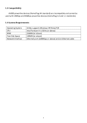
1.3 Compatibility AV600 powerline devices (HomePlug AV standard) are incompatible and cannot be used with 14Mbps and 85Mbps powerline devices (HomePlug 1.0 and 1.1 standards). 1.4 System Requirements Operating System CPU RAM Free Disk Space Network Interface Utility supports Windows XP/Vista/7/8 Intel Pentium III 1.0GHz (or above) 256MB (or above) 100MB (or above) Ethernet port (100Mbps or above) and an Ethernet cable 4
1.3 Compatibility AV600 powerline devices (HomePlug AV standard) are incompatible and cannot be used with 14Mbps and 85Mbps powerline devices (HomePlug 1.0 and 1.1 standards). 1.4 System Requirements Operating System CPU RAM Free Disk Space Network Interface Utility supports Windows XP/Vista/7/8 Intel Pentium III 1.0GHz (or above) 256MB (or above) 100MB (or above) Ethernet port (100Mbps or above) and an Ethernet cable 4

User Manual
Page 6
... indicator turns blinks quickly to 5 Chapter 2: Interfaces 2.1 LEDs LED LAN1-3 Status Green Blinking Off Green PLC Off Green PWR Off Description LAN port connected LAN activity (transferring data) LAN port not connected The green indicator turns on Powered off 2.2 Button Interface Description Integrated The integrated electrical socket enables additional Power Socket terminal devices or multiple socket to be connected to indicate data is detecting a powerline link. No other PLC device detected Powered on...
... indicator turns blinks quickly to 5 Chapter 2: Interfaces 2.1 LEDs LED LAN1-3 Status Green Blinking Off Green PLC Off Green PWR Off Description LAN port connected LAN activity (transferring data) LAN port not connected The green indicator turns on Powered off 2.2 Button Interface Description Integrated The integrated electrical socket enables additional Power Socket terminal devices or multiple socket to be connected to indicate data is detecting a powerline link. No other PLC device detected Powered on...

User Manual
Page 7
Ethernet Port Group Reset the adapter, just as a normal wall socket would. This is a Gigabit Ethernet port for less than 3 seconds). Creates an encrypted powerline network group automatically (press the button for connecting to a computer or other devices with a network port. Restores the powerline adapter to a router, a computer, or any network device via this Gigabit Ethernet port. 6 Leaves an encrypted powerline network group (press the button for 8~12 seconds). 2.3 Gigabit Ethernet Port You...
Ethernet Port Group Reset the adapter, just as a normal wall socket would. This is a Gigabit Ethernet port for less than 3 seconds). Creates an encrypted powerline network group automatically (press the button for connecting to a computer or other devices with a network port. Restores the powerline adapter to a router, a computer, or any network device via this Gigabit Ethernet port. 6 Leaves an encrypted powerline network group (press the button for 8~12 seconds). 2.3 Gigabit Ethernet Port You...

User Manual
Page 8
When the following EZmax Wizard appears, select your CD-ROM drive. Chapter 3:Utility Software Installation 3.1 Win 8 Step 1 Before installing the utility software, make sure that no other utility software is installed on your computer. If any other powerline utility is installed, uninstall it and reboot the computer. Step 3 Then click "Setup Utility". 7 Step 2 Insert the CD into your model.
When the following EZmax Wizard appears, select your CD-ROM drive. Chapter 3:Utility Software Installation 3.1 Win 8 Step 1 Before installing the utility software, make sure that no other utility software is installed on your computer. If any other powerline utility is installed, uninstall it and reboot the computer. Step 3 Then click "Setup Utility". 7 Step 2 Insert the CD into your model.

User Manual
Page 9
Step 6 Then click "WinPcap_4_1_2". Step 4 Click right button on WinPCap4.1.2 then click "Properties". Step 5 Click Compatibility tab and check "Run this program in compatibility mode for:", then select Windows 7, then click "Apply". The wizard will guide you through the setup process. 8
Step 6 Then click "WinPcap_4_1_2". Step 4 Click right button on WinPCap4.1.2 then click "Properties". Step 5 Click Compatibility tab and check "Run this program in compatibility mode for:", then select Windows 7, then click "Apply". The wizard will guide you through the setup process. 8
User Manual
Page 14
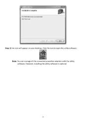
Note: You can manage all the connected powerline adapters with the utility software. Click the icon to open the utility software. However, installing the utility software is optional. 13 Step 12 An icon will appear on your desktop.
Note: You can manage all the connected powerline adapters with the utility software. Click the icon to open the utility software. However, installing the utility software is optional. 13 Step 12 An icon will appear on your desktop.

User Manual
Page 15
3.2 Win XP/Vista / 7 Step 1 Before installing the utility software, make sure that no other utility software is installed on your computer. If any other powerline utility is installed, uninstall it and reboot the computer. Step 2 Insert the CD into your model. When the following EZmax Wizard appears, select your CD-ROM drive. Step 3 Then click "Setup Utility". 14
3.2 Win XP/Vista / 7 Step 1 Before installing the utility software, make sure that no other utility software is installed on your computer. If any other powerline utility is installed, uninstall it and reboot the computer. Step 2 Insert the CD into your model. When the following EZmax Wizard appears, select your CD-ROM drive. Step 3 Then click "Setup Utility". 14
User Manual
Page 16
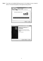
Step 4 If you through the setup process. 15 The wizard will guide you have not installed WinPcap version 4.1.2 (or higher) on your computer before.
Step 4 If you through the setup process. 15 The wizard will guide you have not installed WinPcap version 4.1.2 (or higher) on your computer before.

User Manual
Page 18
Step 5 When the "Edimax PowerLine Utility" setup wizard appears, click "Next" to continue. 17 Step 6 In the "License Agreement" screen, please select "I Agree" and then click "Next" to continue.
Step 5 When the "Edimax PowerLine Utility" setup wizard appears, click "Next" to continue. 17 Step 6 In the "License Agreement" screen, please select "I Agree" and then click "Next" to continue.
User Manual
Page 20
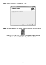
However, installing the utility software is complete, click "Close". Note: You can manage all the connected powerline adapters with the utility software. Click the icon to open the utility software. Step 9 After the installation is optional. 19 Step 10 An icon will appear on your desktop.
However, installing the utility software is complete, click "Close". Note: You can manage all the connected powerline adapters with the utility software. Click the icon to open the utility software. Step 9 After the installation is optional. 19 Step 10 An icon will appear on your desktop.

User Manual
Page 21
The upper panel displays local powerline adapters. By default, this column is blank. By default, the utility automatically scans every few seconds. 20 Click "Scan" and the utility software will perform an immediate scan of powerline adapters connected to rename the device. Set Name Enter Password Scan Select a device and click "Set Name" to the network. The lower panel displays remote powerline adapters in the network. Chapter 4: Using the Utility Software 4.1 Main Tab...
The upper panel displays local powerline adapters. By default, this column is blank. By default, the utility automatically scans every few seconds. 20 Click "Scan" and the utility software will perform an immediate scan of powerline adapters connected to rename the device. Set Name Enter Password Scan Select a device and click "Set Name" to the network. The lower panel displays remote powerline adapters in the network. Chapter 4: Using the Utility Software 4.1 Main Tab...

User Manual
Page 22
The upper panel displays technical data concerning the software and hardware on the host computer and the lower panel displays the history of all remote devices. 21 4.2 Diagnostics Tab The "Diagnostics" tab displays the system information and history of all remote devices.
The upper panel displays technical data concerning the software and hardware on the host computer and the lower panel displays the history of all remote devices. 21 4.2 Diagnostics Tab The "Diagnostics" tab displays the system information and history of all remote devices.

User Manual
Page 24
... the Power LED starts blinking on adapter A, press the "Group" button on adapter A for less than 3 seconds. The Power LED will start to blink. Step 3 Wait for less than 3 seconds. Chapter 5: Group Button This section demonstrates how to add or remove devices from a HomePlug AV network with the "Group" button. 5.1 Forming a HomePlug AV Logical Network When two devices with different group keys are connected to the same powerline and...
... the Power LED starts blinking on adapter A, press the "Group" button on adapter A for less than 3 seconds. The Power LED will start to blink. Step 3 Wait for less than 3 seconds. Chapter 5: Group Button This section demonstrates how to add or remove devices from a HomePlug AV network with the "Group" button. 5.1 Forming a HomePlug AV Logical Network When two devices with different group keys are connected to the same powerline and...

User Manual
Page 25
Step 2 Within 120 seconds after the Power LED starts blinking on adapter A or B, press the "Group" button on an adapter in the existing network (adapter A or B) for less than 3 seconds. The Power LED will start to be established. 24 Step 3 Wait for the connection to blink. 5.2 Joining a Network If you want to add a new powerline device to an existing network, follow the following procedures: Step 1 Press the "Group" button on the new adapter (adapter C) for at least 3 seconds.
Step 2 Within 120 seconds after the Power LED starts blinking on adapter A or B, press the "Group" button on an adapter in the existing network (adapter A or B) for less than 3 seconds. The Power LED will start to be established. 24 Step 3 Wait for the connection to blink. 5.2 Joining a Network If you want to add a new powerline device to an existing network, follow the following procedures: Step 1 Press the "Group" button on the new adapter (adapter C) for at least 3 seconds.

User Manual
Page 26
... the connection to be removed (adapter B) for at least 3 seconds. Step 4 Within 120 seconds after the Power LED starts blinking on adapter D, press the "Group" button on the adapter to be established. 25 5.3 Leaving a Network & Joining another Network If you want to remove a powerline device from an existing network and add it to another network (adapter D) for less than 3 seconds. Step 2 Wait for adapter B to blink. The Power LED will start...
... the connection to be removed (adapter B) for at least 3 seconds. Step 4 Within 120 seconds after the Power LED starts blinking on adapter D, press the "Group" button on the adapter to be established. 25 5.3 Leaving a Network & Joining another Network If you want to remove a powerline device from an existing network and add it to another network (adapter D) for less than 3 seconds. Step 2 Wait for adapter B to blink. The Power LED will start...
User Manual
Page 27
.... This powerline adapter should not be used in again. Use a pin to hold the reset button down for 2 seconds on GFI protected electric outlets, as some outlets will reset and attempt to establish a connection using factory default settings. Try plugging the powerline adapter into an adjacent electric outlet. Powerline adapters work better when plugged directly into an electric outlet. Using a power strip or surge protector may not be able to establish a connection across different circuit breaker boxes by...
.... This powerline adapter should not be used in again. Use a pin to hold the reset button down for 2 seconds on GFI protected electric outlets, as some outlets will reset and attempt to establish a connection using factory default settings. Try plugging the powerline adapter into an adjacent electric outlet. Powerline adapters work better when plugged directly into an electric outlet. Using a power strip or surge protector may not be able to establish a connection across different circuit breaker boxes by...

User Manual
Page 28
... for Use The ETSI version of April 8, 2000. However, there is restricted for use in the application for an uncontrolled environment. Reorient or relocate the receiving antenna. 2. Connect the equipment into an outlet on a circuit different from that interference will not occur in a residential installation. Federal Communications Commission (FCC) Radiation Exposure Statement This equipment complies with the specific antenna...
... for Use The ETSI version of April 8, 2000. However, there is restricted for use in the application for an uncontrolled environment. Reorient or relocate the receiving antenna. 2. Connect the equipment into an outlet on a circuit different from that interference will not occur in a residential installation. Federal Communications Commission (FCC) Radiation Exposure Statement This equipment complies with the specific antenna...


