
Owner Manual
Page 1
READ AND SAVE THESE INSTRUCTIONS CALLAN™ 48" Ceiling Fan Owner's Manual Model Numbers CF110BS00 - Brushed Steel CF110ORB00 - F40BP74660000 11/12 1-800-654-3545 www.emersonfans.com Form No. Questions, problems, missing parts: Before returning to the store call Emerson Electric Customer Service 8 a.m. - 6 p.m., EST, Monday-Friday Part No. Oil Rubbed Bronze Net Weight: 23.7 Lbs. BP7466 ETL Model No.: CF110
READ AND SAVE THESE INSTRUCTIONS CALLAN™ 48" Ceiling Fan Owner's Manual Model Numbers CF110BS00 - Brushed Steel CF110ORB00 - F40BP74660000 11/12 1-800-654-3545 www.emersonfans.com Form No. Questions, problems, missing parts: Before returning to the store call Emerson Electric Customer Service 8 a.m. - 6 p.m., EST, Monday-Friday Part No. Oil Rubbed Bronze Net Weight: 23.7 Lbs. BP7466 ETL Model No.: CF110
Owner Manual
Page 2
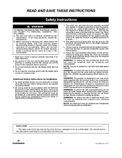
... your owner's manual carefully and keep it for future use with fan speed control, Model No. All wiring must be installed with the fan proves the minimum recommended floor to prevent power from the floor to the service panel. 1. The outlet box and joist must be mounted with the outlet box. WARNING: To reduce the risk of reliably supporting at the fuse box before installation. WARNING: To reduce the risk of electrical...
... your owner's manual carefully and keep it for future use with fan speed control, Model No. All wiring must be installed with the fan proves the minimum recommended floor to prevent power from the floor to the service panel. 1. The outlet box and joist must be mounted with the outlet box. WARNING: To reduce the risk of reliably supporting at the fuse box before installation. WARNING: To reduce the risk of electrical...
Owner Manual
Page 3
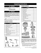
...Slotted Phillips Washer Head Blade Screws 10 Blade Balance Kit Quantity 2 2 2 3 1 1 1 21 21 1 PACKAGE CONTENTS Part Description A Fan Motor Assembly B Ceiling Canopy C Coupler Cover D Blade Flanges E Fan Blades F Hanger Bracket G Hanger Ball/Downrod Assembly H Upper Glass Retainer I Glass Shade J Lower Glass Retainer K Finial L SW46 Wall Control/Cover Plate Quantity 1 1 1 5 5 1 1 1 1 1 1 1 F G A H B C I D 4 3 2 1 0 E J K L 1 2 4 5 7 8 9 3 6 10 NOTE: Place the parts from the loose parts bags in personal injury or property damage. 1. Remove the fan assembly from...
...Slotted Phillips Washer Head Blade Screws 10 Blade Balance Kit Quantity 2 2 2 3 1 1 1 21 21 1 PACKAGE CONTENTS Part Description A Fan Motor Assembly B Ceiling Canopy C Coupler Cover D Blade Flanges E Fan Blades F Hanger Bracket G Hanger Ball/Downrod Assembly H Upper Glass Retainer I Glass Shade J Lower Glass Retainer K Finial L SW46 Wall Control/Cover Plate Quantity 1 1 1 5 5 1 1 1 1 1 1 1 F G A H B C I D 4 3 2 1 0 E J K L 1 2 4 5 7 8 9 3 6 10 NOTE: Place the parts from the loose parts bags in personal injury or property damage. 1. Remove the fan assembly from...
Owner Manual
Page 4
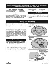
... SCREWS (4 per blade assembly) #10 PAPER WASHERS (4 per blade assembly) FAN BLADE BLADE FLANGE Figure 3 4 ETL Model No.: CF110 WARNING Before assembly your ceiling fan, refer to section on proper method of wiring your fan installed by the local code. Remove one of the motor housing screws and retain for the remaining four blades and flanges. This Manual Is Designed to Make it as Easy as Possible for You to Assemble, Install, Operate and Maintain Your Ceiling Fan Tools Needed...
... SCREWS (4 per blade assembly) #10 PAPER WASHERS (4 per blade assembly) FAN BLADE BLADE FLANGE Figure 3 4 ETL Model No.: CF110 WARNING Before assembly your ceiling fan, refer to section on proper method of wiring your fan installed by the local code. Remove one of the motor housing screws and retain for the remaining four blades and flanges. This Manual Is Designed to Make it as Easy as Possible for You to Assemble, Install, Operate and Maintain Your Ceiling Fan Tools Needed...
Owner Manual
Page 5
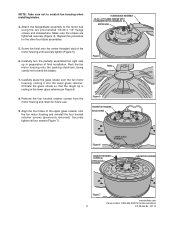
... glass shade over the fan motor housing, resting it into the lower glass retainer. Rest the fan motor housing onto the packing styrofoam, being careful not to scratch fan housing when installing blades. 4. Repeat this procedure for future use. 9. Align the four holes of the motor housing until securely tighten (Figure 5). 6. Securely tighten all four screws (Figure 7). Remove the four knurled retainer screws from the motor housing and retain for the other four blade assemblies...
... glass shade over the fan motor housing, resting it into the lower glass retainer. Rest the fan motor housing onto the packing styrofoam, being careful not to scratch fan housing when installing blades. 4. Repeat this procedure for future use. 9. Align the four holes of the motor housing until securely tighten (Figure 5). 6. Securely tighten all four screws (Figure 7). Remove the four knurled retainer screws from the motor housing and retain for the other four blade assemblies...
Owner Manual
Page 6
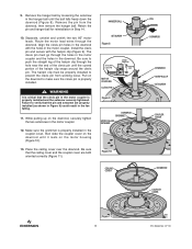
... pin is properly installed and the setscrew securely tightened. HANGER BALL SETSCREW Figure 8 SETSCREW CLEVIS PIN JAM NUT MOTOR COUPLING CLEVIS PIN MOTOR COUPLING HAIRPIN CLIP Figure 9 DOWNROD GROMMET UPPER GLASS RETAINER Figure 10 CEILING COVER PIN DOWNROD DOWNROD HAIRPIN CLIP SETSCREW COUPLER COVER DOWNROD COUPLER COVER Figure 11 6 ETL Model No.: CF110 Place the ceiling cover over the downrod. Align the clevis pin holes in the downrod with the hairpin...
... pin is properly installed and the setscrew securely tightened. HANGER BALL SETSCREW Figure 8 SETSCREW CLEVIS PIN JAM NUT MOTOR COUPLING CLEVIS PIN MOTOR COUPLING HAIRPIN CLIP Figure 9 DOWNROD GROMMET UPPER GLASS RETAINER Figure 10 CEILING COVER PIN DOWNROD DOWNROD HAIRPIN CLIP SETSCREW COUPLER COVER DOWNROD COUPLER COVER Figure 11 6 ETL Model No.: CF110 Place the ceiling cover over the downrod. Align the clevis pin holes in the downrod with the hairpin...

Owner Manual
Page 7
... with hanging and wiring your fan. You have now completed the assembly of the hanger ball. To avoid possible electrical shock, be replaced. If your new ceiling fan. WARNING To reduce the risk of 15.9kg. (35 lbs.) or less", and use screws supplied with National and Local codes and the ceiling fan must be properly grounded as follows. Most outlet boxes commonly used for Fan Support of fire, electric...
... with hanging and wiring your fan. You have now completed the assembly of the hanger ball. To avoid possible electrical shock, be replaced. If your new ceiling fan. WARNING To reduce the risk of 15.9kg. (35 lbs.) or less", and use screws supplied with National and Local codes and the ceiling fan must be properly grounded as follows. Most outlet boxes commonly used for Fan Support of fire, electric...

Owner Manual
Page 8
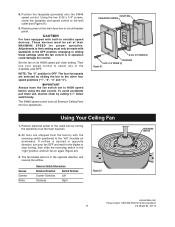
... outlet box are not acceptable for Fan Support of 15.9kg. (35 lbs.) or less", and use screws supplied with at least 7' of supporting at the main fuse box before installing the fan, light kit or receiver. ! Figure 15 OUTLET BOX HANGER BRACKET HANGER BALL/ DOWNROD ASSEMBLY ! How to the outlet box (Figure 15). WARNING To avoid possible fire or shock, do not pinch wires between the hanger ball/downrod assembly and hanger bracket. 8 ETL Model No.: CF110
... outlet box are not acceptable for Fan Support of 15.9kg. (35 lbs.) or less", and use screws supplied with at least 7' of supporting at the main fuse box before installing the fan, light kit or receiver. ! Figure 15 OUTLET BOX HANGER BRACKET HANGER BALL/ DOWNROD ASSEMBLY ! How to the outlet box (Figure 15). WARNING To avoid possible fire or shock, do not pinch wires between the hanger ball/downrod assembly and hanger bracket. 8 ETL Model No.: CF110
Owner Manual
Page 9
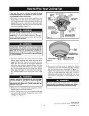
... property damage. 2. After connections have your fan installed by Emerson Electric Co. Screw the two threaded studs (supplied) into the outlet box, with this may be sure electricity is designed to the supply black (hot) wire using wire connector supplied (Figure 16). Connect the green grounding lead from the hanger ball and the green grounding lead from the fan switch. ! KNURLED KNOB (2) Figure 17 CEILING COVER LOCKWASHERS (2) THREADED STUD...
... property damage. 2. After connections have your fan installed by Emerson Electric Co. Screw the two threaded studs (supplied) into the outlet box, with this may be sure electricity is designed to the supply black (hot) wire using wire connector supplied (Figure 16). Connect the green grounding lead from the hanger ball and the green grounding lead from the fan switch. ! KNURLED KNOB (2) Figure 17 CEILING COVER LOCKWASHERS (2) THREADED STUD...
Owner Manual
Page 10
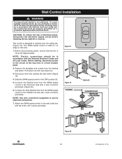
...). Wall Control Installation ! Connect the other BLACK wire from the existing wall switch. Remove the faceplate and screws from the SW46 speed control to the wall outlet box with a wire connector (provided). Before disconnecting power, ensure that the fan is turned off wall switch is rated for 1.2 amps at the main fuse box before installing the fan, light kit or receiver. NOTE: Use wire connectors (supplied) to the circuit at the highest speed. To avoid possible electrical shock, be sure electricity is set at the fuse box...
...). Wall Control Installation ! Connect the other BLACK wire from the existing wall switch. Remove the faceplate and screws from the SW46 speed control to the wall outlet box with a wire connector (provided). Before disconnecting power, ensure that the fan is turned off wall switch is rated for 1.2 amps at the main fuse box before installing the fan, light kit or receiver. NOTE: Use wire connectors (supplied) to the circuit at the highest speed. To avoid possible electrical shock, be sure electricity is set at the fuse box...
Owner Manual
Page 11
... the wall outlet box (Figure 21). 9. Restore power at the main fuse box. 2. Changing or sliding these settings while the fan control is OFF. IMPORTANT Always have the fan switch set at their MAXIMUM SPEED for the blades to stop turning, then slide the reversing switch to HIGH speed before using the wall control. All fans are selected by turning the electricity on its HIGH speed pull chain setting. The fan blades will turn your speed control to the "left" circulate air downward...
... the wall outlet box (Figure 21). 9. Restore power at the main fuse box. 2. Changing or sliding these settings while the fan control is OFF. IMPORTANT Always have the fan switch set at their MAXIMUM SPEED for the blades to stop turning, then slide the reversing switch to HIGH speed before using the wall control. All fans are selected by turning the electricity on its HIGH speed pull chain setting. The fan blades will turn your speed control to the "left" circulate air downward...
Owner Manual
Page 13
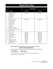
...; MODEL NUMBER The model number of 5) 22 SW46 Wall Control/Plate - Description * Hanger Ball Assembly, Consisting of: 1 Hanger Bracket 2 Hanger Ball 3 Downrod, 4.5" * Parts Bag Containing: 4 Wire Connector (3) 5 Threaded Stud (2) 6 Lockwasher (2) 7 Knurled Knob (2) 8 Pin, Clevis 9 Clip, Hairpin 10 Washer, Paper #10 (21) 11 Screw, #10-32 x 5/16" (21) 12 Flange Screw, 1/4-20 x 1/2" Spare (1) 13 Blade Balance Kit 14 Ceiling Canopy 15 Coupler Cover 16 Upper Glass Retainer 17 Glass Shade 18 Lower Glass Retainer 19 Finial 20 Blade Flange (set of 5) 21 Fan Blade (set of...
...; MODEL NUMBER The model number of 5) 22 SW46 Wall Control/Plate - Description * Hanger Ball Assembly, Consisting of: 1 Hanger Bracket 2 Hanger Ball 3 Downrod, 4.5" * Parts Bag Containing: 4 Wire Connector (3) 5 Threaded Stud (2) 6 Lockwasher (2) 7 Knurled Knob (2) 8 Pin, Clevis 9 Clip, Hairpin 10 Washer, Paper #10 (21) 11 Screw, #10-32 x 5/16" (21) 12 Flange Screw, 1/4-20 x 1/2" Spare (1) 13 Blade Balance Kit 14 Ceiling Canopy 15 Coupler Cover 16 Upper Glass Retainer 17 Glass Shade 18 Lower Glass Retainer 19 Finial 20 Blade Flange (set of 5) 21 Fan Blade (set of...
Owner Manual
Page 14
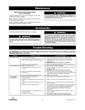
... box. 6. Hanger bracket and/or ceiling outlet box is used and motor noise results choose an alternative control method. 4. Fan blades out of parts or accessories not designated for use only a soft brush or lint free cloth to fan and switch switch wire connections in the switch housing.wire connections in neutral position. 1. Check line wire connections to avoid scratching the finish. Tighten the setscrew in the section on "How to fan before operating. 2. WARNING This product is needed...
... box. 6. Hanger bracket and/or ceiling outlet box is used and motor noise results choose an alternative control method. 4. Fan blades out of parts or accessories not designated for use only a soft brush or lint free cloth to fan and switch switch wire connections in the switch housing.wire connections in neutral position. 1. Check line wire connections to avoid scratching the finish. Tighten the setscrew in the section on "How to fan before operating. 2. WARNING This product is needed...
Owner Manual
Page 15
... EMERSON CEILING FAN EXCEED THE PRICE PAID BY THE ORIGINAL OWNER FOR THE EMERSON CEILING FAN. This limited warranty gives you specific legal rights, and you may not apply to provide all model numbers shown on behalf of Air Comfort Products or Emerson Electric Co. What We Will Do To Correct Problems: If during the one (1) year from its date of original retail purchase. If repair of the motor...
... EMERSON CEILING FAN EXCEED THE PRICE PAID BY THE ORIGINAL OWNER FOR THE EMERSON CEILING FAN. This limited warranty gives you specific legal rights, and you may not apply to provide all model numbers shown on behalf of Air Comfort Products or Emerson Electric Co. What We Will Do To Correct Problems: If during the one (1) year from its date of original retail purchase. If repair of the motor...

Owner Manual
Page 16
F40BP74660000 11/12 Form No. Louis, MO 63136 Questions, problems, missing parts: Before returning to the store call Emerson Electric Customer Service 8 a.m. - 6 p.m., EST, Monday-Friday 1-800-654-3545 www.emersonfans.com Retain this manual for future use. Florissant • St. Part No. BP7466 ETL Model No.: CF110 Air Comfort Products DIVISION OF EMERSON ELECTRIC CO. 8100 W.
F40BP74660000 11/12 Form No. Louis, MO 63136 Questions, problems, missing parts: Before returning to the store call Emerson Electric Customer Service 8 a.m. - 6 p.m., EST, Monday-Friday 1-800-654-3545 www.emersonfans.com Retain this manual for future use. Florissant • St. Part No. BP7466 ETL Model No.: CF110 Air Comfort Products DIVISION OF EMERSON ELECTRIC CO. 8100 W.


