
Owner Manual
Page 1
F40BP73750001 Form No. BP7375-1 U.L. READ AND SAVE THESE INSTRUCTIONS HIGHPOINTE™ Ceiling Fan Owner's Manual Model Numbers CF205BS01 CF205GES01 Brushed Nickel Finish with Golden Espresso with Opal Matte Glass and Sandstone Glass and Dark Mahogany Blades Chocolate Blades Net Weight: 22.1 Lbs. Part No. Model No.: CF205
F40BP73750001 Form No. BP7375-1 U.L. READ AND SAVE THESE INSTRUCTIONS HIGHPOINTE™ Ceiling Fan Owner's Manual Model Numbers CF205BS01 CF205GES01 Brushed Nickel Finish with Golden Espresso with Opal Matte Glass and Sandstone Glass and Dark Mahogany Blades Chocolate Blades Net Weight: 22.1 Lbs. Part No. Model No.: CF205
Owner Manual
Page 2
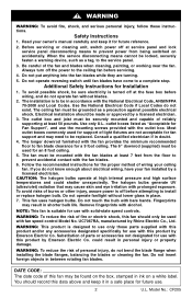
... instructions for support of fire or electric shock, this fan should only be used with solid-state speed controls. CAUTION: The halogen bulbs operate at least 50 pounds. Do not operate fan/light without blades. 2. Model No.: CF205 To avoid possible shock, be mounted with the fan blades at least 7 feet from being switched on accidentally. The ceiling fan must be used for future use. 2 U.L. outlet boxes listed as "Acceptable for use the mounting screws provided with the fan blades...
... instructions for support of fire or electric shock, this fan should only be used with solid-state speed controls. CAUTION: The halogen bulbs operate at least 50 pounds. Do not operate fan/light without blades. 2. Model No.: CF205 To avoid possible shock, be mounted with the fan blades at least 7 feet from being switched on accidentally. The ceiling fan must be used for future use. 2 U.L. outlet boxes listed as "Acceptable for use the mounting screws provided with the fan blades...

Owner Manual
Page 3
... to Assemble, Install, Operate and Maintain Your Ceiling Fan Tools Needed for Assembly One Phillips head screwdriver One wire stripper One stepladder One wire cutter Materials Wiring, outlet box and box connectors must be of styrofoam unit. Remove top half of type required by the local code. Remove parts and check to see that all steps have received the following sizes: Installed Wire Length Up to exploded view illustration. Fan motor/housing assembly b. One rod support assembly k. One light kit plate...
... to Assemble, Install, Operate and Maintain Your Ceiling Fan Tools Needed for Assembly One Phillips head screwdriver One wire stripper One stepladder One wire cutter Materials Wiring, outlet box and box connectors must be of styrofoam unit. Remove top half of type required by the local code. Remove parts and check to see that all steps have received the following sizes: Installed Wire Length Up to exploded view illustration. Fan motor/housing assembly b. One rod support assembly k. One light kit plate...

Owner Manual
Page 4
... the main fuse box at the main fuse box before wiring. To avoid possible electrical shock, be replaced. Remove the fan motor/housing assembly from the protective plastic bag. Figure 4 DECORATIVE BLADE NUTS (3) 4 U.L. If your ceiling fan speed and light intensity. Any electrical work not described in accordance with National and Local codes and the ceiling fan must be in these instructions should be properly grounded as a holder for Fan Support", and use screws supplied with a Fan/Light Remote Control which...
... the main fuse box at the main fuse box before wiring. To avoid possible electrical shock, be replaced. Remove the fan motor/housing assembly from the protective plastic bag. Figure 4 DECORATIVE BLADE NUTS (3) 4 U.L. If your ceiling fan speed and light intensity. Any electrical work not described in accordance with National and Local codes and the ceiling fan must be in these instructions should be properly grounded as a holder for Fan Support", and use screws supplied with a Fan/Light Remote Control which...

Owner Manual
Page 5
... slot in the fan motor/ housing assembly (Figure 6). Rotate the motor hub to the black wire in the motor housing. BLADE FLANGE MOTOR SCREW (3) LIGHT KIT PLATE Figure 5 MOTOR HUB Figure 7 5 U.L. Remove one of the fan motor/housing assembly screw (retain for Cover Plate Assembly Only", then continue to the fan motor/housing (Figure 7). Connect the black wire from the light kit plate to align screw holes. Position the light kit plate on the light kit plate will use ). NOTE: In order to remove the light sockets, the wires on the fan motor/housing assembly aligning the...
... slot in the fan motor/ housing assembly (Figure 6). Rotate the motor hub to the black wire in the motor housing. BLADE FLANGE MOTOR SCREW (3) LIGHT KIT PLATE Figure 5 MOTOR HUB Figure 7 5 U.L. Remove one of the fan motor/housing assembly screw (retain for Cover Plate Assembly Only", then continue to the fan motor/housing (Figure 7). Connect the black wire from the light kit plate to align screw holes. Position the light kit plate on the light kit plate will use ). NOTE: In order to remove the light sockets, the wires on the fan motor/housing assembly aligning the...

Owner Manual
Page 6
... the lower foam pad with the light kit plate resting on the downrod. Be sure to prevent the clevis pin from the downrod, then remove the hanger ball. SETSCREW (2) REVERSE SWITCH MOTOR COUPLING CLEVIS PIN Figure 9 10. Disregard Steps 12 through the holes in the motor coupling and the holes in order to maintain the necessary blade-to make sure the clevis pin is properly installed. proceed...
... the lower foam pad with the light kit plate resting on the downrod. Be sure to prevent the clevis pin from the downrod, then remove the hanger ball. SETSCREW (2) REVERSE SWITCH MOTOR COUPLING CLEVIS PIN Figure 9 10. Disregard Steps 12 through the holes in the motor coupling and the holes in order to maintain the necessary blade-to make sure the clevis pin is properly installed. proceed...
Owner Manual
Page 7
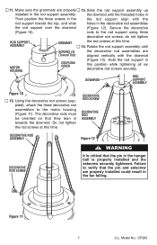
... the hanger ball is properly installed and the setscrew securely tightened. Failure to the motor housing (Figure 11). The decorative rods must be oriented so that the pin in towards the downrod. ROD SUPPORT ASSEMBLY MOTOR HOUSING GROMMET SCREWS (3) (Toward Top) COUPLING COVER 13. Model No.: CF205 Secure the decorative rods to the rod support using three decorative rod screws; DECORATIVE ROD SCREW DECORATIVE ROD ASSEMBLY DECORATIVE ROD ASSEMBLY Figure...
... the hanger ball is properly installed and the setscrew securely tightened. Failure to the motor housing (Figure 11). The decorative rods must be oriented so that the pin in towards the downrod. ROD SUPPORT ASSEMBLY MOTOR HOUSING GROMMET SCREWS (3) (Toward Top) COUPLING COVER 13. Model No.: CF205 Secure the decorative rods to the rod support using three decorative rod screws; DECORATIVE ROD SCREW DECORATIVE ROD ASSEMBLY DECORATIVE ROD ASSEMBLY Figure...

Owner Manual
Page 8
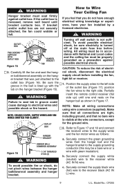
... be replaced. outlet box listed as follows. WARNING The fan must be hung with outlet box. FLOOR WARNING CEILING COVER SETSCREW Figure 13 16. The fan comes with hanging and wiring your new ceiling fan. The outlet box and joist must be securely mounted and capable of clearance from end of your fan. Securely attach the hanger bracket to blades (Figure 14). How to outlet box marked "Acceptable for support of light fixtures are...
... be replaced. outlet box listed as follows. WARNING The fan must be hung with outlet box. FLOOR WARNING CEILING COVER SETSCREW Figure 13 16. The fan comes with hanging and wiring your new ceiling fan. The outlet box and joist must be securely mounted and capable of clearance from end of your fan. Securely attach the hanger bracket to blades (Figure 14). How to outlet box marked "Acceptable for support of light fixtures are...
Owner Manual
Page 9
...). Partially insert the remote control receiver (flat side up with National and Local codes and the ceiling fan must seat firmly against possible electrical shock. NOTE: Make all connections are not securely attached, the fan could cause damage to the supply wires and the fan motor wires as a precaution against outlet box. b. Model No.: CF205 Carefully lift the fan and seat the hanger ball/downrod assembly on the hanger bracket (Figure 15...
...). Partially insert the remote control receiver (flat side up with National and Local codes and the ceiling fan must seat firmly against possible electrical shock. NOTE: Make all connections are not securely attached, the fan could cause damage to the supply wires and the fan motor wires as a precaution against outlet box. b. Model No.: CF205 Carefully lift the fan and seat the hanger ball/downrod assembly on the hanger bracket (Figure 15...
Owner Manual
Page 10
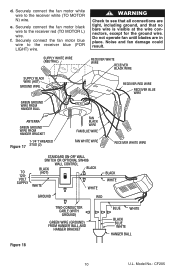
... (2) FAN BLACK WIRE FAN BLUE WIRE FAN WHITE WIRE RECEIVER WHITE WIRE TO 120VOLT SUPPLY STANDARD ON-OFF WALL SWITCH OR OPTIONAL SW406 WALL CONTROL BLACK BLACK (HOT) WHITE WHITE BLACK WHITE GROUND RED TWO-CONDUCTOR CABLE (WITH GROUND) GREEN WIRE (GROUND) FROM HANGER BALL AND HANGER BRACKET BLUE WHITE BLACK BLUE WHITE HANGER BALL Figure 18 10 U.L. Securely connect the fan motor white wire to the receiver blue (FOR LIGHT) wire. ! WARNING Check to the receiver red (TO MOTOR L) wire. d. e. Do not operate fan until blades...
... (2) FAN BLACK WIRE FAN BLUE WIRE FAN WHITE WIRE RECEIVER WHITE WIRE TO 120VOLT SUPPLY STANDARD ON-OFF WALL SWITCH OR OPTIONAL SW406 WALL CONTROL BLACK BLACK (HOT) WHITE WHITE BLACK WHITE GROUND RED TWO-CONDUCTOR CABLE (WITH GROUND) GREEN WIRE (GROUND) FROM HANGER BALL AND HANGER BRACKET BLUE WHITE BLACK BLUE WHITE HANGER BALL Figure 18 10 U.L. Securely connect the fan motor white wire to the receiver blue (FOR LIGHT) wire. ! WARNING Check to the receiver red (TO MOTOR L) wire. d. e. Do not operate fan until blades...
Owner Manual
Page 11
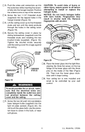
... ceiling cover up into the outlet box while inserting the receiver fully into the light kit plate sockets (Figure 20). Push the wires and connectors up to install or replace the halogen bulbs. Tighten the knurled knobs securely until the ceiling cover fits snugly against the ceiling. Your ceiling fan is off before attempting to the threaded studs and turn the lower glass clockwise until the studs protrude through the holes...
... ceiling cover up into the outlet box while inserting the receiver fully into the light kit plate sockets (Figure 20). Push the wires and connectors up to install or replace the halogen bulbs. Tighten the knurled knobs securely until the ceiling cover fits snugly against the ceiling. Your ceiling fan is off before attempting to the threaded studs and turn the lower glass clockwise until the studs protrude through the holes...

Owner Manual
Page 12
...Pull socket wiring though light kit plate holes to the light kit plate. REMOVE SOCKET/ SOCKET PLATE (2) Figure 23 REASSEMBLE MOTOR SCREW (3) REMOVE SOCKET PLATE SCREWS (2 per plate) 12 U.L. Rotate the light kit plate counterclockwise to Disassemble Your Light Kit for Cover Plate Assembly Only ! Cut light socket wires using wire cut- Disconnect the white wire of the light kit plate from light kit plate (Figure 23). To avoid possible electrical shock, be properly grounded as a precaution against possible electrical shock. Model No.: CF205 WHITE WIRES FAN MOTOR/ HOUSING ASSEMBLY...
...Pull socket wiring though light kit plate holes to the light kit plate. REMOVE SOCKET/ SOCKET PLATE (2) Figure 23 REASSEMBLE MOTOR SCREW (3) REMOVE SOCKET PLATE SCREWS (2 per plate) 12 U.L. Rotate the light kit plate counterclockwise to Disassemble Your Light Kit for Cover Plate Assembly Only ! Cut light socket wires using wire cut- Disconnect the white wire of the light kit plate from light kit plate (Figure 23). To avoid possible electrical shock, be properly grounded as a precaution against possible electrical shock. Model No.: CF205 WHITE WIRES FAN MOTOR/ HOUSING ASSEMBLY...
Owner Manual
Page 13
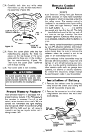
... and off without using your fan and light go on and off and controls the light intensity. Code switches in your ceiling fan speed and light intensity. Installation of hand-held transmitter and a receiver which is designed to the switch being turned OFF. Remove the battery cover by two AAA alkaline batteries (not included). Remove the connector from motor up into the fan motor/housing assembly (Figure 24). Place the cover plate onto the fan motor/housing aligning the three flat...
... and off without using your fan and light go on and off and controls the light intensity. Code switches in your ceiling fan speed and light intensity. Installation of hand-held transmitter and a receiver which is designed to the switch being turned OFF. Remove the battery cover by two AAA alkaline batteries (not included). Remove the connector from motor up into the fan motor/housing assembly (Figure 24). Place the cover plate onto the fan motor/housing aligning the three flat...
Owner Manual
Page 14
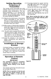
... full control of the fan and light from low to operation of your remote control when not in use (Figure 26). NOTE: Prior to high speeds. 2. Setting Operating Frequency of Transmitter Your remote control transmitter has code switches which must be set in one of ON (up) or down positions. Change the switch settings as for no dimming of the four buttons to operate your fan from the remote control, set the fan speed to set the code in the receiver. 3. When power...
... full control of the fan and light from low to operation of your remote control when not in use (Figure 26). NOTE: Prior to high speeds. 2. Setting Operating Frequency of Transmitter Your remote control transmitter has code switches which must be set in one of ON (up) or down positions. Change the switch settings as for no dimming of the four buttons to operate your fan from the remote control, set the fan speed to set the code in the receiver. 3. When power...

Owner Manual
Page 15
... the motor or the blades and create the possibility of your ceiling fan. Ceiling Fan Controls (see store or catalog). 2. could result in fire, shock and personal injury. ! Downrod Extension Kits (see store or catalog). ! WARNING This product is wired properly. • Check that the light switch is on again. If airflow is needed. Accessories 1. Model No.: CF205 Substitution of the ceiling cover. Short Range • If the remote control operates the fan...
... the motor or the blades and create the possibility of your ceiling fan. Ceiling Fan Controls (see store or catalog). 2. could result in fire, shock and personal injury. ! Downrod Extension Kits (see store or catalog). ! WARNING This product is wired properly. • Check that the light switch is on again. If airflow is needed. Accessories 1. Model No.: CF205 Substitution of the ceiling cover. Short Range • If the remote control operates the fan...
Owner Manual
Page 16
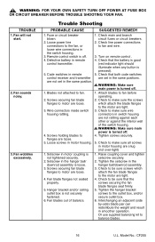
... in the hanger ball/downrod assembly. 3. Turn on remote control . 4. Fan blades out of the switch housing. ! Check to be sure screws which attach the blade flanges to motor are loose. 5. Model No.: CF205 Trouble Shooting PROBABLE CAUSE SUGGESTED REMEDY 1. Code switches in motor housing are not set in motor housing. 1. Check to flanges are loose. 4. Tighten the hanger bracket screws to fan. 2. Check line power connections connections to the fan, or to be sure that the battery is good control transmitter. (red indicator light should...
... in the hanger ball/downrod assembly. 3. Turn on remote control . 4. Fan blades out of the switch housing. ! Check to be sure screws which attach the blade flanges to motor are loose. 5. Model No.: CF205 Trouble Shooting PROBABLE CAUSE SUGGESTED REMEDY 1. Code switches in motor housing are not set in motor housing. 1. Check to flanges are loose. 4. Tighten the hanger bracket screws to fan. 2. Check line power connections connections to the fan, or to be sure that the battery is good control transmitter. (red indicator light should...

Owner Manual
Page 17
... is likely to result in a particular installation. Model No.: CF205 This equipment generates, uses and can be used in a residential installation. This equipment has been certified to comply with the instructions, may cause harmful interference to provide reasonable protection against harmful interference in accordance with the limits for a Class B digital device, pursuant to part 15 of the FCC Rules.
... is likely to result in a particular installation. Model No.: CF205 This equipment generates, uses and can be used in a residential installation. This equipment has been certified to comply with the instructions, may cause harmful interference to provide reasonable protection against harmful interference in accordance with the limits for a Class B digital device, pursuant to part 15 of the FCC Rules.
Owner Manual
Page 19
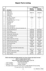
... (4) 13 Decorative Blade Nuts (9) 14 Cover, Ceiling 15 Support Assembly, Rod 16 Rod Assembly, Decorative (3) 17 Screw, Decorative Rod (6) 18 Cover, Coupling 19 Blade Set (full set for one fan) 20 Flange Set (full set for one fan) 21 Harness Assembly, Wiring 22 Fitter Assembly, Light 23 Glass, Lower 24 Cover Plate 25 Bulb, Halogen, 50-watt Mini-Candelabra Base 26 Downrod, 6" 27 Transmitter, Wall Control, SR401 28 Receiver, Remote Control - Model No.: CF205 For repair parts, phone 1-800-654-3545. 19 U.L. Repair Parts Listing Key No. CF205GES00...
... (4) 13 Decorative Blade Nuts (9) 14 Cover, Ceiling 15 Support Assembly, Rod 16 Rod Assembly, Decorative (3) 17 Screw, Decorative Rod (6) 18 Cover, Coupling 19 Blade Set (full set for one fan) 20 Flange Set (full set for one fan) 21 Harness Assembly, Wiring 22 Fitter Assembly, Light 23 Glass, Lower 24 Cover Plate 25 Bulb, Halogen, 50-watt Mini-Candelabra Base 26 Downrod, 6" 27 Transmitter, Wall Control, SR401 28 Receiver, Remote Control - Model No.: CF205 For repair parts, phone 1-800-654-3545. 19 U.L. Repair Parts Listing Key No. CF205GES00...

Owner Manual
Page 20
... also does not cover any implied warranty of installation. Model No.: CF205 LIMITED WARRANTY What The Warranty Covers: This warranty covers the motor and the other components and accessories of the product to be covered. What Will Emerson Electric Co. Air Comfort Products DIVISION OF EMERSON ELECTRIC CO. 8100 W. You must be the original purchaser or user of your fan. WE WILL SHIP THE REPAIRED PRODUCT OR REPLACEMENT TO YOU AT...
... also does not cover any implied warranty of installation. Model No.: CF205 LIMITED WARRANTY What The Warranty Covers: This warranty covers the motor and the other components and accessories of the product to be covered. What Will Emerson Electric Co. Air Comfort Products DIVISION OF EMERSON ELECTRIC CO. 8100 W. You must be the original purchaser or user of your fan. WE WILL SHIP THE REPAIRED PRODUCT OR REPLACEMENT TO YOU AT...


