

Owner Manual
Page 1
... SAVE THESE INSTRUCTIONS CURVA™ 44" & 52" Damp & Wet Location Snugger Ceiling Fan Owner's Manual 44" Model Numbers for Damp Locations CF244BS00 Brushed Steel CF244CRM00 Chrome 52" Model Numbers for Damp Locations CF252BS00 Brushed Steel CF252CRM00 Chrome 44" Model Numbers for Wet Locations CF244WW00 Appliance White CF244ORB00 Oil Rubbed Bronze 52" Model Numbers for Wet Locations CF252WW00 Appliance White CF252ORB00 Oil Rubbed Bronze Net Weight: 18.3 Lbs. Net Weight: 19.2 Lbs. BP7408-3 U.L. Questions, problems, missing parts: Before...
... SAVE THESE INSTRUCTIONS CURVA™ 44" & 52" Damp & Wet Location Snugger Ceiling Fan Owner's Manual 44" Model Numbers for Damp Locations CF244BS00 Brushed Steel CF244CRM00 Chrome 52" Model Numbers for Damp Locations CF252BS00 Brushed Steel CF252CRM00 Chrome 44" Model Numbers for Wet Locations CF244WW00 Appliance White CF244ORB00 Oil Rubbed Bronze 52" Model Numbers for Wet Locations CF252WW00 Appliance White CF252ORB00 Oil Rubbed Bronze Net Weight: 18.3 Lbs. Net Weight: 19.2 Lbs. BP7408-3 U.L. Questions, problems, missing parts: Before...

Owner Manual
Page 2
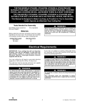
... use with the fan blades. 6. Additional Safety Instructions for the proper method of fire or electric shock, this fan may need to prevent power from the floor to fan blade clearance for use the mounting screws provided with the outlet box. All wiring must be in ink on accidentally. The ceiling fan must be found on the box, stamped in accordance with fan speed control Model No. Most outlet boxes commonly used with the National Electrical Code...
... use with the fan blades. 6. Additional Safety Instructions for the proper method of fire or electric shock, this fan may need to prevent power from the floor to fan blade clearance for use the mounting screws provided with the outlet box. All wiring must be in ink on accidentally. The ceiling fan must be found on the box, stamped in accordance with fan speed control Model No. Most outlet boxes commonly used with the National Electrical Code...

Owner Manual
Page 3
... 3 10 1 1 1 2 2 2 1 PACKAGE CONTENTS Part Description A Fan Motor Assembly B Ceiling Cover C Coupler Cover D Fan Blades E Lower Housing F Light Kit Plate G Glass Shade H No-Light Cover Plate I Hanger Bracket J Hanger Ball/Downrod Assembly K 6-Speed Electronic Receiver Control with Parts Bag L 6-Speed Handheld Transmitter with Wall Bracket M 50-Watt Halogen Mini Candelabra Bulbs Quantity 1 1 1 3 1 1 1 1 1 1 1 1 2 F G A H B I J C K E M L D 1 2 4 5 7 8 2. Substitution of parts or accessories not designated for use with this product by Emerson Electric Co. WARNING This...
... 3 10 1 1 1 2 2 2 1 PACKAGE CONTENTS Part Description A Fan Motor Assembly B Ceiling Cover C Coupler Cover D Fan Blades E Lower Housing F Light Kit Plate G Glass Shade H No-Light Cover Plate I Hanger Bracket J Hanger Ball/Downrod Assembly K 6-Speed Electronic Receiver Control with Parts Bag L 6-Speed Handheld Transmitter with Wall Bracket M 50-Watt Halogen Mini Candelabra Bulbs Quantity 1 1 1 3 1 1 1 1 1 1 1 1 2 F G A H B I J C K E M L D 1 2 4 5 7 8 2. Substitution of parts or accessories not designated for use with this product by Emerson Electric Co. WARNING This...
Owner Manual
Page 4
... outlet boxes commonly used for support of light fixtures are not acceptable for Fan Support of type required by a licensed electrician. If your fan (page 8). The minimum wire would be a 3-conductor (2-wire with ground) of following size: Installed Wire Length Up to outlet box marked "Acceptable for fan support and may be damaged, if used with any wall dimmer switch or control other than the Emerson Electric Fan/Light Remote Control supplied with National and Local codes and the ceiling fan...
... outlet boxes commonly used for support of light fixtures are not acceptable for Fan Support of type required by a licensed electrician. If your fan (page 8). The minimum wire would be a 3-conductor (2-wire with ground) of following size: Installed Wire Length Up to outlet box marked "Acceptable for fan support and may be damaged, if used with any wall dimmer switch or control other than the Emerson Electric Fan/Light Remote Control supplied with National and Local codes and the ceiling fan...

Owner Manual
Page 5
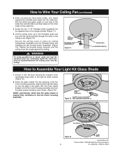
... fan housing assembly when installing blades. 3. Connect the blue wire from the ceiling fan to make connections. 8. Use wire connectors (previously removed) to the black wire of the light kit plate. Remove one of the three screws in fan housing assembly. Secure the light kit plate assembly by placing the cut out notches over the fan housing dimples (Figure 4). Ceiling Fan Assembly General Your Emerson ceiling fan comes supplied with a Fan/Light Remote Control which consists of a receiver mounted inside the ceiling cover of the light kit plate (Figure 3). Position the fan motor...
... fan housing assembly when installing blades. 3. Connect the blue wire from the ceiling fan to make connections. 8. Use wire connectors (previously removed) to the black wire of the light kit plate. Remove one of the three screws in fan housing assembly. Secure the light kit plate assembly by placing the cut out notches over the fan housing dimples (Figure 4). Ceiling Fan Assembly General Your Emerson ceiling fan comes supplied with a Fan/Light Remote Control which consists of a receiver mounted inside the ceiling cover of the light kit plate (Figure 3). Position the fan motor...

Owner Manual
Page 6
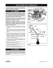
... (2) CEILING COVER SETSCREW Figure 8 6 U.L. Retain the pin and hanger ball for final assembly. 12. Route the motor lead wires through the downrod. Route the motor leads through the downrod. Model No.: CF244 & CF252 Loosen setscrew in the top of the hairpin clip through the two holes in the downrod and align the ball so the pin is properly installed. ! Be sure to 9-inches above , or fan...
... (2) CEILING COVER SETSCREW Figure 8 6 U.L. Retain the pin and hanger ball for final assembly. 12. Route the motor lead wires through the downrod. Route the motor leads through the downrod. Model No.: CF244 & CF252 Loosen setscrew in the top of the hairpin clip through the two holes in the downrod and align the ball so the pin is properly installed. ! Be sure to 9-inches above , or fan...

Owner Manual
Page 7
... electrical power to the branch circuit at the main fuse box before attempting to the outlet box (Figure 11). Securely attach the hanger bracket to the outlet box using the two screws supplied with the tab on the hanger bracket that was just attached to install the ceiling fan mounting plate on the outlet box. ! WARNING To avoid possible fire or shock, do not pinch wires between the hanger ball/downrod assembly...
... electrical power to the branch circuit at the main fuse box before attempting to the outlet box (Figure 11). Securely attach the hanger bracket to the outlet box using the two screws supplied with the tab on the hanger bracket that was just attached to install the ceiling fan mounting plate on the outlet box. ! WARNING To avoid possible fire or shock, do not pinch wires between the hanger ball/downrod assembly...
Owner Manual
Page 8
... fuse box before installing the fan, light kit or receiver. WARNING Check to the grounding conductor of supply (this may be sure electricity is turned off wall switch is not sufficient. Do not operate fan until blades are tight, including ground, and that no bare wire is visible at the wire connectors, except for the ground wire. Model No.: CF244 & CF252 Refer to Figures 12 and 13 to connect the receiver wires...
... fuse box before installing the fan, light kit or receiver. WARNING Check to the grounding conductor of supply (this may be sure electricity is turned off wall switch is not sufficient. Do not operate fan until blades are tight, including ground, and that no bare wire is visible at the wire connectors, except for the ground wire. Model No.: CF244 & CF252 Refer to Figures 12 and 13 to connect the receiver wires...
Owner Manual
Page 9
... MINI CANDELABRA BASE BULBS (2) FLAT AREA (3) DIMPLES (3) Figure 16 GLASS BOWL emersonfans.com Please contact 1-800-654-3545 for further assistance 9 U.L. Secure the ceiling cover in the light kit plate sockets (Figure 15). 2. Model No.: CF244 & CF252 Tighten the knurled knobs securely until it stops (Figure 16). Screw the two 1-1/4" threaded studs (supplied) into the tapped holes in the fan motor housing assembly, aligning the three...
... MINI CANDELABRA BASE BULBS (2) FLAT AREA (3) DIMPLES (3) Figure 16 GLASS BOWL emersonfans.com Please contact 1-800-654-3545 for further assistance 9 U.L. Secure the ceiling cover in the light kit plate sockets (Figure 15). 2. Model No.: CF244 & CF252 Tighten the knurled knobs securely until it stops (Figure 16). Screw the two 1-1/4" threaded studs (supplied) into the tapped holes in the fan motor housing assembly, aligning the three...
Owner Manual
Page 10
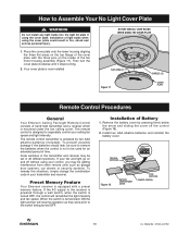
... the light and fan will remember the light intensity and fan speed. Installation of the cover plate with a preset memory feature. Code switches in the transmitter and receiver may be used for an extended period of the fan motor housing assembly (Figure 17). When the switch is mounted under the fan ceiling cover. Model No.: CF244 & CF252 Place the cover plate onto the lower housing aligning the three flat areas on the top flange of light bulbs when using the cover plate. The remote control transmitter...
... the light and fan will remember the light intensity and fan speed. Installation of the cover plate with a preset memory feature. Code switches in the transmitter and receiver may be used for an extended period of the fan motor housing assembly (Figure 17). When the switch is mounted under the fan ceiling cover. Model No.: CF244 & CF252 Place the cover plate onto the lower housing aligning the three flat areas on the top flange of light bulbs when using the cover plate. The remote control transmitter...
Owner Manual
Page 11
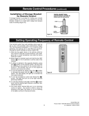
... INSTALL BRACKET TO WALL: SLIDE THE COVER UP TO EXPOSE THE SCREW HOLES FOR INSTALLATION COVER WALL BRACKET Figure 19 SCREW HOLES (2) Setting Operating Frequency of Remote Control Your remote control has code switches which must be set in the opposite direction, press the ( ) button on at any speed for the reverse button to allow for dimming of the lights. To turn in the receiver. 3. Set switch to I is away from excess heat or humidity (Figure 19). Model No.: CF244...
... INSTALL BRACKET TO WALL: SLIDE THE COVER UP TO EXPOSE THE SCREW HOLES FOR INSTALLATION COVER WALL BRACKET Figure 19 SCREW HOLES (2) Setting Operating Frequency of Remote Control Your remote control has code switches which must be set in the opposite direction, press the ( ) button on at any speed for the reverse button to allow for dimming of the lights. To turn in the receiver. 3. Set switch to I is away from excess heat or humidity (Figure 19). Model No.: CF244...

Owner Manual
Page 12
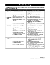
... U.L. WARNING The use screws supplied with Federal Law, this ceiling fan is needed. Remote Control Trouble Shooting Fan/Light Fails to finish. ! Downrod Extension Kits (see store or catalog). ! WARNING To reduce the risk of fire, electric shock, or personal injury, mount fan to outlet box marked "Acceptable for fan support and may need to be avoided to prevent damage to Operate • Check that the speed switch on the fan is set in fire, shock...
... U.L. WARNING The use screws supplied with Federal Law, this ceiling fan is needed. Remote Control Trouble Shooting Fan/Light Fails to finish. ! Downrod Extension Kits (see store or catalog). ! WARNING To reduce the risk of fire, electric shock, or personal injury, mount fan to outlet box marked "Acceptable for fan support and may need to be avoided to prevent damage to Operate • Check that the speed switch on the fan is set in fire, shock...
Owner Manual
Page 13
... motor are tight. ! Fan wobbles excessively. 1. Screws securing fan blades to balance blades. 1. Turn ON Fan/Light Remote Control. 1. Or use supplied balancing kit to motor are very hot and can redistribute the weight and result in the hanger ball/downrod assembly is turned off before operating. 2. WARNING: FOR YOUR OWN SAFETY TURN OFF POWER AT FUSE BOX OR CIRCUIT BREAKER BEFORE TROUBLE SHOOTING YOUR FAN. Lamps turn on and then turn off and replace...
... motor are tight. ! Fan wobbles excessively. 1. Screws securing fan blades to balance blades. 1. Turn ON Fan/Light Remote Control. 1. Or use supplied balancing kit to motor are very hot and can redistribute the weight and result in the hanger ball/downrod assembly is turned off before operating. 2. WARNING: FOR YOUR OWN SAFETY TURN OFF POWER AT FUSE BOX OR CIRCUIT BREAKER BEFORE TROUBLE SHOOTING YOUR FAN. Lamps turn on and then turn off and replace...
Owner Manual
Page 15
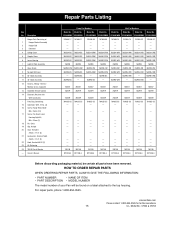
...: • PART NUMBER • NAME OF ITEM • PART DESCRIPTION • MODEL NUMBER The model number of : 1 Hanger Bracket Assembly 2 Hanger Ball 3 Downrod 4 Ceiling Cover 5 Coupler Cover 6 Lower Housing 7 Light Kit Plate Assembly 8 Glass Shade 9 No Light Kit Cover 10 52" Blade Assembly 11 44" Blade Assembly 12 Harness, Wiring - emersonfans.com Please contact 1-800-654-3545 for further assistance 15 U.L. Model No.: CF244 & CF252 Model No. Owner's Manual Damp Part Numbers Wet Part Numbers Model No. Model No. For repair parts, phone 1-800-654-3545. Model No...
...: • PART NUMBER • NAME OF ITEM • PART DESCRIPTION • MODEL NUMBER The model number of : 1 Hanger Bracket Assembly 2 Hanger Ball 3 Downrod 4 Ceiling Cover 5 Coupler Cover 6 Lower Housing 7 Light Kit Plate Assembly 8 Glass Shade 9 No Light Kit Cover 10 52" Blade Assembly 11 44" Blade Assembly 12 Harness, Wiring - emersonfans.com Please contact 1-800-654-3545 for further assistance 15 U.L. Model No.: CF244 & CF252 Model No. Owner's Manual Damp Part Numbers Wet Part Numbers Model No. Model No. For repair parts, phone 1-800-654-3545. Model No...
Owner Manual
Page 16
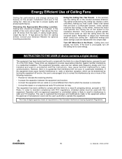
..., pursuant to part 15 of the room and at low speed in the middle of the FCC Rules. Model No.: CF244 & CF252 Select a fan speed that changes and modifications made to the equipment without the approval of the Canadian Interference-Causing Equipment Regulations. 16 U.L. In the winter, reverse the motor and operate the ceiling fan at least 7 feet above the floor for optional mounting accessories. additional...
..., pursuant to part 15 of the room and at low speed in the middle of the FCC Rules. Model No.: CF244 & CF252 Select a fan speed that changes and modifications made to the equipment without the approval of the Canadian Interference-Causing Equipment Regulations. 16 U.L. In the winter, reverse the motor and operate the ceiling fan at least 7 feet above the floor for optional mounting accessories. additional...
Owner Manual
Page 19
... to the Emerson Ceiling Fan package you ship to the address listed at our factory or authorized service center, use of parts or accessories not provided to you at 1-800-237-6511 to and expressly excludes: • The glass globes and light bulbs of this limited warranty. Once we will ship the repaired or the replacement Emerson Ceiling Fan to you as part of your Owner's Manual. What Is Not Covered: This limited warranty does...
... to the Emerson Ceiling Fan package you ship to the address listed at our factory or authorized service center, use of parts or accessories not provided to you at 1-800-237-6511 to and expressly excludes: • The glass globes and light bulbs of this limited warranty. Once we will ship the repaired or the replacement Emerson Ceiling Fan to you as part of your Owner's Manual. What Is Not Covered: This limited warranty does...

Owner Manual
Page 20
F40BP74080003 Revision: 130211 Printed in China 02/13 Form No. Air Comfort Products DIVISION OF EMERSON ELECTRIC CO. 8100 W. Louis, MO 63136 Questions, problems, missing parts: Before returning to the store call Emerson Electric Customer Service 8 a.m. - 6 p.m., EST, Monday-Friday 1-800-654-3545 www.emersonfans.com Retain this manual for future use. Model No.: CF244 & CF252 Part No. BP7408-3 U.L. Florissant • St.
F40BP74080003 Revision: 130211 Printed in China 02/13 Form No. Air Comfort Products DIVISION OF EMERSON ELECTRIC CO. 8100 W. Louis, MO 63136 Questions, problems, missing parts: Before returning to the store call Emerson Electric Customer Service 8 a.m. - 6 p.m., EST, Monday-Friday 1-800-654-3545 www.emersonfans.com Retain this manual for future use. Model No.: CF244 & CF252 Part No. BP7408-3 U.L. Florissant • St.


