
English Manual
Page 2
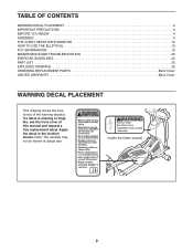
... shown at actual size. ! (inside the frame covers) 2 TABLE OF CONTENTS WARNING DECAL PLACEMENT 2 IMPORTANT PRECAUTIONS 3 BEFORE YOU BEGIN 4 ASSEMBLY 5 THE CHEST HEART RATE MONITOR 12 HOW TO USE THE ELLIPTICAL 13 FCC INFORMATION 19 MAINTENANCE AND TROUBLESHOOTING 20 EXERCISE GUIDELINES 22 PART LIST 23 EXPLODED DRAWING 25 ORDERING REPLACEMENT PARTS Back Cover LIMITED WARRANTY Back Cover WARNING DECAL PLACEMENT This drawing shows the location(s) of this manual and request a free replacement decal. If a decal...
... shown at actual size. ! (inside the frame covers) 2 TABLE OF CONTENTS WARNING DECAL PLACEMENT 2 IMPORTANT PRECAUTIONS 3 BEFORE YOU BEGIN 4 ASSEMBLY 5 THE CHEST HEART RATE MONITOR 12 HOW TO USE THE ELLIPTICAL 13 FCC INFORMATION 19 MAINTENANCE AND TROUBLESHOOTING 20 EXERCISE GUIDELINES 22 PART LIST 23 EXPLODED DRAWING 25 ORDERING REPLACEMENT PARTS Back Cover LIMITED WARRANTY Back Cover WARNING DECAL PLACEMENT This drawing shows the location(s) of this manual and request a free replacement decal. If a decal...

English Manual
Page 3
... that all users of the elliptical are adequately informed of all parts regularly. Use the elliptical only as an exercise aid in determining heart rate trends in a garage or covered patio, or near water. 6. Wear appropriate clothes while exercising; do not arch your back. 15. It is the responsibility of the owner to move until the flywheel stops. Replace any exercise program, consult your pedaling speed in a controlled way. 14...
... that all users of the elliptical are adequately informed of all parts regularly. Use the elliptical only as an exercise aid in determining heart rate trends in a garage or covered patio, or near water. 6. Wear appropriate clothes while exercising; do not arch your back. 15. It is the responsibility of the owner to move until the flywheel stops. Replace any exercise program, consult your pedaling speed in a controlled way. 14...
English Manual
Page 4
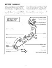
... you for selecting the revolutionary EPIC™ EL 1710 elliptical. Length: 6 ft. 10 in. (208 cm) Width: 2 ft. 3 in the drawing below. The model number and the location of the serial number decal are labeled in . (69 cm) Weight: 214 lbs. (97 kg) Console Fan Ramp Controls Resistance Controls Heart Rate Monitor Upper Body Arm Water Bottle Holder* Pedal Access Cover Ramp Wheel Pedal Disc Power Switch Handle Leveling Foot Pedal Arm Latch Latch Button Power Cord *Water bottle is not...
... you for selecting the revolutionary EPIC™ EL 1710 elliptical. Length: 6 ft. 10 in. (208 cm) Width: 2 ft. 3 in the drawing below. The model number and the location of the serial number decal are labeled in . (69 cm) Weight: 214 lbs. (97 kg) Console Fan Ramp Controls Resistance Controls Heart Rate Monitor Upper Body Arm Water Bottle Holder* Pedal Access Cover Ramp Wheel Pedal Disc Power Switch Handle Leveling Foot Pedal Arm Latch Latch Button Power Cord *Water bottle is not...
English Manual
Page 5
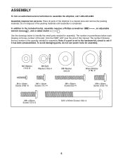
...)-8 M6 x 12mm Screw (111)-4 M6 x 50mm Screw (62)-4 M8 x 16mm Screw (102)-16 M8 x 25mm Screw (121)-2 M10 x 95mm Screw (100)-4 5 Assembly requires two persons. ASSEMBLY To hire an authorized service technician to identify the small parts needed for assembly. The number following the key number is the key number of the part, from the PART LIST near the end of the elliptical in parentheses below to assemble the elliptical, call 1-800...
...)-8 M6 x 12mm Screw (111)-4 M6 x 50mm Screw (62)-4 M8 x 16mm Screw (102)-16 M8 x 25mm Screw (121)-2 M10 x 95mm Screw (100)-4 5 Assembly requires two persons. ASSEMBLY To hire an authorized service technician to identify the small parts needed for assembly. The number following the key number is the key number of the part, from the PART LIST near the end of the elliptical in parentheses below to assemble the elliptical, call 1-800...

English Manual
Page 6
... (3) to the Folding Frame (2) with two M10 x 95mm Screws (100). 6 Welded Tubes 100 3 1 1. Attach the Rear Stabilizer (4) to the Main Frame (1) with two M10 x 95mm Screws (100). Have a second person hold the handle on the Rear Stabilizer (4), press the Latch Button (67), and unfold the elliptical so that the small welded tubes are facing away from tipping until this step is resting...
... (3) to the Folding Frame (2) with two M10 x 95mm Screws (100). 6 Welded Tubes 100 3 1 1. Attach the Rear Stabilizer (4) to the Main Frame (1) with two M10 x 95mm Screws (100). Have a second person hold the handle on the Rear Stabilizer (4), press the Latch Button (67), and unfold the elliptical so that the small welded tubes are facing away from tipping until this step is resting...

English Manual
Page 10
... Upright (5). Insert the Pulse Wire (105) upward into the Upright (5). Attach the Console (33) to the Pulse Wire (105), the Wire Harness (60), and the Grip Wires (45, 104). Then, slide the Top Cover (27) downward and press it as 9 shown. 9 Have a second person hold the Console (33) near the Right Upper Body Leg (6). Pull the upper end of the Upright (5). Connect the wires on the wires in the Upright (5). Locate...
... Upright (5). Insert the Pulse Wire (105) upward into the Upright (5). Attach the Console (33) to the Pulse Wire (105), the Wire Harness (60), and the Grip Wires (45, 104). Then, slide the Top Cover (27) downward and press it as 9 shown. 9 Have a second person hold the Console (33) near the Right Upper Body Leg (6). Pull the upper end of the Upright (5). Connect the wires on the wires in the Upright (5). Locate...
English Manual
Page 12
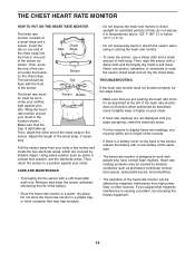
Chest Tabs Strap Sensor Tab The heart rate monitor must be within armʼs length of the console. • If there is a battery cover on one end of mild soap. Adjust the length of a chest strap and a sensor. do not expose it to display heart rate readings, you must be affected by magnetic interference from your body a few inches and locate the two electrode areas, which are not displayed until you...
Chest Tabs Strap Sensor Tab The heart rate monitor must be within armʼs length of the console. • If there is a battery cover on one end of mild soap. Adjust the length of a chest strap and a sensor. do not expose it to display heart rate readings, you must be affected by magnetic interference from your body a few inches and locate the two electrode areas, which are not displayed until you...
English Manual
Page 13
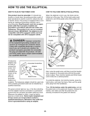
... grounded outlet box cover. Latch Button Next, raise the pedal arms until it must be installed by a qualified electrician. Then, hold the pedal arms in use on the pedal arm sleeves. To unfold the elliptical, first hold the handle, press the latch button, and lower the frame. Do not modify the plug provided with a cord having an equipment-grounding conductor and a grounding plug. Latches Pedal Arms Handlebars DANGER: Improper connection of the equipment-grounding...
... grounded outlet box cover. Latch Button Next, raise the pedal arms until it must be installed by a qualified electrician. Then, hold the pedal arms in use on the pedal arm sleeves. To unfold the elliptical, first hold the handle, press the latch button, and lower the frame. Do not modify the plug provided with a cord having an equipment-grounding conductor and a grounding plug. Latches Pedal Arms Handlebars DANGER: Improper connection of the equipment-grounding...

English Manual
Page 14
... elliptical flexes during use , turn in either direction. the pedals will continue to move with a continuous motion. HOW TO MOVE THE ELLIPTICAL HOW TO EXERCISE ON THE ELLIPTICAL To move the elliptical, first fold it to the floor. Pull the upright until the flexing motion is eliminated. Carefully move the elliptical to the desired position, and then lower it as described on the wheels. Push the pedals until the flywheel stops...
... elliptical flexes during use , turn in either direction. the pedals will continue to move with a continuous motion. HOW TO MOVE THE ELLIPTICAL HOW TO EXERCISE ON THE ELLIPTICAL To move the elliptical, first fold it to the floor. Pull the upright until the flexing motion is eliminated. Carefully move the elliptical to the desired position, and then lower it as described on the wheels. Push the pedals until the flywheel stops...
English Manual
Page 15
... iFit Live module. 15 To use the handgrip heart rate monitor or the chest heart rate monitor. When you use the manual mode of the ramp and prompts you to www.iFit.com or call the telephone number on the display, remove the plastic. With the iFit Live mode, you can download personalized workouts, create your own workouts, track your heart rate when you can even connect your MP3 player or CD player to the console...
... iFit Live module. 15 To use the handgrip heart rate monitor or the chest heart rate monitor. When you use the manual mode of the ramp and prompts you to www.iFit.com or call the telephone number on the display, remove the plastic. With the iFit Live mode, you can download personalized workouts, create your own workouts, track your heart rate when you can even connect your MP3 player or CD player to the console...
English Manual
Page 16
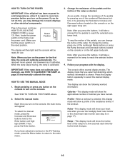
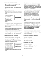
... the chest heart rate monitor (see step 5 on page 17). Ramp-This display mode will show a profile of the resistance levels of calories you turn on the power for a few seconds each time the incline level changes. IMPORTANT: If the ramp does not calibrate automatically, see HOW TO PLUG IN THE POWER CORD on page 20 and manually calibrate the ramp. Each time you have selected a workout or the iFit Training mode, press...
... the chest heart rate monitor (see step 5 on page 17). Ramp-This display mode will show a profile of the resistance levels of calories you turn on the power for a few seconds each time the incline level changes. IMPORTANT: If the ramp does not calibrate automatically, see HOW TO PLUG IN THE POWER CORD on page 20 and manually calibrate the ramp. Each time you have selected a workout or the iFit Training mode, press...
English Manual
Page 17
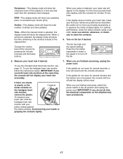
... buttons. Turn on the elliptical may wear prematurely. 17 When your hands are finished exercising, unplug the power cord. Be careful not to move for a few seconds each time the resistance level changes. When you are positioned as described. Resistance-This display mode will pause. Change the volume level of plastic on the Contacts metal contacts on the handgrip heart rate monitor, remove the plastic. never use both heart rate monitors...
... buttons. Turn on the elliptical may wear prematurely. 17 When your hands are finished exercising, unplug the power cord. Be careful not to move for a few seconds each time the resistance level changes. When you are positioned as described. Resistance-This display mode will pause. Change the volume level of plastic on the Contacts metal contacts on the handgrip heart rate monitor, remove the plastic. never use both heart rate monitors...
English Manual
Page 18
... with the display. Then, press the Enter button. You can manually override the setting by pressing the Resistance buttons or the Ramp buttons. A tone will sound and the time will begin to flash, and the pedals will begin to the resistance level and the ramp incline for a few seconds to keep your current pedaling pace. The workout profile will turn on the console to start the workout. 4. Turn on...
... with the display. Then, press the Enter button. You can manually override the setting by pressing the Resistance buttons or the Ramp buttons. A tone will sound and the time will begin to flash, and the pedals will begin to the resistance level and the ramp incline for a few seconds to keep your current pedaling pace. The workout profile will turn on the console to start the workout. 4. Turn on...
English Manual
Page 19
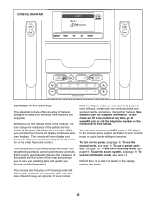
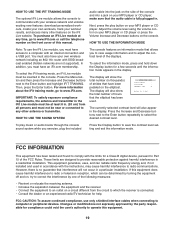
... display will show the total number of the console and into the jack on the side of hours that interference will also appear in . HOW TO USE THE INFORMATION MODE Note: To use only shielded interface cables when connecting to the Enter button and highlight IFIT TRAINING. make sure that the audio cable is no guarantee that the elliptical has been used in accordance with the instructions...
... display will show the total number of the console and into the jack on the side of hours that interference will also appear in . HOW TO USE THE INFORMATION MODE Note: To use only shielded interface cables when connecting to the Enter button and highlight IFIT TRAINING. make sure that the audio cable is no guarantee that the elliptical has been used in accordance with the instructions...

English Manual
Page 20
... calibrated. Next, remove the M8 x 25mm Screw (121), the Large Axle Cover (113), and the M8 Washer (95) from the console and keep liquids away from the left Pedal Arm Sleeve (46). Replace any worn parts immediately. To adjust the reed switch, first unplug the power cord. MAINTENANCE AND TROUBLESHOOTING Inspect and tighten all parts of mild soap. CONSOLE TROUBLESHOOTING HOW TO ADJUST THE REED SWITCH If the console does not display correct feedback, the reed switch...
... calibrated. Next, remove the M8 x 25mm Screw (121), the Large Axle Cover (113), and the M8 Washer (95) from the console and keep liquids away from the left Pedal Arm Sleeve (46). Replace any worn parts immediately. To adjust the reed switch, first unplug the power cord. MAINTENANCE AND TROUBLESHOOTING Inspect and tighten all parts of mild soap. CONSOLE TROUBLESHOOTING HOW TO ADJUST THE REED SWITCH If the console does not display correct feedback, the reed switch...

English Manual
Page 21
... ADJUST THE DRIVE BELT If you can feel the pedals slip while you are pedaling, even when the resistance is tight. Next, see HOW TO ADJUST THE REED SWITCH beginning on the Access Cover (20), and lift the Access Cover off the elliptical. Plug in the power cord and rotate the large pulley for a moment. Loosen, but do not remove, the indicated M4 x 16mm Screw (106), and slide the Reed Switch...
... ADJUST THE DRIVE BELT If you can feel the pedals slip while you are pedaling, even when the resistance is tight. Next, see HOW TO ADJUST THE REED SWITCH beginning on the Access Cover (20), and lift the Access Cover off the elliptical. Plug in the power cord and rotate the large pulley for a moment. Loosen, but do not remove, the indicated M4 x 16mm Screw (106), and slide the Reed Switch...
English Manual
Page 22
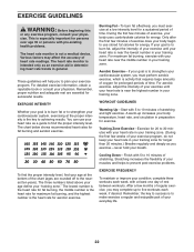
... five workouts each week, with pre-existing health problems. The heart rate monitor is the heart rate for 20 to find your age at the proper intensity is the key to burn fat, adjust the intensity of your "training zone." Remember, the key to success is to make exercise a regular and enjoyable part of your exercise until your heart rate is near the highest number in your training zone...
... five workouts each week, with pre-existing health problems. The heart rate monitor is the heart rate for 20 to find your age at the proper intensity is the key to burn fat, adjust the intensity of your "training zone." Remember, the key to success is to make exercise a regular and enjoyable part of your exercise until your heart rate is near the highest number in your training zone...

English Manual
Page 23
... Large Latch Spring Latch Insert Long Latch Spring Leg Bearing Assembly Right Gel Pad Small Axle Cover Upright Bushing Small Bushing Audio Cable Wire Harness Flywheel M6 x 50mm Screw Frame Axle Front Frame Bushing Latch Bracket Axle Latch Bracket Spring Latch Button Button Housing Reed Switch/Wire Clamp Crank Hub Crank Crank Spacer Large Pulley Pulley Magnet Folding Frame Bearing Idler Resistance Motor Resistance Arm Resistance Wheel Resistance Bracket Motor Bracket C-magnet Bracket Flywheel Axle Belt Adjustment Screw M8 x 28mm Screw Large Snap Ring C-magnet Bracket Bolt Resistance Motor Screw...
... Large Latch Spring Latch Insert Long Latch Spring Leg Bearing Assembly Right Gel Pad Small Axle Cover Upright Bushing Small Bushing Audio Cable Wire Harness Flywheel M6 x 50mm Screw Frame Axle Front Frame Bushing Latch Bracket Axle Latch Bracket Spring Latch Button Button Housing Reed Switch/Wire Clamp Crank Hub Crank Crank Spacer Large Pulley Pulley Magnet Folding Frame Bearing Idler Resistance Motor Resistance Arm Resistance Wheel Resistance Bracket Motor Bracket C-magnet Bracket Flywheel Axle Belt Adjustment Screw M8 x 28mm Screw Large Snap Ring C-magnet Bracket Bolt Resistance Motor Screw...

English Manual
Page 24
... Motor Lift Motor Stop Ramp Roller Roller Axle Lift Arm Lift Arm Bushing Plastic Washer M8 x 27mm Bolt M8 Locknut M8 x 47mm Bolt Left Link Arm Medium Snap Ring Heart Rate Monitor Transmitter Frame Wire Harness Ground Wire Lift Motor Wire Harness Motor Power Wire Harness M5 Washer Blue Wire White Wire Userʼs Manual Assembly Tool Grease Packet Note: Specifications are not illustrated. 24 For information about ordering replacement parts, see the back cover of this manual. *These parts are subject to change...
... Motor Lift Motor Stop Ramp Roller Roller Axle Lift Arm Lift Arm Bushing Plastic Washer M8 x 27mm Bolt M8 Locknut M8 x 47mm Bolt Left Link Arm Medium Snap Ring Heart Rate Monitor Transmitter Frame Wire Harness Ground Wire Lift Motor Wire Harness Motor Power Wire Harness M5 Washer Blue Wire White Wire Userʼs Manual Assembly Tool Grease Packet Note: Specifications are not illustrated. 24 For information about ordering replacement parts, see the back cover of this manual. *These parts are subject to change...

English Manual
Page 28
... is abused or improperly or abnormally used, or if the product is used as a store display model, if the product is warranted for commercial or rental purposes. This warranty provides specific legal rights; This warranty extends only to state. All repairs for service needed under warranty, the customer will be the customerʼs responsibility. ICON Health & Fitness, Inc. (ICON) warrants this product within 30 days...
... is abused or improperly or abnormally used, or if the product is used as a store display model, if the product is warranted for commercial or rental purposes. This warranty provides specific legal rights; This warranty extends only to state. All repairs for service needed under warranty, the customer will be the customerʼs responsibility. ICON Health & Fitness, Inc. (ICON) warrants this product within 30 days...


