User Manual
Page 2
... not apply to fuses, disposable batteries, or to any other provision. Fluke Corporation P.O. Fluke Europe B.V. Following warranty repair, the product will be error free or operate without interruption. This warranty extends only to the original buyer or end-user customer of competent jurisdiction, such holding will be returned to extend a greater or different warranty on non-defective media. Fluke does not...
... not apply to fuses, disposable batteries, or to any other provision. Fluke Corporation P.O. Fluke Europe B.V. Following warranty repair, the product will be error free or operate without interruption. This warranty extends only to the original buyer or end-user customer of competent jurisdiction, such holding will be returned to extend a greater or different warranty on non-defective media. Fluke does not...
User Manual
Page 4
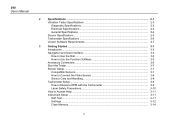
... Users Manual 2 Specifications ...2-1 Vibration Tester Specifications 2-3 Diagnostic Specifications 2-3 Electrical Specifications 2-3 General Specifications 2-4 Sensor Specifications ...2-5 Tachometer Specifications 2-6 Viewer Software Requirements 2-7 3 Getting Started...3-1 Introduction ...3-3 Navigation and User Interface 3-3 How to Use the Dial 3-5 How to Use the Function Softkeys 3-5 Accessory Connectors 3-6 Start the Tester ...3-7 Sensor Setup ...3-7 Compatible Sensors 3-7 How to Connect the Fluke Sensor 3-8 Sensor Care and Handling 3-9 Tachometer Setup...
... Users Manual 2 Specifications ...2-1 Vibration Tester Specifications 2-3 Diagnostic Specifications 2-3 Electrical Specifications 2-3 General Specifications 2-4 Sensor Specifications ...2-5 Tachometer Specifications 2-6 Viewer Software Requirements 2-7 3 Getting Started...3-1 Introduction ...3-3 Navigation and User Interface 3-3 How to Use the Dial 3-5 How to Use the Function Softkeys 3-5 Accessory Connectors 3-6 Start the Tester ...3-7 Sensor Setup ...3-7 Compatible Sensors 3-7 How to Connect the Fluke Sensor 3-8 Sensor Care and Handling 3-9 Tachometer Setup...
User Manual
Page 10
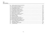
... Machine Setup Functions 4-17 4-14. Existing Machine Setup Functions 4-39 4-24. Application Settings ...5-10 5-3. Copy Machine Setup Functions 4-18 4-15. Change Machine Name Functions 4-19 4-16. Driven Component Options 4-15 4-11. Cited Peak Details ...4-37 4-22. View Machine Setup Utilities 5-28 6-1. Viewer Software Navigation Menus 5-7 5-2. Sensor Placement Functions 4-31 4-20. Drive Options for the Transmission 4-14 4-10. 810 Users Manual 4-9.
... Machine Setup Functions 4-17 4-14. Existing Machine Setup Functions 4-39 4-24. Application Settings ...5-10 5-3. Copy Machine Setup Functions 4-18 4-15. Change Machine Name Functions 4-19 4-16. Driven Component Options 4-15 4-11. Cited Peak Details ...4-37 4-22. View Machine Setup Utilities 5-28 6-1. Viewer Software Navigation Menus 5-7 5-2. Sensor Placement Functions 4-31 4-20. Drive Options for the Transmission 4-14 4-10. 810 Users Manual 4-9.
User Manual
Page 16
810 Users Manual • Context Sensitive Help • 4 GB on-board memory • Data export (via USB connection) for more detailed analysis • Self-test function • Laser tachometer for accurate machine running speed • 100 mV/g TEDS triaxial accelerometer • Data storage and tracking with included Viewer Software • Color LCD display • Languages: English, French, German, Italian, Portuguese...
810 Users Manual • Context Sensitive Help • 4 GB on-board memory • Data export (via USB connection) for more detailed analysis • Self-test function • Laser tachometer for accurate machine running speed • 100 mV/g TEDS triaxial accelerometer • Data storage and tracking with included Viewer Software • Color LCD display • Languages: English, French, German, Italian, Portuguese...
User Manual
Page 28
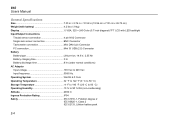
...) Display VGA, 320 × 240 Color (5.7 inch diagonal) TFT LCD with LED backlight Input/Output Connections Triaxial sensor connection 4 pin M12 Connector Single axis sensor connection BNC Connector Tachometer connection Mini DIN 6 pin Connector PC connection Mini 'B' USB (2.0) Connector Battery Battery type Lithium-ion, 14.8 V, 2.55 Ah Battery charging time 3 hr Battery discharge time 8 hr (under normal conditions) AC Adapter Input voltage 100 Vac to 240 Vac Input frequency 50/60 Hz Operating System WinCE 6.0 Core Operating...
...) Display VGA, 320 × 240 Color (5.7 inch diagonal) TFT LCD with LED backlight Input/Output Connections Triaxial sensor connection 4 pin M12 Connector Single axis sensor connection BNC Connector Tachometer connection Mini DIN 6 pin Connector PC connection Mini 'B' USB (2.0) Connector Battery Battery type Lithium-ion, 14.8 V, 2.55 Ah Battery charging time 3 hr Battery discharge time 8 hr (under normal conditions) AC Adapter Input voltage 100 Vac to 240 Vac Input frequency 50/60 Hz Operating System WinCE 6.0 Core Operating...
User Manual
Page 37
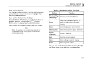
... sounds for an invalid button push. 3 Getting Started Accessory Connectors Table 3-2. Or, push the Dial to Use the Dial The Dial has multiple functions. Done Save keyboard entries. How to select the same function. Push the Dial to move the cursor or highlight. Turn the Dial clockwise or counterclockwise to make a selection. Save Save settings in current display. Table 3-2 lists...
... sounds for an invalid button push. 3 Getting Started Accessory Connectors Table 3-2. Or, push the Dial to Use the Dial The Dial has multiple functions. Done Save keyboard entries. How to select the same function. Push the Dial to move the cursor or highlight. Turn the Dial clockwise or counterclockwise to make a selection. Save Save settings in current display. Table 3-2 lists...
User Manual
Page 39
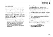
... time you start a test, especially the power line frequency. This technology provides: • Improved results from detailed calibration information • Reduced configuration time without manual data entry • Sensor calibration tracking with the last calibration date stored electronically Compatible Sensors It is compatible with single axis Sensors. Caution Non-Fluke triaxial Sensors are not compatible with the Tester. 3-7 The battery status icon and the set...
... time you start a test, especially the power line frequency. This technology provides: • Improved results from detailed calibration information • Reduced configuration time without manual data entry • Sensor calibration tracking with the last calibration date stored electronically Compatible Sensors It is compatible with single axis Sensors. Caution Non-Fluke triaxial Sensors are not compatible with the Tester. 3-7 The battery status icon and the set...
User Manual
Page 42
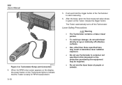
... 2 laser pointer. • To avoid eye damage, do not point laser directly at people or animals. 810 Users Manual gbk06.eps Figure 3-4. Tachometer Setup and Connection 4. The Tester automatically turns off reflective surfaces. • Use, other than those specified here, may be impaired. • Do not aim... the equipment may result in hazardous laser radiation exposure. • Do not use Tachometer in a manner not specified in green on the Tachometer lights to start measuring. 6. When the RPM entry screen appears on the display, the power button on the Tester, release the trigger...
... 2 laser pointer. • To avoid eye damage, do not point laser directly at people or animals. 810 Users Manual gbk06.eps Figure 3-4. Tachometer Setup and Connection 4. The Tester automatically turns off reflective surfaces. • Use, other than those specified here, may be impaired. • Do not aim... the equipment may result in hazardous laser radiation exposure. • Do not use Tachometer in a manner not specified in green on the Tachometer lights to start measuring. 6. When the RPM entry screen appears on the display, the power button on the Tester, release the trigger...

User Manual
Page 43
... user serviceable parts. • When not in use, always place the Tachometer in its protective cover. Push at any time to view specific Help for the Tester includes these pages: • Setup FAQ (Frequently Asked Questions) • Measurement FAQ • Diagnosis FAQ • Glossary • Troubleshooting 3 Getting Started How to Access Help Instrument Setup Push or the Instrument Setup (F3) softkey to display...
... user serviceable parts. • When not in use, always place the Tachometer in its protective cover. Push at any time to view specific Help for the Tester includes these pages: • Setup FAQ (Frequently Asked Questions) • Measurement FAQ • Diagnosis FAQ • Glossary • Troubleshooting 3 Getting Started How to Access Help Instrument Setup Push or the Instrument Setup (F3) softkey to display...
User Manual
Page 64
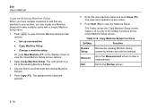
... Setup screen-by-screen and edit the settings. Push Copy (F3). Push to view the New Machine Setup screen options: • Set up new machine • Copy Machine Setup • Change a machine setup Or, push New Machine (F1) in the Startup screen to the Startup screen. 4-18 Exit Exit to view the New Machine Setup screen options. 2. Table 4-14 is a list of the softkey functions for the Copy Machine Setup screen. 810 Users Manual...
... Setup screen-by-screen and edit the settings. Push Copy (F3). Push to view the New Machine Setup screen options: • Set up new machine • Copy Machine Setup • Change a machine setup Or, push New Machine (F1) in the Startup screen to the Startup screen. 4-18 Exit Exit to view the New Machine Setup screen options. 2. Table 4-14 is a list of the softkey functions for the Copy Machine Setup screen. 810 Users Manual...
User Manual
Page 65
... Chapter 5, Viewer Software. 4-19 Refer to creating the Machine Setup for the first time. Once you can create a Machine Setup and transfer it to edit the machine name. For more information about the Machine Setup settings. Push to select a Machine Setup. 5. Use the Dial to view the New Machine Setup screen options: • Set up new machine • Copy Machine Setup • Change a machine setup 2. Exit Exit...
... Chapter 5, Viewer Software. 4-19 Refer to creating the Machine Setup for the first time. Once you can create a Machine Setup and transfer it to edit the machine name. For more information about the Machine Setup settings. Push to select a Machine Setup. 5. Use the Dial to view the New Machine Setup screen options: • Set up new machine • Copy Machine Setup • Change a machine setup 2. Exit Exit...
User Manual
Page 85
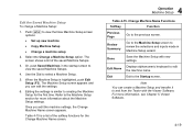
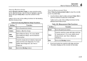
... date and time of the softkey functions for that setup. Table 4-23 is a list of measurement. (For more details about Machine Setup, see the records for the Measurement Date screen. Existing Machine Setup Functions Softkey Function Back Go to the previous screen. Delete Delete a Machine Setup. Table 4-23. Use the Dial to highlight a specific setup and push View (F4) to view the records by the...
... date and time of the softkey functions for that setup. Table 4-23 is a list of measurement. (For more details about Machine Setup, see the records for the Measurement Date screen. Existing Machine Setup Functions Softkey Function Back Go to the previous screen. Delete Delete a Machine Setup. Table 4-23. Use the Dial to highlight a specific setup and push View (F4) to view the records by the...
User Manual
Page 89
... Setup, and diagnosis data, to send to a vibration test consultant. 5 Viewer Software Introduction System Requirements The minimum PC system requirements to use the Viewer software are: • Operating system: Microsoft Windows 2000, Windows XP, Windows Vista, Windows 7, or Windows 8.1 • Minimum 1 GB RAM • One USB port • CD-ROM disk drive PC Connections To connect the computer to the Tester: 1. See Install the Viewer Software. 5-3 Install the supporting software...
... Setup, and diagnosis data, to send to a vibration test consultant. 5 Viewer Software Introduction System Requirements The minimum PC system requirements to use the Viewer software are: • Operating system: Microsoft Windows 2000, Windows XP, Windows Vista, Windows 7, or Windows 8.1 • Minimum 1 GB RAM • One USB port • CD-ROM disk drive PC Connections To connect the computer to the Tester: 1. See Install the Viewer Software. 5-3 Install the supporting software...
User Manual
Page 128
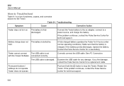
... not turn on. If the problem continues, contact the Fluke Service Center for a replacement cable. hold the button to stop the Tester. If you find damage, contact the Fluke Service Center for technical support. connected correctly. Table 6-1. Battery charge does not The battery is damaged. See PC Connection. Front panel buttons / softkeys do not operate. Restart the Tester. 810 Users Manual How to a power source, and charge the battery. Connect...
... not turn on. If the problem continues, contact the Fluke Service Center for a replacement cable. hold the button to stop the Tester. If you find damage, contact the Fluke Service Center for technical support. connected correctly. Table 6-1. Battery charge does not The battery is damaged. See PC Connection. Front panel buttons / softkeys do not operate. Restart the Tester. 810 Users Manual How to a power source, and charge the battery. Connect...
User Manual
Page 134
... these issues, please contact your Fluke service center. If a component is parallel or perpendicular to the driveshaft using the sensor cable where it exits from each component in the display) as a thick red line in the drive train for Variable Frequency Drives (VFDs) DC Motors and when RPM data is a common diagnostic system error. 810 Users Manual 7. Will the diagnosis be...
... these issues, please contact your Fluke service center. If a component is parallel or perpendicular to the driveshaft using the sensor cable where it exits from each component in the display) as a thick red line in the drive train for Variable Frequency Drives (VFDs) DC Motors and when RPM data is a common diagnostic system error. 810 Users Manual 7. Will the diagnosis be...
User Manual
Page 141
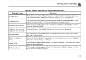
... the calibration date. Contact the Fluke Service Center for technical support. Failed to the current date. See "How to the ac adapter, connect into a power source, and charge the battery. Sensor failure This message shows during a self-test. Tachometer failure This message shows during the self-test. B Warning and Error Messages Display Message Table B-1. Make the measurement again. If the problem...
... the calibration date. Contact the Fluke Service Center for technical support. Failed to the current date. See "How to the ac adapter, connect into a power source, and charge the battery. Sensor failure This message shows during a self-test. Tachometer failure This message shows during the self-test. B Warning and Error Messages Display Message Table B-1. Make the measurement again. If the problem...
Getting Started Guide
Page 7
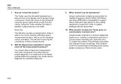
... provides textbased diagnoses, severity levels and possible repair recommendations. To view, print, or download the latest manual supplement, visit http://us.fluke.com/usen/support/manuals. 1 Introduction The Fluke 810 Vibration Tester with diagnostic technology (the Tester) helps you quickly identify and prioritize mechanical problems. With the Tester, you make decisions about mechanical maintenance and use it as a supplement to report on...
... provides textbased diagnoses, severity levels and possible repair recommendations. To view, print, or download the latest manual supplement, visit http://us.fluke.com/usen/support/manuals. 1 Introduction The Fluke 810 Vibration Tester with diagnostic technology (the Tester) helps you quickly identify and prioritize mechanical problems. With the Tester, you make decisions about mechanical maintenance and use it as a supplement to report on...
Getting Started Guide
Page 16
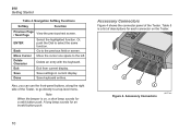
... directly to the left. Accessory Connectors Figure 4 shows the connector panel of descriptions for each connector on , a short beep sounds for an invalid button push. 810 Getting Started Table 4. Done Save keyboard entries. Exit Exit from current display. Save Save settings in current display. A long beep sounds for a valid button push. Navigation Softkey Functions Softkey Function Previous Page / Next Page View the previous/next screen...
... directly to the left. Accessory Connectors Figure 4 shows the connector panel of descriptions for each connector on , a short beep sounds for an invalid button push. 810 Getting Started Table 4. Done Save keyboard entries. Exit Exit from current display. Save Save settings in current display. A long beep sounds for a valid button push. Navigation Softkey Functions Softkey Function Previous Page / Next Page View the previous/next screen...

Getting Started Guide
Page 17
... time you start a test, especially the power line frequency. For charging procedure, see "Instrument Setup" section. 11 It is sufficient battery charge and free memory. Push to the PC using a USB cable Optional connector for at the top of the display. The battery status icon and the set date and time appear at least three hours. Accessory Connectors Item Connector A Tachometer B USB C Sensor D Sensor Description Connects the Tachometer Connects...
... time you start a test, especially the power line frequency. For charging procedure, see "Instrument Setup" section. 11 It is sufficient battery charge and free memory. Push to the PC using a USB cable Optional connector for at the top of the display. The battery status icon and the set date and time appear at least three hours. Accessory Connectors Item Connector A Tachometer B USB C Sensor D Sensor Description Connects the Tachometer Connects...

Getting Started Guide
Page 20
Stop the rotating machine. 3. Tachometer Setup and Connection Attach the Tachometer to the 6-pin DIN connector on the Tachometer lights to start measuring. 9. Attach a piece of reflective tape onto the shaft or other rotating part of the Tachometer to indicate that verifies the RPM ...6. When the RPM entry screen appears on the display, the power button on the Tester. 810 Getting Started How to stop measurement. 11. Release the power button to Measure RPM with the Tachometer To make a Tachometer measurement: 1. The Tester automatically turns off the Tachometer. 14 ...
Stop the rotating machine. 3. Tachometer Setup and Connection Attach the Tachometer to the 6-pin DIN connector on the Tachometer lights to start measuring. 9. Attach a piece of reflective tape onto the shaft or other rotating part of the Tachometer to indicate that verifies the RPM ...6. When the RPM entry screen appears on the display, the power button on the Tester. 810 Getting Started How to stop measurement. 11. Release the power button to Measure RPM with the Tachometer To make a Tachometer measurement: 1. The Tester automatically turns off the Tachometer. 14 ...


