
User Manual
Page 2
... exclusion or limitation of incidental or consequential damages, the limitations and exclusions of this warranty may not apply to the Tachometer and the Sensor but have no risk for repair in transit. Fluke Europe B.V. Following warranty repair, the product will be returned to refund of the purchase price, free of charge repair...
... exclusion or limitation of incidental or consequential damages, the limitations and exclusions of this warranty may not apply to the Tachometer and the Sensor but have no risk for repair in transit. Fluke Europe B.V. Following warranty repair, the product will be returned to refund of the purchase price, free of charge repair...
User Manual
Page 3
Table of Contents Chapter Title Page 1 Overview ...1-1 Introduction ...1-3 Features ...1-3 How to Contact Fluke ...1-4 Safety ...1-4 Rotating Equipment 1-5 Tachometer ...1-5 Heat Sink ...1-6 Symbols ...1-6 Unpack and Inspect...1-7 Storage...1-9 Battery...1-9 Accessories ...1-11 i
Table of Contents Chapter Title Page 1 Overview ...1-1 Introduction ...1-3 Features ...1-3 How to Contact Fluke ...1-4 Safety ...1-4 Rotating Equipment 1-5 Tachometer ...1-5 Heat Sink ...1-6 Symbols ...1-6 Unpack and Inspect...1-7 Storage...1-9 Battery...1-9 Accessories ...1-11 i
User Manual
Page 4
... 3-5 How to Use the Function Softkeys 3-5 Accessory Connectors 3-6 Start the Tester ...3-7 Sensor Setup ...3-7 Compatible Sensors 3-7 How to Connect the Fluke Sensor 3-8 Sensor Care and Handling 3-9 Tachometer Setup ...3-9 How to Measure RPM with the Tachometer 3-9 Laser Safety Precautions 3-10 How to Access Help...3-11 Instrument Setup ...3-11 Self Test...3-11 Settings ...3-12 Clear Memory...
... 3-5 How to Use the Function Softkeys 3-5 Accessory Connectors 3-6 Start the Tester ...3-7 Sensor Setup ...3-7 Compatible Sensors 3-7 How to Connect the Fluke Sensor 3-8 Sensor Care and Handling 3-9 Tachometer Setup ...3-9 How to Measure RPM with the Tachometer 3-9 Laser Safety Precautions 3-10 How to Access Help...3-11 Instrument Setup ...3-11 Self Test...3-11 Settings ...3-12 Clear Memory...

User Manual
Page 11
Items Included with the Tester 1-8 1-2. How to PC Connections ...5-4 6-1. Axes Orientation ...4-22 4-3. Accessory Connectors ...3-6 3-3. Tachometer Setup and Connection 3-10 4-1. Sensor Setup and Connection 3-8 3-4. Sensor Location ...4-21 4-2. Tester to Charge the Battery ...1-10 3-1. Front Panel ...3-3 3-2. Sensor Mounting Options ...4-23 5-1. Battery Replacement ...6-4 ix List of Figures Figure Title Page 1-1.
Items Included with the Tester 1-8 1-2. How to PC Connections ...5-4 6-1. Axes Orientation ...4-22 4-3. Accessory Connectors ...3-6 3-3. Tachometer Setup and Connection 3-10 4-1. Sensor Setup and Connection 3-8 3-4. Sensor Location ...4-21 4-2. Tester to Charge the Battery ...1-10 3-1. Front Panel ...3-3 3-2. Sensor Mounting Options ...4-23 5-1. Battery Replacement ...6-4 ix List of Figures Figure Title Page 1-1.

User Manual
Page 13
Chapter 1 Overview Title Page Introduction ...1-3 Features ...1-3 How to Contact Fluke ...1-4 Safety ...1-4 Rotating Equipment 1-5 Tachometer ...1-5 Heat Sink ...1-6 Symbols ...1-6 Unpack and Inspect...1-7 Storage...1-9 Battery ...1-9 Accessories ...1-11 1-1
Chapter 1 Overview Title Page Introduction ...1-3 Features ...1-3 How to Contact Fluke ...1-4 Safety ...1-4 Rotating Equipment 1-5 Tachometer ...1-5 Heat Sink ...1-6 Symbols ...1-6 Unpack and Inspect...1-7 Storage...1-9 Battery ...1-9 Accessories ...1-11 1-1
User Manual
Page 16
.... To register your product, visit http://register.fluke.com. 810 Users Manual • Context Sensitive Help • 4 GB on-board memory • Data export (via USB connection) for more detailed analysis • Self-test function • Laser tachometer for accurate machine running speed • 100 mV/g TEDS triaxial accelerometer • Data storage...
.... To register your product, visit http://register.fluke.com. 810 Users Manual • Context Sensitive Help • 4 GB on-board memory • Data export (via USB connection) for more detailed analysis • Self-test function • Laser tachometer for accurate machine running speed • 100 mV/g TEDS triaxial accelerometer • Data storage...
User Manual
Page 17
...; When not in use the Tester, inspect the case. gbk15.eps 1-5 Before you use , always place in protective cover. Tachometer Warning To avoid personal injury or damage to the Tachometer: • Do not point laser beam directly at eyes. • Do not operate around explosive gas, vapor or dust. •...
...; When not in use the Tester, inspect the case. gbk15.eps 1-5 Before you use , always place in protective cover. Tachometer Warning To avoid personal injury or damage to the Tachometer: • Do not point laser beam directly at eyes. • Do not operate around explosive gas, vapor or dust. •...

User Manual
Page 19
... purchase of the Tester: Vibration Tester Storage Case Smart Battery Pack Smart Battery Pack Charger and Adapters Shoulder Strap Tachometer and Pouch Sensor Sensor Magnet Mount Sensor Quick Disconnect Cable Sensor Mounting Pads (10-pack) Adhesive Mini USB to...
... purchase of the Tester: Vibration Tester Storage Case Smart Battery Pack Smart Battery Pack Charger and Adapters Shoulder Strap Tachometer and Pouch Sensor Sensor Magnet Mount Sensor Quick Disconnect Cable Sensor Mounting Pads (10-pack) Adhesive Mini USB to...

User Manual
Page 23
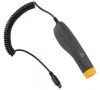
Accessories Model Description Part Number 810T Tachometer 3530819 810S Sensor 3530828 810QDC Quick Disconnect Cable 3530837 SBP810 Smart Battery Pack 3530843 810SMM Sensor Magnet Mount 3530862 810SMP Sensor Mounting Pads 3530855 Note The maximum cable run or you may get unexpected results. 1-11 1 Overview Accessories Accessories Table 1-2 lists the accessories that are available and sold separately for the Tester. Do not combine cables to exceed the maximum cable run is 20 ft (6 m). Table 1-2.
Accessories Model Description Part Number 810T Tachometer 3530819 810S Sensor 3530828 810QDC Quick Disconnect Cable 3530837 SBP810 Smart Battery Pack 3530843 810SMM Sensor Magnet Mount 3530862 810SMP Sensor Mounting Pads 3530855 Note The maximum cable run or you may get unexpected results. 1-11 1 Overview Accessories Accessories Table 1-2 lists the accessories that are available and sold separately for the Tester. Do not combine cables to exceed the maximum cable run is 20 ft (6 m). Table 1-2.

User Manual
Page 25
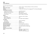
Chapter 2 Specifications Title Page Vibration Tester Specifications 2-3 Diagnostic Specifications 2-3 Electrical Specifications 2-3 General Specifications 2-4 Sensor Specifications...2-5 Tachometer Specifications 2-6 Viewer Software Requirements 2-7 2-1
Chapter 2 Specifications Title Page Vibration Tester Specifications 2-3 Diagnostic Specifications 2-3 Electrical Specifications 2-3 General Specifications 2-4 Sensor Specifications...2-5 Tachometer Specifications 2-6 Viewer Software Requirements 2-7 2-1
User Manual
Page 28
... × 240 Color (5.7 inch diagonal) TFT LCD with LED backlight Input/Output Connections Triaxial sensor connection 4 pin M12 Connector Single axis sensor connection BNC Connector Tachometer connection Mini DIN 6 pin Connector PC connection Mini 'B' USB (2.0) Connector Battery Battery type Lithium-ion, 14.8 V, 2.55 Ah Battery charging time 3 hr Battery discharge time...
... × 240 Color (5.7 inch diagonal) TFT LCD with LED backlight Input/Output Connections Triaxial sensor connection 4 pin M12 Connector Single axis sensor connection BNC Connector Tachometer connection Mini DIN 6 pin Connector PC connection Mini 'B' USB (2.0) Connector Battery Battery type Lithium-ion, 14.8 V, 2.55 Ah Battery charging time 3 hr Battery discharge time...

User Manual
Page 30
... Shock Limit 5000 g peak Electromagnetic Sensitivity, Equivalent g.......... 100 μg/gauss Sealing Hermetic Temperature Range 58 °F to 248 °F (-50 °C to 120 °C) ±7 % Tachometer Specifications Dimensions 1.125 in x 4.80 in (2.86 cm x 12.19 cm) Weight 3.4 oz (96 gr) with cable Power Powered by Vibration Tester Detection Laser Diode...
... Shock Limit 5000 g peak Electromagnetic Sensitivity, Equivalent g.......... 100 μg/gauss Sealing Hermetic Temperature Range 58 °F to 248 °F (-50 °C to 120 °C) ±7 % Tachometer Specifications Dimensions 1.125 in x 4.80 in (2.86 cm x 12.19 cm) Weight 3.4 oz (96 gr) with cable Power Powered by Vibration Tester Detection Laser Diode...

User Manual
Page 31
2 Specifications Viewer Software Requirements Interface 6 Pin Mini DIN Cable Length 19.586 in (50 cm) Tachometer Accessories Reflective tape 0.59 in × 20.67 in (1.5 cm x 52.5 cm) Viewer Software Requirements Minimum Hardware 1 GB RAM Operating System Windows XP, Vista, Windows 7, Windows 8.1 2-7
2 Specifications Viewer Software Requirements Interface 6 Pin Mini DIN Cable Length 19.586 in (50 cm) Tachometer Accessories Reflective tape 0.59 in × 20.67 in (1.5 cm x 52.5 cm) Viewer Software Requirements Minimum Hardware 1 GB RAM Operating System Windows XP, Vista, Windows 7, Windows 8.1 2-7
User Manual
Page 33
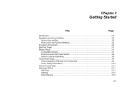
Chapter 3 Getting Started Title Page Introduction ...3-3 Navigation and User Interface 3-3 How to Use the Dial 3-5 How to Use the Function Softkeys 3-5 Accessory Connectors 3-6 Start the Tester ...3-7 Sensor Setup ...3-7 Compatible Sensors 3-7 How to Connect the Fluke Sensor 3-8 Sensor Care and Handling 3-9 Tachometer Setup...3-9 How to Measure RPM with the Tachometer 3-9 Laser Safety Precautions 3-10 How to Access Help ...3-11 Instrument Setup ...3-11 Self Test ...3-11 Settings ...3-12 Clear Memory ...3-14 3-1
Chapter 3 Getting Started Title Page Introduction ...3-3 Navigation and User Interface 3-3 How to Use the Dial 3-5 How to Use the Function Softkeys 3-5 Accessory Connectors 3-6 Start the Tester ...3-7 Sensor Setup ...3-7 Compatible Sensors 3-7 How to Connect the Fluke Sensor 3-8 Sensor Care and Handling 3-9 Tachometer Setup...3-9 How to Measure RPM with the Tachometer 3-9 Laser Safety Precautions 3-10 How to Access Help ...3-11 Instrument Setup ...3-11 Self Test ...3-11 Settings ...3-12 Clear Memory ...3-14 3-1
User Manual
Page 38
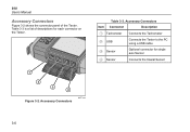
Accessory Connectors Connector Description Tachometer Connects the Tachometer USB Connects the Tester to the PC using a USB cable Sensor Optional connector for each connector on the Tester. 1 2 3 4 Figure 3-2. Accessory Connectors gbk01.eps Item Table 3-3. 810 Users Manual Accessory Connectors Figure 3-2 shows the connector panel of descriptions for single axis Sensor Sensor Connects the triaxial Sensor 3-6 Table 3-3 is a list of the Tester.
Accessory Connectors Connector Description Tachometer Connects the Tachometer USB Connects the Tester to the PC using a USB cable Sensor Optional connector for each connector on the Tester. 1 2 3 4 Figure 3-2. Accessory Connectors gbk01.eps Item Table 3-3. 810 Users Manual Accessory Connectors Figure 3-2 shows the connector panel of descriptions for single axis Sensor Sensor Connects the triaxial Sensor 3-6 Table 3-3 is a list of the Tester.

User Manual
Page 41
...other rotating part of the rotating machine under varying load conditions. Note Fluke recommends the use the non-contact type laser Tachometer to measure the RPM. Hold the Tachometer firmly and steady. 3-9 Attach the Tachometer to the machine, stop the rotating machine. If the RPM is ...inside the Sensor, do not drop. Sensor Care and Handling Caution • To prevent damage to Measure RPM with the Tachometer To make a Tachometer measurement: 1. A faulty Sensor significantly affects the diagnostic quality. • Do not pull or force the cable while attaching or removing ...
...other rotating part of the rotating machine under varying load conditions. Note Fluke recommends the use the non-contact type laser Tachometer to measure the RPM. Hold the Tachometer firmly and steady. 3-9 Attach the Tachometer to the machine, stop the rotating machine. If the RPM is ...inside the Sensor, do not drop. Sensor Care and Handling Caution • To prevent damage to Measure RPM with the Tachometer To make a Tachometer measurement: 1. A faulty Sensor significantly affects the diagnostic quality. • Do not pull or force the cable while attaching or removing ...
User Manual
Page 42
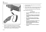
... those specified here, may be impaired. • Do not aim the laser beam at people or animals. Push and hold the trigger button of the Tachometer to indicate that the Tester is ready for RPM measurement. 3-10 5. Laser Safety Precautions Warning • The... a Class 2 laser pointer. • To avoid eye damage, do not point laser directly at eye or indirectly off the Tachometer. 810 Users Manual gbk06.eps Figure 3-4. After the beep, when the final measured value shows in this document or the protection provided by the equipment ...
... those specified here, may be impaired. • Do not aim the laser beam at people or animals. Push and hold the trigger button of the Tachometer to indicate that the Tester is ready for RPM measurement. 3-10 5. Laser Safety Precautions Warning • The... a Class 2 laser pointer. • To avoid eye damage, do not point laser directly at eye or indirectly off the Tachometer. 810 Users Manual gbk06.eps Figure 3-4. After the beep, when the final measured value shows in this document or the protection provided by the equipment ...

User Manual
Page 43
... no user serviceable parts. • When not in use, always place the Tachometer in its protective cover. Push at any time to view specific Help for ... The Self test option tests the internal modules of children. • Do not open the Tachometer. Push the Done softkey to go back to Access Help The Tester has context sensitive Help. Caution ...• Keep the Tachometer out of the reach of the Tester. How to Instrument Setup. Note If the self-test fails, contact Fluke Service. 3-11 Push the Dial or Enter (F3) to highlight...
... no user serviceable parts. • When not in use, always place the Tachometer in its protective cover. Push at any time to view specific Help for ... The Self test option tests the internal modules of children. • Do not open the Tachometer. Push the Done softkey to go back to Access Help The Tester has context sensitive Help. Caution ...• Keep the Tachometer out of the reach of the Tester. How to Instrument Setup. Note If the self-test fails, contact Fluke Service. 3-11 Push the Dial or Enter (F3) to highlight...

User Manual
Page 51
... or kilowatt (kW) input is important to activate the combo box. 2. To make a selection: 1. Push Enter to obtain the correct RPM using a tachometer. It is required for any Machine Setup option. Measuring VFDs requires entering RPM at the time of measurement (instead of relying on the component you... (Driver) Information Entering an accurate running speed (RPM) is a combination of existing options. To obtain an accurate RPM value, use the Tachometer provided with the Tester or obtain the frequency value from the list of a drop-down list or list box. For consistent diagnoses over time...
... or kilowatt (kW) input is important to activate the combo box. 2. To make a selection: 1. Push Enter to obtain the correct RPM using a tachometer. It is required for any Machine Setup option. Measuring VFDs requires entering RPM at the time of measurement (instead of relying on the component you... (Driver) Information Entering an accurate running speed (RPM) is a combination of existing options. To obtain an accurate RPM value, use the Tachometer provided with the Tester or obtain the frequency value from the list of a drop-down list or list box. For consistent diagnoses over time...

User Manual
Page 52
Motor Input Options Option Description AC Select motor type DC Select the motor type of the motor. Use the Tachometer to access the numeric keyboard. Enter the HP (Horsepower) or the kW of the machine under test. Motor bearing type Roller Journal Select the bearing ...
Motor Input Options Option Description AC Select motor type DC Select the motor type of the motor. Use the Tachometer to access the numeric keyboard. Enter the HP (Horsepower) or the kW of the machine under test. Motor bearing type Roller Journal Select the bearing ...