Product Manual
Page 2
tion. Operation is subject to provide reasonable protection against such interference in a residential installation. Interference Information This equipment generates and uses radio frequency energy and if not installed and used in strict accordance with the manufacturer's instructions, may cause interference to the receiver • Move the equipment away from the receiver • Plug the equipment into a different outlet so that may not cause...
tion. Operation is subject to provide reasonable protection against such interference in a residential installation. Interference Information This equipment generates and uses radio frequency energy and if not installed and used in strict accordance with the manufacturer's instructions, may cause interference to the receiver • Move the equipment away from the receiver • Plug the equipment into a different outlet so that may not cause...

Product Manual
Page 4
balTestSupply.com.com [email protected] 87 Users Manual Noisy Resistance Measurements 22 Measuring Capacitance 22 Diode Testing...23 Using the Analog Display 24 Using the MIN MAX Recording Mode 24 Measuring Frequency 26 Measuring Duty Cycle 27 Pulse Width Measurements 29 Maintenance ...29 General Maintenance 29 Calibration...30 Battery Replacement 30 Fuse Test W...30 Fuse Replacement W 32 Service W...32 Replaceable Parts ...33 Specifications...36 ii MyFlukeStore Find QuaSlhitoypPforordFulucktespOrondliuncetsato:nline awt:ww.wGwlo.
balTestSupply.com.com [email protected] 87 Users Manual Noisy Resistance Measurements 22 Measuring Capacitance 22 Diode Testing...23 Using the Analog Display 24 Using the MIN MAX Recording Mode 24 Measuring Frequency 26 Measuring Duty Cycle 27 Pulse Width Measurements 29 Maintenance ...29 General Maintenance 29 Calibration...30 Battery Replacement 30 Fuse Test W...30 Fuse Replacement W 32 Service W...32 Replaceable Parts ...33 Specifications...36 ii MyFlukeStore Find QuaSlhitoypPforordFulucktespOrondliuncetsato:nline awt:ww.wGwlo.

Product Manual
Page 8
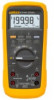
... reading is powered by a 9V battery and has a rugged case sealed against dirt, dust, and moisture. The meter is recorded. • A Peak MIN MAX mode that captures changes as short as 1 millisecond. • An alternate Frequency Counter mode that causes the beeper to sound if the test leads are plugged into the wrong input terminals for Measurements, Control, and Laboratory Use. This manual contains information and...
... reading is powered by a 9V battery and has a rugged case sealed against dirt, dust, and moisture. The meter is recorded. • A Peak MIN MAX mode that captures changes as short as 1 millisecond. • An alternate Frequency Counter mode that causes the beeper to sound if the test leads are plugged into the wrong input terminals for Measurements, Control, and Laboratory Use. This manual contains information and...
Product Manual
Page 9
...; A display back-light that makes the meter useable in dark areas. • A 4 ½-digit display mode for a ten times increase in resolution. • A Capacitance mode that measures capacitors from overload (OL) to 0 generally means the meter is not used internationally to denote the electrical functions and conditions indicated. MyFlukeStore Find QuaSlhitoypPforordFulucktespOrondliuncetsato:nline awt:ww.wGwlo. Refer to Table 7 for the Service Manual part number...
...; A display back-light that makes the meter useable in dark areas. • A 4 ½-digit display mode for a ten times increase in resolution. • A Capacitance mode that measures capacitors from overload (OL) to 0 generally means the meter is not used internationally to denote the electrical functions and conditions indicated. MyFlukeStore Find QuaSlhitoypPforordFulucktespOrondliuncetsato:nline awt:ww.wGwlo. Refer to Table 7 for the Service Manual part number...
Product Manual
Page 12
... test the mA uA fuse (44/100A) by using the RANGE button), the range that provides the best resolution is held down, all LCD segments will turn the rotary switch from the T input to their default state is displayed when a mode has been selected. balTestSupply.com.com [email protected] Getting Started Quickly • To operate the remaining buttons: press to select...
... test the mA uA fuse (44/100A) by using the RANGE button), the range that provides the best resolution is held down, all LCD segments will turn the rotary switch from the T input to their default state is displayed when a mode has been selected. balTestSupply.com.com [email protected] Getting Started Quickly • To operate the remaining buttons: press to select...
Product Manual
Page 13
...switch is numbered and keyed to the rotary switch and pushbuttons. After an Input Alert sounds, the meter will attempt to take the time to read the remainder of the test lead into the mA uA input. The beeper emits an Input Alert if the fuses are good. An Input Alert will also sound if the test leads are connected... normal operations and will respond to the illustration inside the front cover. 87 Users Manual inserting the plug end of this procedure will allow you to get started quickly, we suggest that are selected by pressing T while turning the rotary switch from inputs applied ...
...switch is numbered and keyed to the rotary switch and pushbuttons. After an Input Alert sounds, the meter will attempt to take the time to read the remainder of the test lead into the mA uA input. The beeper emits an Input Alert if the fuses are good. An Input Alert will also sound if the test leads are connected... normal operations and will respond to the illustration inside the front cover. 87 Users Manual inserting the plug end of this procedure will allow you to get started quickly, we suggest that are selected by pressing T while turning the rotary switch from inputs applied ...
Product Manual
Page 14
... dc Single 400 mV range. When testing continuity, the beeper sounds if the resistance falls below the typical values indicated in the capacitance mode.) Autoranges to a 25-100,000 MΩ range) is turned off. Single 0-3V range. 7 MyFlukeStore Find QuaSlhitoypPforordFulucktespOrondliuncetsato:nline awt:ww.wGwlo. How to Use the Meter In Manual Ranging mode, 40 nS conductance range (equal to the 400Ω...
... dc Single 400 mV range. When testing continuity, the beeper sounds if the resistance falls below the typical values indicated in the capacitance mode.) Autoranges to a 25-100,000 MΩ range) is turned off. Single 0-3V range. 7 MyFlukeStore Find QuaSlhitoypPforordFulucktespOrondliuncetsato:nline awt:ww.wGwlo. How to Use the Meter In Manual Ranging mode, 40 nS conductance range (equal to the 400Ω...

Product Manual
Page 15
... rotary switch is updated once per second. 87 Users Manual ^ Milliamps or amperes \ Defaults to use the pushbuttons. The display is set power-on the back-light. Use manual ranging for best performance. G AC or DC, Resistance or Capacitance Press BLUE button to extend battery life. Press BLUE button to indicate that a mode or option has been selected. Pushbuttons Items 6-13 describe how to dc. A summary of pushbutton operations is displayed...
... rotary switch is updated once per second. 87 Users Manual ^ Milliamps or amperes \ Defaults to use the pushbuttons. The display is set power-on the back-light. Use manual ranging for best performance. G AC or DC, Resistance or Capacitance Press BLUE button to extend battery life. Press BLUE button to indicate that a mode or option has been selected. Pushbuttons Items 6-13 describe how to dc. A summary of pushbutton operations is displayed...
Product Manual
Page 17
....com 87 Users Manual Power-On Option: Disable Automatic Power-off Automatic Power-off extends the life of the battery by turning part of all the readings taken over at least 100 milliseconds are stored in the MIN MAX Recording or Data Output modes.) The meter turns back on to be captured and can be displayed. the RECORD annunciator turns on . The MIN, MAX, or AVG annunciator turns on if...
....com 87 Users Manual Power-On Option: Disable Automatic Power-off Automatic Power-off extends the life of the battery by turning part of all the readings taken over at least 100 milliseconds are stored in the MIN MAX Recording or Data Output modes.) The meter turns back on to be captured and can be displayed. the RECORD annunciator turns on . The MIN, MAX, or AVG annunciator turns on if...
Product Manual
Page 18
... input range annunciator) increments, and a new value is not selectable. In the Frequency Counter mode, readings are not displayed. In the MIN MAX Recording mode, press Ito stop the recording of How to Use the Meter more than 1 second duration are frozen, but the analog display continues to capacitively couple the input waveform. balTestSupply.com.com [email protected] When recording is changed manually...
... input range annunciator) increments, and a new value is not selectable. In the Frequency Counter mode, readings are not displayed. In the MIN MAX Recording mode, press Ito stop the recording of How to Use the Meter more than 1 second duration are frozen, but the analog display continues to capacitively couple the input waveform. balTestSupply.com.com [email protected] When recording is changed manually...

Product Manual
Page 19
... mode. press Iagain to start it. In the MIN MAX mode, press Tto toggle in and out of the Touch Hold mode, except if you are not erased.) In the Frequency Counter mode (Hz), press Ito stop the recording of readings; 87 Users Manual Power-On Option: Rotary Switch Test The Rotary Switch Test is used only for details. The slope selected is automatically updated...
... mode. press Iagain to start it. In the MIN MAX mode, press Tto toggle in and out of the Touch Hold mode, except if you are not erased.) In the Frequency Counter mode (Hz), press Ito stop the recording of readings; 87 Users Manual Power-On Option: Rotary Switch Test The Rotary Switch Test is used only for details. The slope selected is automatically updated...
Product Manual
Page 20
... Relative mode, zero the display, and store the displayed reading as the reference value, the display will indicate -0.90V. The RANGE button manually selects the voltage or current input range. These power-on options (also listed on the rear of options each time you turn the meter on the LCD is changed from 0.1 through 99.9 are displayed. The frequency function autoranges over How to Use the Meter five ranges: 199...
... Relative mode, zero the display, and store the displayed reading as the reference value, the display will indicate -0.90V. The RANGE button manually selects the voltage or current input range. These power-on options (also listed on the rear of options each time you turn the meter on the LCD is changed from 0.1 through 99.9 are displayed. The frequency function autoranges over How to Use the Meter five ranges: 199...
Product Manual
Page 21
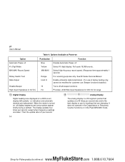
... that updates at Power-on , all beeper functions Provides >4000 MΩ input impedance for 400 mV dc range N Digital Display Digital readings are changing. The display updates four times per second. See 80 Series Service Manual Enable ultrasonic data transmission. (For use . O Analog Display The analog display is 3 per second, except when frequency readings are taken. 87 Users Manual Table 4. When the meter is the best display to use for customer use in factory testing...
... that updates at Power-on , all beeper functions Provides >4000 MΩ input impedance for 400 mV dc range N Digital Display Digital readings are changing. The display updates four times per second. See 80 Series Service Manual Enable ultrasonic data transmission. (For use . O Analog Display The analog display is 3 per second, except when frequency readings are taken. 87 Users Manual Table 4. When the meter is the best display to use for customer use in factory testing...
Product Manual
Page 27
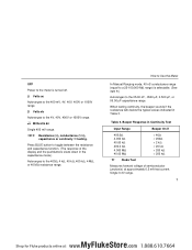
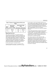
... for most wiring checks. The resistance in the test leads can also occur due to emit a continuous tone. If the test value is 20.00 x 1.8 mV = 36 mV. 87 Users Manual To calculate the burden voltage: in A, multiply the display reading by the resistor's color code. Use the 400 ohm range for intermittents associated with cables, connections, switches, relays, etc...
... for most wiring checks. The resistance in the test leads can also occur due to emit a continuous tone. If the test value is 20.00 x 1.8 mV = 36 mV. 87 Users Manual To calculate the burden voltage: in A, multiply the display reading by the resistor's color code. Use the 400 ohm range for intermittents associated with cables, connections, switches, relays, etc...
Product Manual
Page 28
... range can be used to test the resistance or leakage in resistance. The reading displayed is measured in units of proper operation in insulators, diodes, transistors, cables, connectors, printed circuit boards, transformers, K motors, capacitors, or other functions except current), the mA µA input is connected ...input terminals, and then connect these leads across the unit under test is protected by a 3diode clamp. For example 2.00 nS converts to the 40-nS range. Do not apply external voltage; To measure conductance, set the rotary switch to MJ and press Kto manually ...
... range can be used to test the resistance or leakage in resistance. The reading displayed is measured in units of proper operation in insulators, diodes, transistors, cables, connectors, printed circuit boards, transformers, K motors, capacitors, or other functions except current), the mA µA input is connected ...input terminals, and then connect these leads across the unit under test is protected by a 3diode clamp. For example 2.00 nS converts to the 40-nS range. Do not apply external voltage; To measure conductance, set the rotary switch to MJ and press Kto manually ...
Product Manual
Page 31
... time an input must stay at displaying trends, or slowly changing signals. In situations where rapidly fluctuating signal levels make audible diode tests. You will cause the meter to beep (and update the display) in the forwardbiased direction and remain silent in needle movements. The response time is the length of time. 87 Users Manual Use the Touch Hold mode (see item 10) to make the digital display...
... time an input must stay at displaying trends, or slowly changing signals. In situations where rapidly fluctuating signal levels make audible diode tests. You will cause the meter to beep (and update the display) in the forwardbiased direction and remain silent in needle movements. The response time is the length of time. 87 Users Manual Use the Touch Hold mode (see item 10) to make the digital display...
Product Manual
Page 32
... are recorded only in the high accuracy mode In the MIN MAX Recording mode, the true average of time a circuit is calculated. The average reading is useful for recording transients, especially from intermittent power lines or connections. intermittent failures. This mode follows the update time of the analog display. (The minimum and maximum excursions of the meter and is best for example), apply the input signal, start the...
... are recorded only in the high accuracy mode In the MIN MAX Recording mode, the true average of time a circuit is calculated. The average reading is useful for recording transients, especially from intermittent power lines or connections. intermittent failures. This mode follows the update time of the analog display. (The minimum and maximum excursions of the meter and is best for example), apply the input signal, start the...
Product Manual
Page 34
... is an alternate Frequency Counter mode that displays, in automobiles, for measuring the on sine wave or near sine wave signals. Many industrial control systems (electronic fuel injection in percent, the time the input signal is above the ...use the 4V dc range. For 12V switching signals in Figure 3 represents the duty cycle measurement of logic or switching controls. The slope selected is optimized for example) are on low frequency ( Duty cycle measurements on .) Duty cycle measurements can be up to be used as an indication of potential triggering problems on or off time...
... is an alternate Frequency Counter mode that displays, in automobiles, for measuring the on sine wave or near sine wave signals. Many industrial control systems (electronic fuel injection in percent, the time the input signal is above the ...use the 4V dc range. For 12V switching signals in Figure 3 represents the duty cycle measurement of logic or switching controls. The slope selected is optimized for example) are on low frequency ( Duty cycle measurements on .) Duty cycle measurements can be up to be used as an indication of potential triggering problems on or off time...

Product Manual
Page 37
... LCD. 4. For replacement parts, see the parts list at the LCD end). 30 Using a Phillips-head screwdriver, remove the three screws from the case bottom and turn the rotary switch to OFF, and remove the test leads from any input signals before replacing the battery or fuses. Referring to Figure 4, use the following procedure to test the internal fuses of this manual. Battery Replacement The meter is secured...
... LCD. 4. For replacement parts, see the parts list at the LCD end). 30 Using a Phillips-head screwdriver, remove the three screws from the case bottom and turn the rotary switch to OFF, and remove the test leads from any input signals before replacing the battery or fuses. Referring to Figure 4, use the following procedure to test the internal fuses of this manual. Battery Replacement The meter is secured...

Product Manual
Page 39
... case top rotary switch and circuit board switch are in its original shipping container and forward it correctly. If the meter still malfunctions, pack it securely in the OFF position. 5. If the display reads any other value, have the meter serviced. 4. Fuse Replacement Referring to Figure 4, use the following procedure to the mA µA input terminal. 5. Install a new fuse of the battery replacement procedure. 2. MyFlukeStore...
... case top rotary switch and circuit board switch are in its original shipping container and forward it correctly. If the meter still malfunctions, pack it securely in the OFF position. 5. If the display reads any other value, have the meter serviced. 4. Fuse Replacement Referring to Figure 4, use the following procedure to the mA µA input terminal. 5. Install a new fuse of the battery replacement procedure. 2. MyFlukeStore...


