
FE 83V & 87V Users Manual
Page 4
80 Series V Users Manual Measuring AC or DC Current 24 Measuring Frequency 27 Measuring Duty Cycle 29 Determining Pulse Width 30 Bar Graph...30 Zoom Mode (Power Up Option Only 31 Uses for the Zoom Mode 31 HiRes Mode (Model 87) ...31 MIN MAX Recording Mode 32 Smooth Feature (Power Up Option Only 32 AutoHOLD Mode...34 Relative Mode ...34 Maintenance...35 General Maintenance...35 Fuse Test ...35 Replacing the Battery...36 Replacing the Fuses ...37 Service and Parts...37 Specifications ...43 Detailed Specifications 44 ii
80 Series V Users Manual Measuring AC or DC Current 24 Measuring Frequency 27 Measuring Duty Cycle 29 Determining Pulse Width 30 Bar Graph...30 Zoom Mode (Power Up Option Only 31 Uses for the Zoom Mode 31 HiRes Mode (Model 87) ...31 MIN MAX Recording Mode 32 Smooth Feature (Power Up Option Only 32 AutoHOLD Mode...34 Relative Mode ...34 Maintenance...35 General Maintenance...35 Fuse Test ...35 Replacing the Battery...36 Replacing the Fuses ...37 Service and Parts...37 Specifications ...43 Detailed Specifications 44 ii

FE 83V & 87V Users Manual
Page 7
List of Duty Cycle Measurements 29 10. Testing for Continuity...17 5. Replaceable Parts ...41 v Measuring AC and DC Voltage 14 3. Testing a Diode...23 8. Battery and Fuse Replacement 38 12. Measuring Current...25 9. Testing the Current Fuses ...36 11. Display Features (Model 87) ...11 2. Measuring Resistance ...19 6. Measuring Capacitance...21 7. Components of Figures Figure Title Page 1. Low Pass Filter ...15 4.
List of Duty Cycle Measurements 29 10. Testing for Continuity...17 5. Replaceable Parts ...41 v Measuring AC and DC Voltage 14 3. Testing a Diode...23 8. Battery and Fuse Replacement 38 12. Measuring Current...25 9. Testing the Current Fuses ...36 11. Display Features (Model 87) ...11 2. Measuring Resistance ...19 6. Measuring Capacitance...21 7. Components of Figures Figure Title Page 1. Low Pass Filter ...15 4.

FE 83V & 87V Users Manual
Page 11
...• Do not apply more than what is indicated may be present. These voltages pose a shock hazard. • Use only the replacement fuses specified by the manual. • Use the proper terminals, function, and range for damaged insulation or exposed metal. Remember to detect the possible ...presence of hazardous voltages. Replace damaged test leads before you use the Low Pass Filter option to power the Meter. • When servicing the Meter, use the Meter if it ...
...• Do not apply more than what is indicated may be present. These voltages pose a shock hazard. • Use only the replacement fuses specified by the manual. • Use the proper terminals, function, and range for damaged insulation or exposed metal. Remember to detect the possible ...presence of hazardous voltages. Replace damaged test leads before you use the Low Pass Filter option to power the Meter. • When servicing the Meter, use the Meter if it ...

FE 83V & 87V Users Manual
Page 12
80 Series V Users Manual WCaution To avoid possible damage to the Meter or to the equipment under test, follow these guidelines: • Disconnect circuit power and discharge all high-voltage capacitors before testing resistance, continuity, diodes, or capacitance. • Use the proper terminals, function, and range for all measurements. • Before measuring current, check the Meter's fuses. (See "Fuse Test".) 4
80 Series V Users Manual WCaution To avoid possible damage to the Meter or to the equipment under test, follow these guidelines: • Disconnect circuit power and discharge all high-voltage capacitors before testing resistance, continuity, diodes, or capacitance. • Use the proper terminals, function, and range for all measurements. • Before measuring current, check the Meter's fuses. (See "Fuse Test".) 4

FE 83V & 87V Users Manual
Page 13
Low battery when displayed. Continuity test or continuity beeper tone. $ Conforms to protect against transients in equipment in large buildings. Battery. Safety Information Table 1. G Diode s ...Association directives. Important information. W M R Risk of Danger. Electrical Symbols B AC (Alternating Current) F DC (Direct Current) X Hazardous voltage J I P Earth ground Fuse Conforms to protect against transients from the primary supply level, such as distribution panels, feeders and short branch circuits, and lighting systems in fixedequipment installations...
Low battery when displayed. Continuity test or continuity beeper tone. $ Conforms to protect against transients in equipment in large buildings. Battery. Safety Information Table 1. G Diode s ...Association directives. Important information. W M R Risk of Danger. Electrical Symbols B AC (Alternating Current) F DC (Direct Current) X Hazardous voltage J I P Earth ground Fuse Conforms to protect against transients from the primary supply level, such as distribution panels, feeders and short branch circuits, and lighting systems in fixedequipment installations...

FE 83V & 87V Users Manual
Page 21
...Power-Off The Meter automatically turns off if you by making a chirping sound and the display flashes "LEAd". Input Alert Feature If a test lead is plugged into the mA/µA or A terminal, but the rotary switch is plugged into a current terminal. To select the 600.0 ...Meter on activates a power-up options. This warning is intended to measure voltage, continuity, resistance, capacitance, or diode values when the leads are testing and blow the Meter's fuse. Measuring AC and DC Voltage Model 87 features true rms readings, which are 600.0 mV, 6.000 V, 60.00 V, 600.0 V, and ...
...Power-Off The Meter automatically turns off if you by making a chirping sound and the display flashes "LEAd". Input Alert Feature If a test lead is plugged into the mA/µA or A terminal, but the rotary switch is plugged into a current terminal. To select the 600.0 ...Meter on activates a power-up options. This warning is intended to measure voltage, continuity, resistance, capacitance, or diode values when the leads are testing and blow the Meter's fuse. Measuring AC and DC Voltage Model 87 features true rms readings, which are 600.0 mV, 6.000 V, 60.00 V, 600.0 V, and ...
FE 83V & 87V Users Manual
Page 25
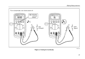
For in-circuit tests, turn circuit power off. 87 V TRUE RMS MULTIMETER 4½ DIGITS 1 Second MIN MAX Peak MIN MAX ˚C/˚F RANGE REL mV V AutoHOLD Hz % mA A LO V A OFF A mA A COM V 10A MAX FUSED 400mA FUSED Activates continuity beeper ON (closed) 87 V TRUE RMS MULTIMETER MIN MAX Peak MIN MAX 4½ DIGITS 1 Second ˚C/˚F RANGE REL mV V AutoHOLD Hz % mA A LO V A OFF A mA A COM V 10A MAX FUSED 400mA FUSED Making Measurements OFF (open) Figure 4. Testing for Continuity aom4f.eps 17
For in-circuit tests, turn circuit power off. 87 V TRUE RMS MULTIMETER 4½ DIGITS 1 Second MIN MAX Peak MIN MAX ˚C/˚F RANGE REL mV V AutoHOLD Hz % mA A LO V A OFF A mA A COM V 10A MAX FUSED 400mA FUSED Activates continuity beeper ON (closed) 87 V TRUE RMS MULTIMETER MIN MAX Peak MIN MAX 4½ DIGITS 1 Second ˚C/˚F RANGE REL mV V AutoHOLD Hz % mA A LO V A OFF A mA A COM V 10A MAX FUSED 400mA FUSED Making Measurements OFF (open) Figure 4. Testing for Continuity aom4f.eps 17

FE 83V & 87V Users Manual
Page 29
...µF. To improve the accuracy of measurements less than 1000 nF, use the relative (REL) mode to the equipment under test, disconnect circuit power and discharge all high-voltage capacitors before measuring capacitance. Making Measurements Select Capacitance 87 V TRUE RMS MULTIMETER MIN...DIGITS 1 Second ˚C/˚F RANGE REL mV V AutoHOLD Hz % mA A LO V A OFF A mA A COM V 10A MAX FUSED 400mA FUSED + Figure 6. Measuring Capacitance aom10f.eps 21 To measure capacitance, set up the Meter as shown in Figure 6. Measuring Capacitance WCaution To avoid possible...
...µF. To improve the accuracy of measurements less than 1000 nF, use the relative (REL) mode to the equipment under test, disconnect circuit power and discharge all high-voltage capacitors before measuring capacitance. Making Measurements Select Capacitance 87 V TRUE RMS MULTIMETER MIN...DIGITS 1 Second ˚C/˚F RANGE REL mV V AutoHOLD Hz % mA A LO V A OFF A mA A COM V 10A MAX FUSED 400mA FUSED + Figure 6. Measuring Capacitance aom10f.eps 21 To measure capacitance, set up the Meter as shown in Figure 6. Measuring Capacitance WCaution To avoid possible...
FE 83V & 87V Users Manual
Page 31
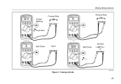
...REL AutoHOLD Hz % mV V LO V OFF mA A A A mA A COM V 10A MAX FUSED 400mA FUSED Typical Reading Forward Bias + Single Beep 87 V TRUE RMS MULTIMETER MIN MAX Peak MIN MAX ˚C/˚... RANGE REL AutoHOLD Hz % mV V LO V OFF mA A A A mA A COM V 10A MAX FUSED 400mA FUSED Making Measurements Reverse Bias + 87 V TRUE RMS MULTIMETER MIN MAX Peak MIN MAX ˚C/˚F RANGE REL... AutoHOLD Hz % mV V LO V OFF mA A A A mA A COM V 10A MAX FUSED 400mA FUSED Bad Diode Open 87 V TRUE RMS MULTIMETER MIN MAX Peak MIN MAX ˚C/˚F RANGE REL AutoHOLD Hz ...
...REL AutoHOLD Hz % mV V LO V OFF mA A A A mA A COM V 10A MAX FUSED 400mA FUSED Typical Reading Forward Bias + Single Beep 87 V TRUE RMS MULTIMETER MIN MAX Peak MIN MAX ˚C/˚... RANGE REL AutoHOLD Hz % mV V LO V OFF mA A A A mA A COM V 10A MAX FUSED 400mA FUSED Making Measurements Reverse Bias + 87 V TRUE RMS MULTIMETER MIN MAX Peak MIN MAX ˚C/˚F RANGE REL... AutoHOLD Hz % mV V LO V OFF mA A A A mA A COM V 10A MAX FUSED 400mA FUSED Bad Diode Open 87 V TRUE RMS MULTIMETER MIN MAX Peak MIN MAX ˚C/˚F RANGE REL AutoHOLD Hz ...

FE 83V & 87V Users Manual
Page 32
.... Insert the black lead into the A terminal. Note To avoid blowing the Meter's 400 mA fuse, use the mA/µA terminal only if you must break the circuit under test: • Check the Meter's fuses before measuring current. • Use the proper terminals, function, and range for 18 hours or less....0 mA, 6000 mA, and 10 A. To measure current, refer to earth is displayed as follows: 1. Turn off power to the equipment under test, then place the Meter in parallel with the circuit. WCaution To avoid possible damage to the Meter or to the circuit. AC current is greater...
.... Insert the black lead into the A terminal. Note To avoid blowing the Meter's 400 mA fuse, use the mA/µA terminal only if you must break the circuit under test: • Check the Meter's fuses before measuring current. • Use the proper terminals, function, and range for 18 hours or less....0 mA, 6000 mA, and 10 A. To measure current, refer to earth is displayed as follows: 1. Turn off power to the equipment under test, then place the Meter in parallel with the circuit. WCaution To avoid possible damage to the Meter or to the circuit. AC current is greater...

FE 83V & 87V Users Manual
Page 34
...6000 µA (6 mA), or mA/A for currents above 6000 µA. 4. If you are using the A terminal, set up correctly, test the Meter's fuses as described under "Testing the Fuses". • A current Meter drops a small voltage across itself, which might affect circuit operation. Turn off power to be... tested. You can calculate this burden voltage using the mA/µA terminal, set the rotary switch to mA/A. ...
...6000 µA (6 mA), or mA/A for currents above 6000 µA. 4. If you are using the A terminal, set up correctly, test the Meter's fuses as described under "Testing the Fuses". • A current Meter drops a small voltage across itself, which might affect circuit operation. Turn off power to be... tested. You can calculate this burden voltage using the mA/µA terminal, set the rotary switch to mA/A. ...

FE 83V & 87V Users Manual
Page 43
...in the terminals. 3. If the Meter does not chirp or flash "LEAd", the fuse is turned to Table 8 for the appropriate replacement fuse. XWWarning To avoid electrical shock or personal injury, remove the test leads and any dirt that current terminal is good. Refer to a non-current function,...cleaning and oiling agent (such as shown in Figure 10. Clean the terminals as described in the 80 Series V Service Information. Maintenance Fuse Test If a test lead is plugged into the mA/µA or A terminal and the rotary switch is bad and must be replaced. Maintenance XWWarning To ...
...in the terminals. 3. If the Meter does not chirp or flash "LEAd", the fuse is turned to Table 8 for the appropriate replacement fuse. XWWarning To avoid electrical shock or personal injury, remove the test leads and any dirt that current terminal is good. Refer to a non-current function,...cleaning and oiling agent (such as shown in Figure 10. Clean the terminals as described in the 80 Series V Service Information. Maintenance Fuse Test If a test lead is plugged into the mA/µA or A terminal and the rotary switch is bad and must be replaced. Maintenance XWWarning To ...
FE 83V & 87V Users Manual
Page 44
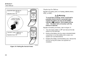
... RANGE REL mV V AutoHOLD Hz % mA A V LO A OFF A mA A COM V 10A MAX FUSED 400mA FUSED Good F1 fuse: 0.995 kΩ to OFF and remove the test leads from the terminals. 2. Testing the Current Fuses Replacing the Battery Replace the battery with a 9 V battery (NEDA A1604, 6F22, or 006P). Turn the... rotary switch to 1.005 kΩ Replace fuse: OL 87 V TRUE RMS MULTIMETER MIN MAX Peak MIN ...
... RANGE REL mV V AutoHOLD Hz % mA A V LO A OFF A mA A COM V 10A MAX FUSED 400mA FUSED Good F1 fuse: 0.995 kΩ to OFF and remove the test leads from the terminals. 2. Testing the Current Fuses Replacing the Battery Replace the battery with a 9 V battery (NEDA A1604, 6F22, or 006P). Turn the... rotary switch to 1.005 kΩ Replace fuse: OL 87 V TRUE RMS MULTIMETER MIN MAX Peak MIN ...

FE 83V & 87V Users Manual
Page 45
...screwdriver to separate the two halves of the top case from the terminals. 2. Turn the rotary switch to OFF and remove the test leads from inside of the battery compartment to turn the battery door screws onequarter turn clockwise. Replace the case top, ensuring that the... follows: 1. Service and Parts If the Meter fails, check the battery and fuses. Replacing the Fuses Referring to "Contacting Fluke". 37 Remove the fuse by turning the screws one end loose, then sliding the fuse out of the Meter. Secure the door by gently prying one -quarter turn counterclockwise. 3. ...
...screwdriver to separate the two halves of the top case from the terminals. 2. Turn the rotary switch to OFF and remove the test leads from inside of the battery compartment to turn the battery door screws onequarter turn clockwise. Replace the case top, ensuring that the... follows: 1. Service and Parts If the Meter fails, check the battery and fuses. Replacing the Fuses Referring to "Contacting Fluke". 37 Remove the fuse by turning the screws one end loose, then sliding the fuse out of the Meter. Secure the door by gently prying one -quarter turn counterclockwise. 3. ...

Getting Started Guide
Page 3
Table of Contents Title Page Introduction...1 Contacting Fluke ...1 Safety Information ...1 The Meter's Features ...4 Power-Up Options ...11 Automatic Power-Off 11 Input Alert™ Feature 11 Low Pass Filter (87 11 Bar Graph...12 AutoHOLD ® Mode ...13 Relative Mode ...13 Maintenance...13 General Maintenance 13 Fuse Test ...13 Specifications ...14 Detailed Specifications 15 i
Table of Contents Title Page Introduction...1 Contacting Fluke ...1 Safety Information ...1 The Meter's Features ...4 Power-Up Options ...11 Automatic Power-Off 11 Input Alert™ Feature 11 Low Pass Filter (87 11 Bar Graph...12 AutoHOLD ® Mode ...13 Relative Mode ...13 Maintenance...13 General Maintenance 13 Fuse Test ...13 Specifications ...14 Detailed Specifications 15 i

Getting Started Guide
Page 8
... by the manual. • Use the proper terminals, function, and range for all measurements. • Before measuring current, check the Meter's fuses. (See "Fuse Test" in the Meter case, to verify the presence of hazardous voltage. Remember to detect the possible presence of hazardous voltages. First, make a voltage measurement without ...
... by the manual. • Use the proper terminals, function, and range for all measurements. • Before measuring current, check the Meter's fuses. (See "Fuse Test" in the Meter case, to verify the presence of hazardous voltage. Remember to detect the possible presence of hazardous voltages. First, make a voltage measurement without ...

Getting Started Guide
Page 9
... designed to protect against transients in equipment in large buildings. See Manual. $ Conforms to European Union directives. Important information. T Double insulated R Continuity test or continuity beeper tone. G Diode s Inspected and licensed by TÜV Product Services. 3 W Risk of Danger. Low battery when displayed. E.... M Battery. Multimeters Safety Information B AC (Alternating Current) Table 1. Electrical Symbols J Earth ground F DC (Direct Current) I Fuse X Hazardous voltage P Conforms to relevant Canadian Standards Association directives.
... designed to protect against transients in equipment in large buildings. See Manual. $ Conforms to European Union directives. Important information. T Double insulated R Continuity test or continuity beeper tone. G Diode s Inspected and licensed by TÜV Product Services. 3 W Risk of Danger. Low battery when displayed. E.... M Battery. Multimeters Safety Information B AC (Alternating Current) Table 1. Electrical Symbols J Earth ground F DC (Direct Current) I Fuse X Hazardous voltage P Conforms to relevant Canadian Standards Association directives.

Getting Started Guide
Page 17
...to verify the presence of hazardous voltage. If MIN MAX Recording is enabled, the Meter will not power off if you are testing and blow the Meter's fuse. W Caution Placing the probes across (in parallel with reduced accuracy to the measurement below 1 kHz. The Meter continues measuring ...voltage measurement without the filter to the correct current position, the beeper warns you from attempting to Table 4. Input Alert™ Feature If a test lead is intended to stop you by pressing the RANGE button. This warning is plugged into a current terminal. The low pass filter can ...
...to verify the presence of hazardous voltage. If MIN MAX Recording is enabled, the Meter will not power off if you are testing and blow the Meter's fuse. W Caution Placing the probes across (in parallel with reduced accuracy to the measurement below 1 kHz. The Meter continues measuring ...voltage measurement without the filter to the correct current position, the beeper warns you from attempting to Table 4. Input Alert™ Feature If a test lead is intended to stop you by pressing the RANGE button. This warning is plugged into a current terminal. The low pass filter can ...

Getting Started Guide
Page 19
... wipe the case with the amperage, voltage, and speed ratings shown in Replacement Parts in the Users Manual located on the display. Fuse Test If a test lead is turned to zero the display and store the present reading as described in this mode. XWWarning To avoid electrical shock or ...personal injury, remove the test leads and any input signals before replacing the battery or fuses. The AutoHOLD mode captures the present reading on the 80 Series V User Manual CD. 13 The Meter is...
... wipe the case with the amperage, voltage, and speed ratings shown in Replacement Parts in the Users Manual located on the display. Fuse Test If a test lead is turned to zero the display and store the present reading as described in this mode. XWWarning To avoid electrical shock or ...personal injury, remove the test leads and any input signals before replacing the battery or fuses. The AutoHOLD mode captures the present reading on the 80 Series V User Manual CD. 13 The Meter is...


