
FE 83V & 87V Users Manual
Page 2
... AS FITNESS FOR A PARTICULAR PURPOSE, ARE EXPRESSED OR IMPLIED. Fluke Corporation Fluke Europe B.V. This warranty covers the original purchaser only and is defective, contact your product on then current component acquisition costs. If the product is not transferable. This warranty does not cover fuses, disposable batteries, damage from the date of purchase, this...
... AS FITNESS FOR A PARTICULAR PURPOSE, ARE EXPRESSED OR IMPLIED. Fluke Corporation Fluke Europe B.V. This warranty covers the original purchaser only and is defective, contact your product on then current component acquisition costs. If the product is not transferable. This warranty does not cover fuses, disposable batteries, damage from the date of purchase, this...

FE 83V & 87V Users Manual
Page 4
80 Series V Users Manual Measuring AC or DC Current 24 Measuring Frequency 27 Measuring Duty Cycle 29 Determining Pulse Width 30 Bar Graph...30 Zoom Mode (Power Up Option Only 31 Uses for the Zoom Mode 31 HiRes Mode (Model 87) ...31 MIN MAX Recording Mode 32 Smooth Feature (Power Up Option Only 32 AutoHOLD Mode...34 Relative Mode ...34 Maintenance...35 General Maintenance...35 Fuse Test ...35 Replacing the Battery...36 Replacing the Fuses ...37 Service and Parts...37 Specifications ...43 Detailed Specifications 44 ii
80 Series V Users Manual Measuring AC or DC Current 24 Measuring Frequency 27 Measuring Duty Cycle 29 Determining Pulse Width 30 Bar Graph...30 Zoom Mode (Power Up Option Only 31 Uses for the Zoom Mode 31 HiRes Mode (Model 87) ...31 MIN MAX Recording Mode 32 Smooth Feature (Power Up Option Only 32 AutoHOLD Mode...34 Relative Mode ...34 Maintenance...35 General Maintenance...35 Fuse Test ...35 Replacing the Battery...36 Replacing the Fuses ...37 Service and Parts...37 Specifications ...43 Detailed Specifications 44 ii

FE 83V & 87V Users Manual
Page 7
Measuring AC and DC Voltage 14 3. Measuring Resistance ...19 6. Components of Figures Figure Title Page 1. Display Features (Model 87) ...11 2. Testing a Diode...23 8. Testing the Current Fuses ...36 11. Battery and Fuse Replacement 38 12. Testing for Continuity...17 5. Measuring Current...25 9. Replaceable Parts ...41 v Low Pass Filter ...15 4. Measuring Capacitance...21 7. List of Duty Cycle Measurements 29 10.
Measuring AC and DC Voltage 14 3. Measuring Resistance ...19 6. Components of Figures Figure Title Page 1. Display Features (Model 87) ...11 2. Testing a Diode...23 8. Testing the Current Fuses ...36 11. Battery and Fuse Replacement 38 12. Testing for Continuity...17 5. Measuring Current...25 9. Replaceable Parts ...41 v Low Pass Filter ...15 4. Measuring Capacitance...21 7. List of Duty Cycle Measurements 29 10.

FE 83V & 87V Users Manual
Page 11
...; Do not use the Low Pass Filter option to verify the presence of hazardous voltage. These voltages pose a shock hazard. • Use only the replacement fuses specified by the manual. • Use the proper terminals, function, and range for measurements. • Avoid working with the circuit. Then select the filter function...
...; Do not use the Low Pass Filter option to verify the presence of hazardous voltage. These voltages pose a shock hazard. • Use only the replacement fuses specified by the manual. • Use the proper terminals, function, and range for measurements. • Avoid working with the circuit. Then select the filter function...

FE 83V & 87V Users Manual
Page 12
80 Series V Users Manual WCaution To avoid possible damage to the Meter or to the equipment under test, follow these guidelines: • Disconnect circuit power and discharge all high-voltage capacitors before testing resistance, continuity, diodes, or capacitance. • Use the proper terminals, function, and range for all measurements. • Before measuring current, check the Meter's fuses. (See "Fuse Test".) 4
80 Series V Users Manual WCaution To avoid possible damage to the Meter or to the equipment under test, follow these guidelines: • Disconnect circuit power and discharge all high-voltage capacitors before testing resistance, continuity, diodes, or capacitance. • Use the proper terminals, function, and range for all measurements. • Before measuring current, check the Meter's fuses. (See "Fuse Test".) 4

FE 83V & 87V Users Manual
Page 13
... relevant Canadian Standards Association directives. G Diode s Inspected and licensed by TÜV Product Services. 5 Electrical Symbols B AC (Alternating Current) F DC (Direct Current) X Hazardous voltage J I P Earth ground Fuse Conforms to protect against transients from the primary supply level, such as distribution panels, feeders and short branch circuits, and lighting systems in fixedequipment installations...
... relevant Canadian Standards Association directives. G Diode s Inspected and licensed by TÜV Product Services. 5 Electrical Symbols B AC (Alternating Current) F DC (Direct Current) X Hazardous voltage J I P Earth ground Fuse Conforms to protect against transients from the primary supply level, such as distribution panels, feeders and short branch circuits, and lighting systems in fixedequipment installations...

FE 83V & 87V Users Manual
Page 21
... you do not turn the rotary switch to measure voltage, continuity, resistance, capacitance, or diode values when the leads are testing and blow the Meter's fuse. Making Measurements The following sections describe how to take measurements with ) a powered circuit when a lead is plugged into the mA/µA or A terminal, but the...
... you do not turn the rotary switch to measure voltage, continuity, resistance, capacitance, or diode values when the leads are testing and blow the Meter's fuse. Making Measurements The following sections describe how to take measurements with ) a powered circuit when a lead is plugged into the mA/µA or A terminal, but the...

FE 83V & 87V Users Manual
Page 22
... AC Voltage V MIN MAX Peak MIN MAX 4½ DIGITS 1 Second ˚C/˚F RANGE REL mV V AutoHOLD Hz % mA A LO V A OFF A mA A COM V 10A MAX FUSED 400mA FUSED Switch Box 87 V TRUE RMS MULTIMETER DC Voltage mV V MIN MAX Peak MIN MAX 4½ DIGITS 1 Second ˚C/˚F RANGE REL mV V AutoHOLD Hz % mA...
... AC Voltage V MIN MAX Peak MIN MAX 4½ DIGITS 1 Second ˚C/˚F RANGE REL mV V AutoHOLD Hz % mA A LO V A OFF A mA A COM V 10A MAX FUSED 400mA FUSED Switch Box 87 V TRUE RMS MULTIMETER DC Voltage mV V MIN MAX Peak MIN MAX 4½ DIGITS 1 Second ˚C/˚F RANGE REL mV V AutoHOLD Hz % mA...
FE 83V & 87V Users Manual
Page 25
Testing for Continuity aom4f.eps 17 For in-circuit tests, turn circuit power off. 87 V TRUE RMS MULTIMETER 4½ DIGITS 1 Second MIN MAX Peak MIN MAX ˚C/˚F RANGE REL mV V AutoHOLD Hz % mA A LO V A OFF A mA A COM V 10A MAX FUSED 400mA FUSED Activates continuity beeper ON (closed) 87 V TRUE RMS MULTIMETER MIN MAX Peak MIN MAX 4½ DIGITS 1 Second ˚C/˚F RANGE REL mV V AutoHOLD Hz % mA A LO V A OFF A mA A COM V 10A MAX FUSED 400mA FUSED Making Measurements OFF (open) Figure 4.
Testing for Continuity aom4f.eps 17 For in-circuit tests, turn circuit power off. 87 V TRUE RMS MULTIMETER 4½ DIGITS 1 Second MIN MAX Peak MIN MAX ˚C/˚F RANGE REL mV V AutoHOLD Hz % mA A LO V A OFF A mA A COM V 10A MAX FUSED 400mA FUSED Activates continuity beeper ON (closed) 87 V TRUE RMS MULTIMETER MIN MAX Peak MIN MAX 4½ DIGITS 1 Second ˚C/˚F RANGE REL mV V AutoHOLD Hz % mA A LO V A OFF A mA A COM V 10A MAX FUSED 400mA FUSED Making Measurements OFF (open) Figure 4.

FE 83V & 87V Users Manual
Page 27
Measuring Resistance Disconnect aom6f.eps 19 In-Circuit Resistance Measurements 87 V TRUE RMS MULTIMETER Circuit Power OFF MIN MAX Peak MIN MAX 4½ DIGITS 1 Second ˚C/˚F RANGE REL mV V AutoHOLD Hz % mA A LO V A OFF A mA A COM V 10A MAX FUSED 400mA FUSED Making Measurements Isolating a Potentiometer 1 3 2 Disconnect 1 2 3 Isolating a Resistor Figure 5.
Measuring Resistance Disconnect aom6f.eps 19 In-Circuit Resistance Measurements 87 V TRUE RMS MULTIMETER Circuit Power OFF MIN MAX Peak MIN MAX 4½ DIGITS 1 Second ˚C/˚F RANGE REL mV V AutoHOLD Hz % mA A LO V A OFF A mA A COM V 10A MAX FUSED 400mA FUSED Making Measurements Isolating a Potentiometer 1 3 2 Disconnect 1 2 3 Isolating a Resistor Figure 5.

FE 83V & 87V Users Manual
Page 29
... RMS MULTIMETER MIN MAX Peak MIN MAX 4½ DIGITS 1 Second ˚C/˚F RANGE REL mV V AutoHOLD Hz % mA A LO V A OFF A mA A COM V 10A MAX FUSED 400mA FUSED + Figure 6. Measuring Capacitance aom10f.eps 21 To improve the accuracy of measurements less than 1000 nF, use the relative (REL) mode to the equipment under...
... RMS MULTIMETER MIN MAX Peak MIN MAX 4½ DIGITS 1 Second ˚C/˚F RANGE REL mV V AutoHOLD Hz % mA A LO V A OFF A mA A COM V 10A MAX FUSED 400mA FUSED + Figure 6. Measuring Capacitance aom10f.eps 21 To improve the accuracy of measurements less than 1000 nF, use the relative (REL) mode to the equipment under...
FE 83V & 87V Users Manual
Page 31
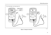
...V TRUE RMS MULTIMETER MIN MAX Peak MIN MAX ˚C/˚F RANGE REL AutoHOLD Hz % mV V LO V OFF mA A A A mA A COM V 10A MAX FUSED 400mA FUSED Making Measurements Reverse Bias + 87 V TRUE RMS MULTIMETER MIN MAX Peak MIN MAX ˚C/˚F RANGE REL AutoHOLD Hz % mV V LO V OFF mA A A A... mA A COM V 10A MAX FUSED 400mA FUSED Bad Diode Open 87 V TRUE RMS MULTIMETER MIN MAX Peak MIN MAX ˚C/˚F RANGE REL AutoHOLD Hz % mV V LO V OFF mA A A A mA A ...
...V TRUE RMS MULTIMETER MIN MAX Peak MIN MAX ˚C/˚F RANGE REL AutoHOLD Hz % mV V LO V OFF mA A A A mA A COM V 10A MAX FUSED 400mA FUSED Making Measurements Reverse Bias + 87 V TRUE RMS MULTIMETER MIN MAX Peak MIN MAX ˚C/˚F RANGE REL AutoHOLD Hz % mV V LO V OFF mA A A A... mA A COM V 10A MAX FUSED 400mA FUSED Bad Diode Open 87 V TRUE RMS MULTIMETER MIN MAX Peak MIN MAX ˚C/˚F RANGE REL AutoHOLD Hz % mV V LO V OFF mA A A A mA A ...

FE 83V & 87V Users Manual
Page 32
....00 mA, 400.0 mA, 6000 mA, and 10 A. Note To avoid blowing the Meter's 400 mA fuse, use the mA/µA terminal only if you must break the circuit under test: • Check the Meter's fuses before measuring current. • Use the proper terminals, function, and range for 18 hours or less.... 24 You may damage the Meter or be injured if the fuse blows during such a measurement. For currents between 6 mA and 400 mA, insert the red lead into the mA/µA terminal. AC current is less than...
....00 mA, 400.0 mA, 6000 mA, and 10 A. Note To avoid blowing the Meter's 400 mA fuse, use the mA/µA terminal only if you must break the circuit under test: • Check the Meter's fuses before measuring current. • Use the proper terminals, function, and range for 18 hours or less.... 24 You may damage the Meter or be injured if the fuse blows during such a measurement. For currents between 6 mA and 400 mA, insert the red lead into the mA/µA terminal. AC current is less than...

FE 83V & 87V Users Manual
Page 33
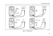
Making Measurements Total current to disconnect meter. Measuring Current 5 aom7f.eps 25 OFF to circuit 5 Current through one component Figure 8. ON for measurement. 1 87 V TRUE RMS MULTIMETER MIN MAX Peak MIN MAX 4½ DIGITS 1 Second ˚C/˚F RANGE REL mV V AutoHOLD Hz % mA A LO V A OFF A mA A COM V 10A MAX FUSED 400mA FUSED 4 mA A 3 A 2 Circuit Power: OFF to connect meter.
Making Measurements Total current to disconnect meter. Measuring Current 5 aom7f.eps 25 OFF to circuit 5 Current through one component Figure 8. ON for measurement. 1 87 V TRUE RMS MULTIMETER MIN MAX Peak MIN MAX 4½ DIGITS 1 Second ˚C/˚F RANGE REL mV V AutoHOLD Hz % mA A LO V A OFF A mA A COM V 10A MAX FUSED 400mA FUSED 4 mA A 3 A 2 Circuit Power: OFF to connect meter.

FE 83V & 87V Users Manual
Page 34
... to mA/A. Turn off power to normal operation. You can calculate this burden voltage using the A terminal, set up correctly, test the Meter's fuses as described under "Testing the Fuses". • A current Meter drops a small voltage across itself, which might affect circuit operation. Reversing the leads will produce a negative reading, but will...
... to mA/A. Turn off power to normal operation. You can calculate this burden voltage using the A terminal, set up correctly, test the Meter's fuses as described under "Testing the Fuses". • A current Meter drops a small voltage across itself, which might affect circuit operation. Reversing the leads will produce a negative reading, but will...

FE 83V & 87V Users Manual
Page 43
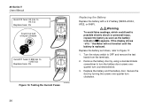
...not use abrasives or solvents. Clean the terminals as follows: 1. Refer to a non-current function, the Meter chirps and flashes "LEAd" if the fuse associated with the amperage, voltage, and speed ratings shown in the terminals can affect readings and can falsely activate the Input Alert feature. To test... a new swab with a damp cloth and mild detergent. If the tests give readings other than those shown, have the Meter serviced. Maintenance Fuse Test If a test lead is plugged into the mA/µA or A terminal and the rotary switch is turned to Table 8 for the appropriate replacement...
...not use abrasives or solvents. Clean the terminals as follows: 1. Refer to a non-current function, the Meter chirps and flashes "LEAd" if the fuse associated with the amperage, voltage, and speed ratings shown in the terminals can affect readings and can falsely activate the Input Alert feature. To test... a new swab with a damp cloth and mild detergent. If the tests give readings other than those shown, have the Meter serviced. Maintenance Fuse Test If a test lead is plugged into the mA/µA or A terminal and the rotary switch is turned to Table 8 for the appropriate replacement...
FE 83V & 87V Users Manual
Page 44
... 4½ DIGITS 1 Second ˚C/˚F RANGE REL mV V AutoHOLD Hz % mA A V LO A OFF A mA A COM V 10A MAX FUSED 400mA FUSED Good F1 fuse: 0.995 kΩ to OFF and remove the test leads from the terminals. 2. Secure the door by using a standard-blade screwdriver to turn the battery... door screws onequarter turn clockwise. 36 Turn the rotary switch to 1.005 kΩ Replace fuse: OL 87 V TRUE RMS MULTIMETER MIN MAX Peak MIN MAX 4½ DIGITS 1 Second ˚C/˚F RANGE REL mV V AutoHOLD Hz % mA A V ...
... 4½ DIGITS 1 Second ˚C/˚F RANGE REL mV V AutoHOLD Hz % mA A V LO A OFF A mA A COM V 10A MAX FUSED 400mA FUSED Good F1 fuse: 0.995 kΩ to OFF and remove the test leads from the terminals. 2. Secure the door by using a standard-blade screwdriver to turn the battery... door screws onequarter turn clockwise. 36 Turn the rotary switch to 1.005 kΩ Replace fuse: OL 87 V TRUE RMS MULTIMETER MIN MAX Peak MIN MAX 4½ DIGITS 1 Second ˚C/˚F RANGE REL mV V AutoHOLD Hz % mA A V ...

FE 83V & 87V Users Manual
Page 45
.... 3. Remove the three Phillips-head screws from inside of the battery compartment to Figure 11, examine or replace the Meter's fuses as follows: 1. Remove the fuse by gently prying one -quarter turn the case over. 4. Secure the door by using a standard-blade screwdriver to OFF and...the top case from the case bottom and turn clockwise. Replacing the Fuses Referring to separate the two halves of the case. 5. Replacement parts and accessories are in Table 8. Review this manual to "Contacting Fluke". 37 Replace the case top, ensuring that the rotary switch and the...
.... 3. Remove the three Phillips-head screws from inside of the battery compartment to Figure 11, examine or replace the Meter's fuses as follows: 1. Remove the fuse by gently prying one -quarter turn the case over. 4. Secure the door by using a standard-blade screwdriver to OFF and...the top case from the case bottom and turn clockwise. Replacing the Fuses Referring to separate the two halves of the case. 5. Replacement parts and accessories are in Table 8. Review this manual to "Contacting Fluke". 37 Replace the case top, ensuring that the rotary switch and the...

FE 83V & 87V Users Manual
Page 46
80 Series V Users Manual F1 F2 1 Figure 11. Battery and Fuse Replacement aom12f.eps 38
80 Series V Users Manual F1 F2 1 Figure 11. Battery and Fuse Replacement aom12f.eps 38

FE 83V & 87V Users Manual
Page 47
Table 8. Replacement Parts Item Description BT1 Battery, 9 V BT2 Cable Assy, 9 V Battery Snap F1 W Fuse, 0.440 A, 1000 V, FAST F2 W Fuse, 11 A, 1000 V, FAST H2-4 Screw, Case H5-9 Screw, Bottom Shield J1-2 Elastomeric Connector MP2 Shield, Top MP4...(PAD XFER) MP41 Housing, RSOB WTo ensure safety, use exact replacement only. Service and Parts Qty. 1 1 1 1 3 5 2 1 1 1 1 1 1 2 1 1 1 1 4 1 1 Fluke Part or Model Number 2139179 2064217 943121 803293 832246 448456 817460 2073906 2074025 2073992 2073871 2100482 822643 824466 828541 831933 2074033 2073938 1567683 2073950 2073945...
Table 8. Replacement Parts Item Description BT1 Battery, 9 V BT2 Cable Assy, 9 V Battery Snap F1 W Fuse, 0.440 A, 1000 V, FAST F2 W Fuse, 11 A, 1000 V, FAST H2-4 Screw, Case H5-9 Screw, Bottom Shield J1-2 Elastomeric Connector MP2 Shield, Top MP4...(PAD XFER) MP41 Housing, RSOB WTo ensure safety, use exact replacement only. Service and Parts Qty. 1 1 1 1 3 5 2 1 1 1 1 1 1 2 1 1 1 1 4 1 1 Fluke Part or Model Number 2139179 2064217 943121 803293 832246 448456 817460 2073906 2074025 2073992 2073871 2100482 822643 824466 828541 831933 2074033 2073938 1567683 2073950 2073945...


