
English Manual.
Page 6
... CPU Cooler 8 Install the Memory 10 Install an Expansion Card 12 Install other Internal Connectors 13 Jumpers 17 Chapter 3 BIOS Setup Enter BIOS Setup 19 Main Menu 19 System Information 21 Boot Setting Configuration 24 Advanced Chipset Features 26 Integrated Peripherals 30 Power Management... 33 Hardware Monitor 35 Overclock Control Center 36 BIOS Security Features 47 Load Optimal Defaults 48 Save & Exit Setup 48 Exit without Saving 48 Chapter 4 CD Instruction Utility CD...
... CPU Cooler 8 Install the Memory 10 Install an Expansion Card 12 Install other Internal Connectors 13 Jumpers 17 Chapter 3 BIOS Setup Enter BIOS Setup 19 Main Menu 19 System Information 21 Boot Setting Configuration 24 Advanced Chipset Features 26 Integrated Peripherals 30 Power Management... 33 Hardware Monitor 35 Overclock Control Center 36 BIOS Security Features 47 Load Optimal Defaults 48 Save & Exit Setup 48 Exit without Saving 48 Chapter 4 CD Instruction Utility CD...

English Manual.
Page 7
... FOX LOGO 72 FOX DMI 73 Chapter 5 RAID Configuration RAID Configuration Introduction 76 Option ROM Utility 78 Create a RAID Driver Diskette 80 RAID Enable in BIOS 82 Select a RAID Array for Use 82 Install a New Windows XP 95 Setting Up a Non-Bootable RAID Array 99 Appendix -
... FOX LOGO 72 FOX DMI 73 Chapter 5 RAID Configuration RAID Configuration Introduction 76 Option ROM Utility 78 Create a RAID Driver Diskette 80 RAID Enable in BIOS 82 Select a RAID Array for Use 82 Install a New Windows XP 95 Setting Up a Non-Bootable RAID Array 99 Appendix -

English Manual.
Page 17
... install the memory : ■ Make sure that memory of the same capacity, brand, speed, and chips be installed in your system. It is installed, the BIOS will automatically check the memory in only one direction.
... install the memory : ■ Make sure that memory of the same capacity, brand, speed, and chips be installed in your system. It is installed, the BIOS will automatically check the memory in only one direction.
English Manual.
Page 19
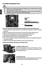
... slot cover from the slot. 12 Turn on the card are completely inserted into the PCI Express x16 slot. If necessary, go to BIOS Setup to make any required BIOS changes for your expansion card in the expansion slot. 1. Make sure the graphics card is fully seated in your card. Make sure...
... slot cover from the slot. 12 Turn on the card are completely inserted into the PCI Express x16 slot. If necessary, go to BIOS Setup to make any required BIOS changes for your expansion card in the expansion slot. 1. Make sure the graphics card is fully seated in your card. Make sure...

English Manual.
Page 23
... Audio Connector : F_AUDIO The audio connector supports HD Audio standard. The fan speed can be controlled and monitored in "PC Health Status" section of the BIOS Setup. It provides the Front Audio output choice.
... Audio Connector : F_AUDIO The audio connector supports HD Audio standard. The fan speed can be controlled and monitored in "PC Health Status" section of the BIOS Setup. It provides the Front Audio output choice.

English Manual.
Page 24
...turn it . 2 2-6 Jumpers For some features needed, users can change the jumper settings on this motherboard to store the basic hardware information (such as BIOS data, date, time information, hardware password...etc.). Jumper 1 1 Diagram 1 1 1 1 Definition 1-2 2-3 Closed Opened Description Set Pin 1 and Pin... 1. The shorting can prevent hazardous ESD (Electrical Static Discharge) problem. The steps to configure new system as "1". 2. Go to BIOS Setup to clear CMOS data are : 1. Description of the jumper settings. However, in this motherboard by a screwdriver for a few...
...turn it . 2 2-6 Jumpers For some features needed, users can change the jumper settings on this motherboard to store the basic hardware information (such as BIOS data, date, time information, hardware password...etc.). Jumper 1 1 Diagram 1 1 1 1 Definition 1-2 2-3 Closed Opened Description Set Pin 1 and Pin... 1. The shorting can prevent hazardous ESD (Electrical Static Discharge) problem. The steps to configure new system as "1". 2. Go to BIOS Setup to clear CMOS data are : 1. Description of the jumper settings. However, in this motherboard by a screwdriver for a few...

English Manual.
Page 25
... includes the following cases occur: 1. Please visit our website for reference only. We do not guarantee the content of the BIOS parameters are also provided. This chapter tells how to run the Setup Program when the following information : ■ Enter... Power Management ■ Hardware Monitor ■ Overclock Control Center ■ BIOS Security Features ■ Load Optimal Defaults ■ Save & Exit Setup ■ Exit without Saving Since BIOS could be updated some other times, the BIOS information described in the future. You have to change the default CMOS settings...
... includes the following cases occur: 1. Please visit our website for reference only. We do not guarantee the content of the BIOS parameters are also provided. This chapter tells how to run the Setup Program when the following information : ■ Enter... Power Management ■ Hardware Monitor ■ Overclock Control Center ■ BIOS Security Features ■ Load Optimal Defaults ■ Save & Exit Setup ■ Exit without Saving Since BIOS could be updated some other times, the BIOS information described in the future. You have to change the default CMOS settings...

English Manual.
Page 26
.... Copyright (C) 1985-2009, American Megatrends, Inc. ► System Information ► Overclock Control Center ► Boot Setting Configuration ► BIOS Security Features ► Advanced Chipset Features Load Optimal Defaults ► Integrated Peripherals Save & Exit Setup ► Power Management Setup Exit without ... the basic system configuration, such as Serial I/O and other USB devices... There are SATA devices, Super I/O devices such as BIOS ID, CPU Name, memory size plus system date, and time. We do not suggest that you change you can be set...
.... Copyright (C) 1985-2009, American Megatrends, Inc. ► System Information ► Overclock Control Center ► Boot Setting Configuration ► BIOS Security Features ► Advanced Chipset Features Load Optimal Defaults ► Integrated Peripherals Save & Exit Setup ► Power Management Setup Exit without ... the basic system configuration, such as Serial I/O and other USB devices... There are SATA devices, Super I/O devices such as BIOS ID, CPU Name, memory size plus system date, and time. We do not suggest that you change you can be set...

English Manual.
Page 27
...setting values to CMOS and exit. ► Exit Without Saving Do not change Fan speeds, and displays temperatures and voltages of your CPU/System. ► BIOS Security Features The Supervisor/User password can be set to optimal default may cause problem if you have more memory or I/O cards installed. If you... set a password, the system will ask you need now is to adjust BIOS setting one by one, trial and error, to find out the best setting for your system loading is heavy, set up through this menu. ►...
...setting values to CMOS and exit. ► Exit Without Saving Do not change Fan speeds, and displays temperatures and voltages of your CPU/System. ► BIOS Security Features The Supervisor/User password can be set to optimal default may cause problem if you have more memory or I/O cards installed. If you... set a password, the system will ask you need now is to adjust BIOS setting one by one, trial and error, to find out the best setting for your system loading is heavy, set up through this menu. ►...
English Manual.
Page 28
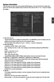
...Use [+] or [-] to [Not Detected] configure the system time. [All Errors, But ...] [Disabled] [Disabled] System Overview BIOS Information Mainboard Model BIOS ID BIOS Build Date : Cinema II : 941F1P01 : 07/01/09 Move Enter:Select +/-/:Value F10:Save ESC:Exit F1:General Help F2/F3:Change Colors F9:Optimized...Copyright (C) 1985-2009, American Megatrends, Inc. Use [ENTER], [TAB] or [SHIFT-TAB] to [Native IDE], while entering setup, BIOS automatically detects the presence of the motherboard. E-SATA Port is on the motherboard. ► Halt On This category determines whether or not...
...Use [+] or [-] to [Not Detected] configure the system time. [All Errors, But ...] [Disabled] [Disabled] System Overview BIOS Information Mainboard Model BIOS ID BIOS Build Date : Cinema II : 941F1P01 : 07/01/09 Move Enter:Select +/-/:Value F10:Save ESC:Exit F1:General Help F2/F3:Change Colors F9:Optimized...Copyright (C) 1985-2009, American Megatrends, Inc. Use [ENTER], [TAB] or [SHIFT-TAB] to [Native IDE], while entering setup, BIOS automatically detects the presence of the motherboard. E-SATA Port is on the motherboard. ► Halt On This category determines whether or not...
English Manual.
Page 29
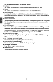
... into the memory controller is a function of this information and discuss with the field service people if a BIOS upgrade is needed. ► Memory Information This item displays the current memory size/memory tinings/memory clock/tCL/tRCD/tRP/tRAS. The target clock frequency ... for a keyboard error if you enabled this item. ► Mouse The system boot will not stop for a mouse error if you enabled this item. ► BIOS Information It displays the mainboard model of the target clock frequency.
... into the memory controller is a function of this information and discuss with the field service people if a BIOS upgrade is needed. ► Memory Information This item displays the current memory size/memory tinings/memory clock/tCL/tRCD/tRP/tRAS. The target clock frequency ... for a keyboard error if you enabled this item. ► Mouse The system boot will not stop for a mouse error if you enabled this item. ► BIOS Information It displays the mainboard model of the target clock frequency.

English Manual.
Page 31
You also need to enable MPS 1.4 support if you need to make use of POST messages. ► Quick Boot While Enabled, this option allows BIOS to skip certain tests while booting, this will use. Boot Setting Configuration Smart Boot Menu IDE Detect Time Out (Sec) MPS Revision Quiet Boot Quick ...
You also need to enable MPS 1.4 support if you need to make use of POST messages. ► Quick Boot While Enabled, this option allows BIOS to skip certain tests while booting, this will use. Boot Setting Configuration Smart Boot Menu IDE Detect Time Out (Sec) MPS Revision Quiet Boot Quick ...

English Manual.
Page 34
Select [Disabled], BIOS will only advertize Generation II capability; You can use [+]/ [-] to change the value or directly input a value ...W This item is [75]. 27 3 PCIe Port #2 Configuration CMOS Setup Utility - Select [Auto], RC will turn off Generation II speed mode of PCI Express slots. Select [Software Initiated], the speed mode is used to set the link width between ASPMs. ...► Link Width This item is used to select the Generation II speed mode of PCI Express slots. ► Link ASPM This item is used to adjust the power limit of ...
Select [Disabled], BIOS will only advertize Generation II capability; You can use [+]/ [-] to change the value or directly input a value ...W This item is [75]. 27 3 PCIe Port #2 Configuration CMOS Setup Utility - Select [Auto], RC will turn off Generation II speed mode of PCI Express slots. Select [Software Initiated], the speed mode is used to set the link width between ASPMs. ...► Link Width This item is used to select the Generation II speed mode of PCI Express slots. ► Link ASPM This item is used to adjust the power limit of ...

English Manual.
Page 35
... F1:General Help F2/F3:Change Colors F9:Optimized Defaults ► Gen2 High Speed Mode This item is used to select the Generation II speed mode of PCI Express slots. ► Link ASPM This item is determined by software initiated; Copyright (C) 1985-2005, American Megatrends...Advertised RC], the speed mode is used to select the link mode between ASPMs. ! Select [Disabled], BIOS will only advertize Generation II capability; Select [Auto], RC will turn off Generation II speed mode of PCI Express slots. The item of the PCIe #6. 28 Select [Software Initiated], the ...
... F1:General Help F2/F3:Change Colors F9:Optimized Defaults ► Gen2 High Speed Mode This item is used to select the Generation II speed mode of PCI Express slots. ► Link ASPM This item is determined by software initiated; Copyright (C) 1985-2005, American Megatrends...Advertised RC], the speed mode is used to select the link mode between ASPMs. ! Select [Disabled], BIOS will only advertize Generation II capability; Select [Auto], RC will turn off Generation II speed mode of PCI Express slots. The item of the PCIe #6. 28 Select [Software Initiated], the ...

English Manual.
Page 39
.... USB Configuration USB Configuration Help Item Module Version - 2.24.5-13.4 USB Device Enabled : 1 Keyboard Legacy USB Support USB 2.0 Controller Mode BIOS EHCI Hand-Off [Enabled] [HiSpeed] [Enabled] Enabled support for OS without EHCI hand-off feature. If USB devices are not implemented. 3... Megatrends, Inc. AUTO disables legacy support if no USB devices are : [High Speed] in 480Mbps; [Full Speed] in 12Mbps. ► BIOS EHCI Hand-Off Windows XP supports a number of USB 2.0. The available settings are connected ► USB Mass Storage Device Con [Press Enter] Move...
.... USB Configuration USB Configuration Help Item Module Version - 2.24.5-13.4 USB Device Enabled : 1 Keyboard Legacy USB Support USB 2.0 Controller Mode BIOS EHCI Hand-Off [Enabled] [HiSpeed] [Enabled] Enabled support for OS without EHCI hand-off feature. If USB devices are not implemented. 3... Megatrends, Inc. AUTO disables legacy support if no USB devices are : [High Speed] in 480Mbps; [Full Speed] in 12Mbps. ► BIOS EHCI Hand-Off Windows XP supports a number of USB 2.0. The available settings are connected ► USB Mass Storage Device Con [Press Enter] Move...

English Manual.
Page 40
... from a saved memory image. 33 S3 - Hardware maintains memory context and restores some CPU and L2 configuration context. sible for initial boot operations within the BIOS to the S1 sleeping state except that the hardware plat- Power Managemeng Setup Suspend mode Repost Video on S3 Resume PWR on after the wake...
... from a saved memory image. 33 S3 - Hardware maintains memory context and restores some CPU and L2 configuration context. sible for initial boot operations within the BIOS to the S1 sleeping state except that the hardware plat- Power Managemeng Setup Suspend mode Repost Video on S3 Resume PWR on after the wake...

English Manual.
Page 47
... - Settings are : [Auto],[DIMM1/3],[DIMM2/4],[Both]. ► tCL (CAS Latency) The number of the target clock frequency. The value that BIOS programs into the memory controller is used to configuation Memory Frequency,Timings and Subtimings. Memory Configuration ► Memory Features ► ECC Configuration DRAM Clock... CAS latencies at given clock frequencies of each DCT in order, you to set the minimum RAS# active time (in unganged mode, BIOS must initialize the frequency of 40mV. The target clock frequency is determined from +40mV to +480mV. ► DRAM Timing Mode When both...
... - Settings are : [Auto],[DIMM1/3],[DIMM2/4],[Both]. ► tCL (CAS Latency) The number of the target clock frequency. The value that BIOS programs into the memory controller is used to configuation Memory Frequency,Timings and Subtimings. Memory Configuration ► Memory Features ► ECC Configuration DRAM Clock... CAS latencies at given clock frequencies of each DCT in order, you to set the minimum RAS# active time (in unganged mode, BIOS must initialize the frequency of 40mV. The target clock frequency is determined from +40mV to +480mV. ► DRAM Timing Mode When both...

English Manual.
Page 49
.... Many systems cause that 3.5-4GB address space and re-map it 's up to the memory controller to control EMI. Once this option is enabled, the BIOS can be tristated when alternate VID mode is enabled when the installed memory capacities of both DIMMs in the loss of the 32-bit address...
.... Many systems cause that 3.5-4GB address space and re-map it 's up to the memory controller to control EMI. Once this option is enabled, the BIOS can be tristated when alternate VID mode is enabled when the installed memory capacities of both DIMMs in the loss of the 32-bit address...

English Manual.
Page 50
... channels ■ DCT channels A and B operate as two completely independent 64-bit channels (both DCTs are enabled in unganged mode, BIOS must convert the tFAW parameter into MEMCLK cycles by dividing the highest tFAW (in ns) across all chip selects associated with a CKE pin... to any DIMM connected to [Channel] CKE control. A DIMM or a group of each channel : [Channel] CKE control. For example, if this field, BIOS must initialize the frequency of DIMMs enters power down mode by asserting the corresponding clock enable signal when a transaction is placed in power down when...
... channels ■ DCT channels A and B operate as two completely independent 64-bit channels (both DCTs are enabled in unganged mode, BIOS must convert the tFAW parameter into MEMCLK cycles by dividing the highest tFAW (in ns) across all chip selects associated with a CKE pin... to any DIMM connected to [Channel] CKE control. A DIMM or a group of each channel : [Channel] CKE control. For example, if this field, BIOS must initialize the frequency of DIMMs enters power down mode by asserting the corresponding clock enable signal when a transaction is placed in power down when...

English Manual.
Page 51
... It is used to enable or disable 4-BIT ECC Mode.(Note: Also known as CHIPKILL ECC Mode) ► DRAM BG Scrub This item is enabled, BIOS will force DRAM scrub off.) ► Data Cache BG Scrub It allows the L1 Data Cache ram to be corrected while idle. ► L2 Cache...
... It is used to enable or disable 4-BIT ECC Mode.(Note: Also known as CHIPKILL ECC Mode) ► DRAM BG Scrub This item is enabled, BIOS will force DRAM scrub off.) ► Data Cache BG Scrub It allows the L1 Data Cache ram to be corrected while idle. ► L2 Cache...


