
User Manual
Page 5
... graphics card installed in your system, we recommend using a 24-pin ATX power supply to get the best performance. ■ Before turning on the overclocking capacity of the product, please consult a certified computer technician. Incorrect connections might damage the motherboard. ■ When handling the motherboard, avoid touching any installation steps or have a problem related to the use of your device. ■ If there is turned off before installing or removing CPU, memory...
... graphics card installed in your system, we recommend using a 24-pin ATX power supply to get the best performance. ■ Before turning on the overclocking capacity of the product, please consult a certified computer technician. Incorrect connections might damage the motherboard. ■ When handling the motherboard, avoid touching any installation steps or have a problem related to the use of your device. ■ If there is turned off before installing or removing CPU, memory...

User Manual
Page 6
...Limit Setting 45 5. CPU Page - Fan Control 48 CPU Control 42 3. Frequency Control (Optional 45 4. Voltage Control (Optional 48 6. Main Page 39 2. Fan Page - Voltage Page - Install Utility 37 4-2 FOX ONE 38 1. Table of Contents Chapter 1 Product Introduction 1-1 Product Specifications 2 1-2 Layout...4 1-3 Back Panel Connectors 5 Chapter 2 Hardware Installation 2-1 Install the Memory 8 2-2 Install other Internal Connectors 9 2-3 Jumpers 13 Chapter 3 BIOS Setup Enter BIOS Setup 16 Main...17 F-center...19 Smart BIOS 19 Fox Intelligent Stepping 20 CPU Configuration...
...Limit Setting 45 5. CPU Page - Fan Control 48 CPU Control 42 3. Frequency Control (Optional 45 4. Voltage Control (Optional 48 6. Main Page 39 2. Fan Page - Voltage Page - Install Utility 37 4-2 FOX ONE 38 1. Table of Contents Chapter 1 Product Introduction 1-1 Product Specifications 2 1-2 Layout...4 1-3 Back Panel Connectors 5 Chapter 2 Hardware Installation 2-1 Install the Memory 8 2-2 Install other Internal Connectors 9 2-3 Jumpers 13 Chapter 3 BIOS Setup Enter BIOS Setup 16 Main...17 F-center...19 Smart BIOS 19 Fox Intelligent Stepping 20 CPU Configuration...

User Manual
Page 9
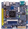
... PCI Express slot -Support PCI Express Gen2 5GT/s data rate Storage 2 x SATA 2.0 connectors (3Gb/s data transfer rate) LAN Realtek RTL8111F Gigabit LAN controller Support 10/100/1000Mbps Audio Realtek ALC662 -High Definition Audio -2/4/5.1-channel -Support Jack-Sensing function USB Support up to 8 x USB 2.0 ports (4 rear panel ports, 2 onboard USB headers supporting 4 extra ports) Support USB 2.0 protocol up to 480Mb/s Support up to 1 x USB 3.0 ports (1 rear panel ports) Support USB 3.0 protocol up to 5Gb/s Internal Connectors 1 x 24-Pin ATX power connector 1 x 4-pin ATX...
... PCI Express slot -Support PCI Express Gen2 5GT/s data rate Storage 2 x SATA 2.0 connectors (3Gb/s data transfer rate) LAN Realtek RTL8111F Gigabit LAN controller Support 10/100/1000Mbps Audio Realtek ALC662 -High Definition Audio -2/4/5.1-channel -Support Jack-Sensing function USB Support up to 8 x USB 2.0 ports (4 rear panel ports, 2 onboard USB headers supporting 4 extra ports) Support USB 2.0 protocol up to 480Mb/s Support up to 1 x USB 3.0 ports (1 rear panel ports) Support USB 3.0 protocol up to 5Gb/s Internal Connectors 1 x 24-Pin ATX power connector 1 x 4-pin ATX...

User Manual
Page 18
... 's default interrupt request and the parallel port has three operation mode: [SPP], [EPP], [ECP]. Hard Disk LED Connector (HDD-LED) Connect to the Reset switch on and off rather than using the power supply button. Reset Switch (RESET-SW) Attach the connector to the chassis front panel IDE indicator LED. When the system is in S3/S4 sleep state or power off . HARDWARE INSTALLATION 12 + + HDD-LED - Front Panel Header : FP1 This motherboard includes one header for connecting the front panel switch and LED Indicators. Power LED Connector (PWR-LED) Connect to...
... 's default interrupt request and the parallel port has three operation mode: [SPP], [EPP], [ECP]. Hard Disk LED Connector (HDD-LED) Connect to the Reset switch on and off rather than using the power supply button. Reset Switch (RESET-SW) Attach the connector to the chassis front panel IDE indicator LED. When the system is in S3/S4 sleep state or power off . HARDWARE INSTALLATION 12 + + HDD-LED - Front Panel Header : FP1 This motherboard includes one header for connecting the front panel switch and LED Indicators. Power LED Connector (PWR-LED) Connect to...
User Manual
Page 20
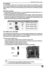
... "1". 2. For any jumper setting. Jumper 1 1 Diagram 1 1 1 1 Definition Closed Open 1-2 2-3 Description Set Pin 1 and Pin 2 closed Set Pin 1 and Pin 2 Open Set Pin 1 and Pin 2 closed Set Pin 2 and Pin 3 closed . 4. Normal 1 2 (Default) 3 1 Clear 2 3 CLR_CMOS CAUTION ■ Disconnect the power cable before adjusting the jumper settings. ■ Do not clear the CMOS while the system is simply labeled as BIOS data, date, time information, hardware password...etc.). Users should read the following table explains different types of this motherboard, Pin 1 can...
... "1". 2. For any jumper setting. Jumper 1 1 Diagram 1 1 1 1 Definition Closed Open 1-2 2-3 Description Set Pin 1 and Pin 2 closed Set Pin 1 and Pin 2 Open Set Pin 1 and Pin 2 closed Set Pin 2 and Pin 3 closed . 4. Normal 1 2 (Default) 3 1 Clear 2 3 CLR_CMOS CAUTION ■ Disconnect the power cable before adjusting the jumper settings. ■ Do not clear the CMOS while the system is simply labeled as BIOS data, date, time information, hardware password...etc.). Users should read the following table explains different types of this motherboard, Pin 1 can...
User Manual
Page 23
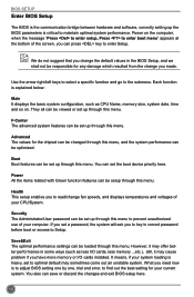
... CPU Name, memory size, system date, time and so on the computer, when the message "Press to enter setup, Press to Setup. If you set a password, the system will ask you change the default values in correct password before boot or access to enter boot menu" appears at the bottom of your system loading is to adjust BIOS setting one by one, trial and error, to find out the best setting...
... CPU Name, memory size, system date, time and so on the computer, when the message "Press to enter setup, Press to Setup. If you set a password, the system will ask you change the default values in correct password before boot or access to enter boot menu" appears at the bottom of your system loading is to adjust BIOS setting one by one, trial and error, to find out the best setting...

User Manual
Page 28
... and the setting is used to enable/disable it cannot. F1: General Help F2: Previous Values F3: Optimized Defaults F4: Save & Exit ESC/Right Click: Exit Version 2.16.1242. CPU Configuration BIOS SETUP Main F-center Advanced Boot CPU Configuration CPU Brand Name: Intel(R) Celeron(R) CPU J1900 @ 1.99GHz L1 Data Cache L1 Code Cache L2 Cache L3 Cache CPU Signature Max CPU Speed Min CPU Speed CPU Speed Processor Cores Intel HT Technology Intel VT-x Technology Intel SMX Technology Execute Disable Bit Limit...
... and the setting is used to enable/disable it cannot. F1: General Help F2: Previous Values F3: Optimized Defaults F4: Save & Exit ESC/Right Click: Exit Version 2.16.1242. CPU Configuration BIOS SETUP Main F-center Advanced Boot CPU Configuration CPU Brand Name: Intel(R) Celeron(R) CPU J1900 @ 1.99GHz L1 Data Cache L1 Code Cache L2 Cache L3 Cache CPU Signature Max CPU Speed Min CPU Speed CPU Speed Processor Cores Intel HT Technology Intel VT-x Technology Intel SMX Technology Execute Disable Bit Limit...

User Manual
Page 29
... disable CPU C6 (ACPI C3) report to OS. ► Package C State limit It is used to dynamically adjust processor voltage and core frequency, which can result in decreased average power consumption and decreased average heat production. CAUTION BIOS SETUP Enhanced Intel SpeedStep® technology (EIST) allows the system to select the C-State mode. 22 There are some system requirements must be met, including CPU, chipset, motherboard, BIOS...
... disable CPU C6 (ACPI C3) report to OS. ► Package C State limit It is used to dynamically adjust processor voltage and core frequency, which can result in decreased average power consumption and decreased average heat production. CAUTION BIOS SETUP Enhanced Intel SpeedStep® technology (EIST) allows the system to select the C-State mode. 22 There are some system requirements must be met, including CPU, chipset, motherboard, BIOS...

User Manual
Page 30
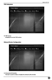
... Device. O.S. Trusted Computing Main F-center Advanced Boot Power Health Security Save&Exit Configuration Security Device Support Current Status Information NO Security Device Found [Disable] Enables or Disables BIOS support for security device. F1: General Help F2: Previous Values F3: Optimized Defaults F4: Save & Exit ESC/Right Click: Exit Version 2.16.1242. Copyright (C) 2013 American Megatrends, Inc. ► Trusted Computing/North Bridge/TXE Subsystem/Onboard Device Configuration/SATA Configuration/Super IO Configuration/Network Stack Configuration...
... Device. O.S. Trusted Computing Main F-center Advanced Boot Power Health Security Save&Exit Configuration Security Device Support Current Status Information NO Security Device Found [Disable] Enables or Disables BIOS support for security device. F1: General Help F2: Previous Values F3: Optimized Defaults F4: Save & Exit ESC/Right Click: Exit Version 2.16.1242. Copyright (C) 2013 American Megatrends, Inc. ► Trusted Computing/North Bridge/TXE Subsystem/Onboard Device Configuration/SATA Configuration/Super IO Configuration/Network Stack Configuration...

User Manual
Page 31
BIOS SETUP ► Security Device SUPPORT This item enables or disables BIOS support for security device. North Bridge Main F-center Advanced Boot Power Health Security Save&Exit North Bridge Configuration Memory Information Total Memory Memory Slot0 Memory Configuration 1024 MB (DDR3/DDR3L 1333) 1024 MB (DDR3/DDR3L 1333) DVMT Pre-Allocated DVMT Total Gfx Mem [256M] [256MB] Select DVMT 5.0 PreAllocated (Fixed) Graphics Memory size used by the Internal Graphics Devices. → ←: Select Screen ↑ ↓/Click...
BIOS SETUP ► Security Device SUPPORT This item enables or disables BIOS support for security device. North Bridge Main F-center Advanced Boot Power Health Security Save&Exit North Bridge Configuration Memory Information Total Memory Memory Slot0 Memory Configuration 1024 MB (DDR3/DDR3L 1333) 1024 MB (DDR3/DDR3L 1333) DVMT Pre-Allocated DVMT Total Gfx Mem [256M] [256MB] Select DVMT 5.0 PreAllocated (Fixed) Graphics Memory size used by the Internal Graphics Devices. → ←: Select Screen ↑ ↓/Click...
User Manual
Page 32
...;/Click: Select Item Enter/Dbl Click: Select +/-: Change Opt. F1: General Help F2: Previous Values F3: Optimized Defaults F4: Save & Exit ESC/Right Click: Exit Version 2.16.1242. Onboard Device Configuration Main F-center Advanced Boot Power Health Security Save&Exit Onboard Device Configuration Onboard LAN Controller Onboard USB Controller Legacy USB Support USB3.0 Support Azalia HD Audio controller [Enabled] [Enabled] [Enabled] [Enabled] [Enabled] Enabled/Disabled Onboard LAN Controller. → ←: Select Screen ↑ ↓/Click: Select Item Enter/Dbl Click: Select...
...;/Click: Select Item Enter/Dbl Click: Select +/-: Change Opt. F1: General Help F2: Previous Values F3: Optimized Defaults F4: Save & Exit ESC/Right Click: Exit Version 2.16.1242. Onboard Device Configuration Main F-center Advanced Boot Power Health Security Save&Exit Onboard Device Configuration Onboard LAN Controller Onboard USB Controller Legacy USB Support USB3.0 Support Azalia HD Audio controller [Enabled] [Enabled] [Enabled] [Enabled] [Enabled] Enabled/Disabled Onboard LAN Controller. → ←: Select Screen ↑ ↓/Click: Select Item Enter/Dbl Click: Select...

User Manual
Page 33
...SATA Configuration Main F-center Advanced Boot Power Health Security Save&Exit SATA Configuration Enable/Disable Serial ATA Onboard SATA Controller Onboard SATA Mode Serial-ATA Port 1 Serial-ATA Port 2 SATA Port0 Not Present SATA Port1 Not Present [Enabled] [Native IDE] [Enabled] [Enabled] → ←: Select Screen ↑ ↓/Click: Select Item Enter/Dbl Click: Select +/-: Change Opt. This configures the SATA ports to support native IDE mode. [AHCI] - The specification includes a description of your motherboard supporting AHCI, and you have a USB keyboard...
...SATA Configuration Main F-center Advanced Boot Power Health Security Save&Exit SATA Configuration Enable/Disable Serial ATA Onboard SATA Controller Onboard SATA Mode Serial-ATA Port 1 Serial-ATA Port 2 SATA Port0 Not Present SATA Port1 Not Present [Enabled] [Native IDE] [Enabled] [Enabled] → ←: Select Screen ↑ ↓/Click: Select Item Enter/Dbl Click: Select +/-: Change Opt. This configures the SATA ports to support native IDE mode. [AHCI] - The specification includes a description of your motherboard supporting AHCI, and you have a USB keyboard...
User Manual
Page 34
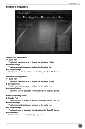
... Defaults F4: Save & Exit ESC/Right Click: Exit Version 2.16.1242. Serial Port 1 Configuration ► Serial Port This item is used to enable or disable the serial port (COM). ► Device Settings This item shows the resource assigned to the serial port. ► Change Settings This item is used to select an optimal settings for Super IO device. Super IO Configuration BIOS SETUP Main F-center Advanced Boot Power Health Security Save&Exit Super IO Configuration Super IO Chip ▶ Serial Port 1 Configuration...
... Defaults F4: Save & Exit ESC/Right Click: Exit Version 2.16.1242. Serial Port 1 Configuration ► Serial Port This item is used to enable or disable the serial port (COM). ► Device Settings This item shows the resource assigned to the serial port. ► Change Settings This item is used to select an optimal settings for Super IO device. Super IO Configuration BIOS SETUP Main F-center Advanced Boot Power Health Security Save&Exit Super IO Configuration Super IO Chip ▶ Serial Port 1 Configuration...
User Manual
Page 36
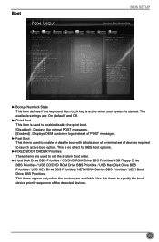
... Power Health [On] [Enabled] [Disabled] Security Save&Exit Select the keyboard NumLock state UEFI [UEFI Hard Disk] [UEFI CD/DVD] [UEFI USB Hard Disk] [UEFI USB CD/DVD] [UEFI USB Key] [UEFI USB Floppy] [UEFI Network] → ←: Select Screen ↑ ↓/Click: Select Item Enter/Dbl Click: Select +/-: Change Opt. This is no effect for BBS boot options. ► FIXED BOOT ORDER Priorities These items are : On (default) and Off. ► Quiet Boot This item is used to enable/disable the quiet boot. [Disabled] : Displays the normal POST messages. [Enabled] : Displays...
... Power Health [On] [Enabled] [Disabled] Security Save&Exit Select the keyboard NumLock state UEFI [UEFI Hard Disk] [UEFI CD/DVD] [UEFI USB Hard Disk] [UEFI USB CD/DVD] [UEFI USB Key] [UEFI USB Floppy] [UEFI Network] → ←: Select Screen ↑ ↓/Click: Select Item Enter/Dbl Click: Select +/-: Change Opt. This is no effect for BBS boot options. ► FIXED BOOT ORDER Priorities These items are : On (default) and Off. ► Quiet Boot This item is used to enable/disable the quiet boot. [Disabled] : Displays the normal POST messages. [Enabled] : Displays...
User Manual
Page 38
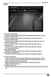
... [Enabled] [Enabled] [Enabled] [Disabled] [Disabled] [Enabled] [Power Off] Enable/Disable PS2 Keyboard/Mouse resume system. → ←: Select Screen ↑ ↓/Click: Select Item Enter/Dbl Click: Select +/-: Change Opt. Enabled: S1/S3/S4 is used to generate a wake up. ► Energy-using Products This item is normal, S5 wake up . Power BIOS SETUP Main F-center Advanced Boot Power Health Security Save&Exit Resume By PS2 KB/Mouse Resume By USB Device(s) Resume By PCIE Device(s) Resume By Onboard LAN...
... [Enabled] [Enabled] [Enabled] [Disabled] [Disabled] [Enabled] [Power Off] Enable/Disable PS2 Keyboard/Mouse resume system. → ←: Select Screen ↑ ↓/Click: Select Item Enter/Dbl Click: Select +/-: Change Opt. Enabled: S1/S3/S4 is used to generate a wake up. ► Energy-using Products This item is normal, S5 wake up . Power BIOS SETUP Main F-center Advanced Boot Power Health Security Save&Exit Resume By PS2 KB/Mouse Resume By USB Device(s) Resume By PCIE Device(s) Resume By Onboard LAN...

User Manual
Page 39
.... CPU Shutdowm Temperature CPU Smart Fan Control CPU Fan Stop Temperature CPU Fan Start Temperature CPU Fan Start PWM Value CPU Fan Slope PWM Value CPU Fan Delta Temperature System Smart Fan Control [Enabled] [Enabled] 0 35 120 3 2 [Disabled] → ←: Select Screen ↑ ↓/Click: Select Item Enter/Dbl Click: Select +/-: Change Opt. Copyright (C) 2013 American Megatrends, Inc. ► Case Open Warning This item is used to enable or disable case open chassis, Instruction Alarm will appear all the time. BIOS SETUP Health Main F-center Advanced Boot Power Health...
.... CPU Shutdowm Temperature CPU Smart Fan Control CPU Fan Stop Temperature CPU Fan Start Temperature CPU Fan Start PWM Value CPU Fan Slope PWM Value CPU Fan Delta Temperature System Smart Fan Control [Enabled] [Enabled] 0 35 120 3 2 [Disabled] → ←: Select Screen ↑ ↓/Click: Select Item Enter/Dbl Click: Select +/-: Change Opt. Copyright (C) 2013 American Megatrends, Inc. ► Case Open Warning This item is used to enable or disable case open chassis, Instruction Alarm will appear all the time. BIOS SETUP Health Main F-center Advanced Boot Power Health...
User Manual
Page 40
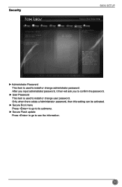
...; User Password This item is used to see the information. 33 F1: General Help F2: Previous Values F3: Optimized Defaults F4: Save & Exit ESC/Right Click: Exit Version 2.16.1242. Security BIOS SETUP Main F-center Advanced Boot Power Health Security Save&Exit Password Description Administrator Password User Password Administator Password ▶ Secure Boot menu ▶ Secure Flash update Not Installed Not Installed Set Administrator Password → ←: Select Screen ↑ ↓/Click: Select Item Enter...
...; User Password This item is used to see the information. 33 F1: General Help F2: Previous Values F3: Optimized Defaults F4: Save & Exit ESC/Right Click: Exit Version 2.16.1242. Security BIOS SETUP Main F-center Advanced Boot Power Health Security Save&Exit Password Description Administrator Password User Password Administator Password ▶ Secure Boot menu ▶ Secure Flash update Not Installed Not Installed Set Administrator Password → ←: Select Screen ↑ ↓/Click: Select Item Enter...

User Manual
Page 41
... Reset the system after clearing the CMOS values. Always load the Optimal defaults after updating the BIOS or after saving the changes. → ←: Select Screen ↑ ↓/Click: Select Item Enter/Dbl Click: Select +/-: Change Opt. Select [Yes] to exit setup utility and reset computer without saving your modifications, select [No] or to return to the main menu. ► Restore Defaults Optimal defaults are the best settings of connected devices...
... Reset the system after clearing the CMOS values. Always load the Optimal defaults after updating the BIOS or after saving the changes. → ←: Select Screen ↑ ↓/Click: Select Item Enter/Dbl Click: Select +/-: Change Opt. Select [Yes] to exit setup utility and reset computer without saving your modifications, select [No] or to return to the main menu. ► Restore Defaults Optimal defaults are the best settings of connected devices...

User Manual
Page 43
After that, you can click on each individual driver to Install 36 CD INSTRUCTION 4-1 Install driver and utility 1. Install Driver Use these options to install it manually. Manual Installation Step by Step Automatic Installation by One Click Drop to System Tray Exit the program Visit Foxconn's Show Utilities Show Drivers Browse CD View User's Manual website Choose the items you can click "One Click Setup" and then choose the items you want to install, or you want to install it first. You must click "Intel Chipset Driver" to install all the drivers for your system.
After that, you can click on each individual driver to Install 36 CD INSTRUCTION 4-1 Install driver and utility 1. Install Driver Use these options to install it manually. Manual Installation Step by Step Automatic Installation by One Click Drop to System Tray Exit the program Visit Foxconn's Show Utilities Show Drivers Browse CD View User's Manual website Choose the items you can click "One Click Setup" and then choose the items you want to install, or you want to install it first. You must click "Intel Chipset Driver" to install all the drivers for your system.
User Manual
Page 64
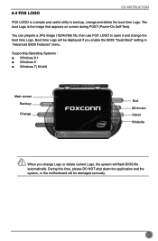
Supporting Operating Systems Windows 8.1 ■ Windows 8 ■ Windows 7( 64-bit) Main screen Backup Change Exit Minimize About Website CAUTION When you enable the BIOS "Quiet Boot" setting in "Advanced BIOS Features" menu. During this time, please DO NOT shut down the application and the system, or the motherboard will be displayed if you change the boot time Logo. You can prepare a JPG image (1024x768) file, then use FOX LOGO to backup...
Supporting Operating Systems Windows 8.1 ■ Windows 8 ■ Windows 7( 64-bit) Main screen Backup Change Exit Minimize About Website CAUTION When you enable the BIOS "Quiet Boot" setting in "Advanced BIOS Features" menu. During this time, please DO NOT shut down the application and the system, or the motherboard will be displayed if you change the boot time Logo. You can prepare a JPG image (1024x768) file, then use FOX LOGO to backup...


