
English Manual.
Page 6
... the Memory 11 Install an Expansion Card 13 Install other Internal Connectors 14 Jumpers 18 Chapter 3 BIOS Setup Enter BIOS Setup 22 Main Menu 22 Standard CMOS Features 24 Fox Central Control Unit 26 Advanced BIOS Features 29 Advanced Chipset Features 32 Integrated Peripherals 34 Security Chip Configuration 39 Power Management Setup 40...
... the Memory 11 Install an Expansion Card 13 Install other Internal Connectors 14 Jumpers 18 Chapter 3 BIOS Setup Enter BIOS Setup 22 Main Menu 22 Standard CMOS Features 24 Fox Central Control Unit 26 Advanced BIOS Features 29 Advanced Chipset Features 32 Integrated Peripherals 34 Security Chip Configuration 39 Power Management Setup 40...

English Manual.
Page 15
... CPU to install the CPU : ■ Make sure that supports HT Technology and has it does not meet the standard requirements for HT Technology ■ A BIOS that the motherboard supports the CPU. ■ Always turn on the CPU. Read the following guidelines before you may locate the notches on both sides...
... CPU to install the CPU : ■ Make sure that supports HT Technology and has it does not meet the standard requirements for HT Technology ■ A BIOS that the motherboard supports the CPU. ■ Always turn on the CPU. Read the following guidelines before you may locate the notches on both sides...

English Manual.
Page 18
... two channels : Channel 0 : DIMM1 Channel 1 : DIMM2 The combinations of the same capacity, brand, speed, and chips be installed in your system. It is installed, the BIOS will automatically check the memory in only one direction.
... two channels : Channel 0 : DIMM1 Channel 1 : DIMM2 The combinations of the same capacity, brand, speed, and chips be installed in your system. It is installed, the BIOS will automatically check the memory in only one direction.
English Manual.
Page 20
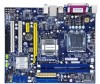
... on the card are completely inserted into the PCI Express x16 slot. Remove the metal slot cover from the slot. 13 If necessary, go to BIOS Setup to prevent hardware damage. Install the driver provided with your expansion card in the expansion slot. 1. Align the card with a screw. 5. CAUTION 2 2-3 Install an... card. ■ Always turn off the computer and unplug the power cord from the power outlet before installing an expansion card to make any required BIOS changes for your computer.
... on the card are completely inserted into the PCI Express x16 slot. Remove the metal slot cover from the slot. 13 If necessary, go to BIOS Setup to prevent hardware damage. Install the driver provided with your expansion card in the expansion slot. 1. Align the card with a screw. 5. CAUTION 2 2-3 Install an... card. ■ Always turn off the computer and unplug the power cord from the power outlet before installing an expansion card to make any required BIOS changes for your computer.

English Manual.
Page 24
The fan speed can be controlled and monitored in "PC Health Status" section of the BIOS Setup. Another 3-pin NB fan connector is used for S/PDIF output. 2 S/PDIF OUT Connector : SPDIF_OUT The connector is optional. +5V 1 EMPTY 2 SPDIF_OUT 3 GND 4 SPDIF_OUT GND ...
The fan speed can be controlled and monitored in "PC Health Status" section of the BIOS Setup. Another 3-pin NB fan connector is used for S/PDIF output. 2 S/PDIF OUT Connector : SPDIF_OUT The connector is optional. +5V 1 EMPTY 2 SPDIF_OUT 3 GND 4 SPDIF_OUT GND ...

English Manual.
Page 25
...closed Set Pin 2 and Pin 3 closed Set two pins closed . 4. Remove jumper cap from the power outlet. 2. Go to BIOS Setup to factory default when the BIOS settings were mistakenly modified. The following content carefully prior to your computer and turn it . Clear CMOS data is the fast way...Discharge) problem. This section explains how to it on this motherboard by a screwdriver for a few seconds, but using jumper cap is simply labeled as BIOS data, date, time information, hardware password...etc.). Turn off the computer, unplug the power cord from pins 2 and 3, put it onto pins 1...
...closed Set Pin 2 and Pin 3 closed Set two pins closed . 4. Remove jumper cap from the power outlet. 2. Go to BIOS Setup to factory default when the BIOS settings were mistakenly modified. The following content carefully prior to your computer and turn it . Clear CMOS data is the fast way...Discharge) problem. This section explains how to it on this motherboard by a screwdriver for a few seconds, but using jumper cap is simply labeled as BIOS data, date, time information, hardware password...etc.). Turn off the computer, unplug the power cord from pins 2 and 3, put it onto pins 1...

English Manual.
Page 26
... that can provide 500mA on . At the same time, a corresponding setting must not exceed the power supply capability (+5VSB) whether under normal condition or in BIOS as below: Set "CMOS Setup" -> "Power Management Setup" ->"Power Management Events" -> "USB KB Wake-Up From S3" to "Enabled". 1 +5V 2 (Default) 3 1 +5VSB 2 3 USBPW1357_1/ USBPW0246_1 ! ■...
... that can provide 500mA on . At the same time, a corresponding setting must not exceed the power supply capability (+5VSB) whether under normal condition or in BIOS as below: Set "CMOS Setup" -> "Power Management Setup" ->"Power Management Events" -> "USB KB Wake-Up From S3" to "Enabled". 1 +5V 2 (Default) 3 1 +5VSB 2 3 USBPW1357_1/ USBPW0246_1 ! ■...
English Manual.
Page 27
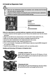
At the same time, the overclock bound depend on the keyboard or move the mouse, and a corresponding setting in the BIOS. 1 +5V 2 (Default) 3 1 +5VSB 2 3 KB/MS_PW Over Memory Frequency Jumper: JP1, JP2 When you use the memory which support 1066, the jumpers are used to enable ...
At the same time, the overclock bound depend on the keyboard or move the mouse, and a corresponding setting in the BIOS. 1 +5V 2 (Default) 3 1 +5VSB 2 3 KB/MS_PW Over Memory Frequency Jumper: JP1, JP2 When you use the memory which support 1066, the jumpers are used to enable ...
English Manual.
Page 28
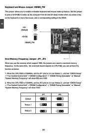
...: 1. You want to run the Setup Program when the following information : ■ Enter BIOS Setup ■ Main Menu ■ Standard CMOS Features ■ Fox Central Control Unit ■ Advanced BIOS Features ■ Advanced Chipset Features ■ Integrated Peripherals ■ Security Chip Configuration ■ ... ■ Save & Exit Setup ■ Exit Without Saving Since BIOS could be updated some other times, the BIOS information described in the future. We do not guarantee the content of the BIOS parameters are also provided. An error message appears on the screen during...
...: 1. You want to run the Setup Program when the following information : ■ Enter BIOS Setup ■ Main Menu ■ Standard CMOS Features ■ Fox Central Control Unit ■ Advanced BIOS Features ■ Advanced Chipset Features ■ Integrated Peripherals ■ Security Chip Configuration ■ ... ■ Save & Exit Setup ■ Exit Without Saving Since BIOS could be updated some other times, the BIOS information described in the future. We do not guarantee the content of the BIOS parameters are also provided. An error message appears on the screen during...

English Manual.
Page 29
...to enter SETUP, ESC to enter SETUP. ! AwardBIOS CMOS Setup Utility ► Standard CMOS Features ► Fox Central Control Unit ► Advanced BIOS Features ► Advanced Chipset Features ► Integrated Peripherals ► Security Chip Configuration ► Power Management Setup Esc : Quit F10 : Save & ... All onboard peripherals can be set up through this menu. ► Fox Central Control Unit Some special proprietary features (such as BIOS ID, system date, time and floppy drive. Use the arrow keys to select a specific item and press to go to maintain...
...to enter SETUP, ESC to enter SETUP. ! AwardBIOS CMOS Setup Utility ► Standard CMOS Features ► Fox Central Control Unit ► Advanced BIOS Features ► Advanced Chipset Features ► Integrated Peripherals ► Security Chip Configuration ► Power Management Setup Esc : Quit F10 : Save & ... All onboard peripherals can be set up through this menu. ► Fox Central Control Unit Some special proprietary features (such as BIOS ID, system date, time and floppy drive. Use the arrow keys to select a specific item and press to go to maintain...
English Manual.
Page 30
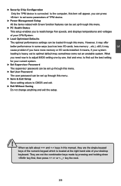
... related with Green function features can be set to optimal default may sometimes come out an unstable system. What you need now is to adjust BIOS setting one by pressing and holding down key first, then press or key the next. 23 CAUTION 3 ► Security Chip Configuration Only the TPM device...
... related with Green function features can be set to optimal default may sometimes come out an unstable system. What you need now is to adjust BIOS setting one by pressing and holding down key first, then press or key the next. 23 CAUTION 3 ► Security Chip Configuration Only the TPM device...

English Manual.
Page 31
...9658; Time - : : format This item allows you to enable or disable this drive. [None] means no HDD is used to set up by BIOS (Read Only). AwardBIOS CMOS Setup Utility Standard CMOS Features Date (mm:dd:yy) Thu, Jan 10 2008 Item Help Time (hh:mm:ss) 17... These categories identify the hard disks connected to the PATA and SATA ports in .] Halt On [All , But Keyboard] Installed Memory 1024M BIOS ID G31M04-GA20.F1.P.04 Move Enter:Select +/-/PU/PD:Value F10:Save ESC:Exit F1:General Help F5: Previous Values F7: Optimized Defaults ...
...9658; Time - : : format This item allows you to enable or disable this drive. [None] means no HDD is used to set up by BIOS (Read Only). AwardBIOS CMOS Setup Utility Standard CMOS Features Date (mm:dd:yy) Thu, Jan 10 2008 Item Help Time (hh:mm:ss) 17... These categories identify the hard disks connected to the PATA and SATA ports in .] Halt On [All , But Keyboard] Installed Memory 1024M BIOS ID G31M04-GA20.F1.P.04 Move Enter:Select +/-/PU/PD:Value F10:Save ESC:Exit F1:General Help F5: Previous Values F7: Optimized Defaults ...
English Manual.
Page 32
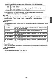
...other errors. ► Installed Memory These are Display-Only information of the system memory, determined by POST(Power On Self Test) of the BIOS. ► BIOS ID This item shows the information of the Floppy Disk Drive is detected during powering up. All Errors No Errors All, But Keyboard All,... But Diskette All, But Disk/Key Whenever the BIOS detects a nonfatal error, the system will stop and you to [Auto] , the system can be [360KB, 5.25 in], [1.2MB, 5.25 in], [720KB, 3.5 in], [1....
...other errors. ► Installed Memory These are Display-Only information of the system memory, determined by POST(Power On Self Test) of the BIOS. ► BIOS ID This item shows the information of the Floppy Disk Drive is detected during powering up. All Errors No Errors All, But Keyboard All,... But Diskette All, But Disk/Key Whenever the BIOS detects a nonfatal error, the system will stop and you to [Auto] , the system can be [360KB, 5.25 in], [1.2MB, 5.25 in], [720KB, 3.5 in], [1....

English Manual.
Page 33
... Increase this ratio, you can manually select a CPU clock to auto detect PCI slots. Same definition as [Step 1]. [Manual] - CPU is a BIOS write-protection mechanism provided. Same definition as [Step 1]. [Step 3] - The available setting values are : [Default], [Manual], [Step1], [Step2] ...and [Step 3]. [Default] - Any selected setting must be saved and exit BIOS to reduce EMI (Electromagnetic Interference). ► Fox Intelligent Stepping (FIS) You can get the CPU speed. SuperBIOS Protect function protects your system....
... Increase this ratio, you can manually select a CPU clock to auto detect PCI slots. Same definition as [Step 1]. [Manual] - CPU is a BIOS write-protection mechanism provided. Same definition as [Step 1]. [Step 3] - The available setting values are : [Default], [Manual], [Step1], [Step2] ...and [Step 3]. [Default] - Any selected setting must be saved and exit BIOS to reduce EMI (Electromagnetic Interference). ► Fox Intelligent Stepping (FIS) You can get the CPU speed. SuperBIOS Protect function protects your system....

English Manual.
Page 36
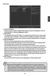
...are small, fast memory caches that the first/second/third boot devices failed. ► Boot Up Floppy Seek This item controls whether the BIOS will not detect the floppy. ► Boot Up NumLock Status This item defines if the keyboard Num Lock key is active when your ... cache. The available settings are built into a CPU and help speed access to enable/disable the Hyper-Threading feature. AwardBIOS CMOS Setup Utility Advanced BIOS Features ► CPU Feature ► Removable Device Priority ► Hard Disk Boot Priority CPU L1 & L2 Cache Hyper-Threading Technology First Boot...
...are small, fast memory caches that the first/second/third boot devices failed. ► Boot Up Floppy Seek This item controls whether the BIOS will not detect the floppy. ► Boot Up NumLock Status This item defines if the keyboard Num Lock key is active when your ... cache. The available settings are built into a CPU and help speed access to enable/disable the Hyper-Threading feature. AwardBIOS CMOS Setup Utility Advanced BIOS Features ► CPU Feature ► Removable Device Priority ► Hard Disk Boot Priority CPU L1 & L2 Cache Hyper-Threading Technology First Boot...
English Manual.
Page 38
... systems can halt worm attacks, reducing the need for WinXP. ► C1E Function C1E represents Enhanced HALT State. Should be met, including CPU, chipset, motherboard, BIOS and operation system. Replacing older computers with anti-virus, firewall, spyware removal, e-mail filtering software, and other initiatives. ► EIST Function You can execute and...
... systems can halt worm attacks, reducing the need for WinXP. ► C1E Function C1E represents Enhanced HALT State. Should be met, including CPU, chipset, motherboard, BIOS and operation system. Replacing older computers with anti-virus, firewall, spyware removal, e-mail filtering software, and other initiatives. ► EIST Function You can execute and...
English Manual.
Page 39
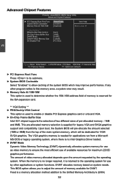
... SVGA graphics. DVMT allocates memory based on system needs. AwardBIOS CMOS Setup Utility Advanced Chipset Features ► PCI Express Root Port Func System BIOS Cacheable Memory Hole At 15M-16M [Press Enter] Item Help [Enabled] [Disabled] Menu Level ► ** VGA Setting ** PEG/Onchip ... F1:General Help F5: Previous Values F7: Optimized Defaults ► PCI Express Root Func Press to its submenu. ► System BIOS Cacheable Select "Enabled" to allow caching of memory available for legacy VGA and SVGA graphics support and compatibility. If any other applications...
... SVGA graphics. DVMT allocates memory based on system needs. AwardBIOS CMOS Setup Utility Advanced Chipset Features ► PCI Express Root Port Func System BIOS Cacheable Memory Hole At 15M-16M [Press Enter] Item Help [Enabled] [Disabled] Menu Level ► ** VGA Setting ** PEG/Onchip ... F1:General Help F5: Previous Values F7: Optimized Defaults ► PCI Express Root Func Press to its submenu. ► System BIOS Cacheable Select "Enabled" to allow caching of memory available for legacy VGA and SVGA graphics support and compatibility. If any other applications...

English Manual.
Page 42
...] : SATA is operating in [Enhanced Mode], you can refer to use the slower PIO transfer mode. Disabling DMA support will force the drive to this BIOS feature at PATA port. [Combined Mode] : PATA and SATA are combined, maximum there are supported. You should only disable it . *** On-Chip Serial ATA Setting...
...] : SATA is operating in [Enhanced Mode], you can refer to use the slower PIO transfer mode. Disabling DMA support will force the drive to this BIOS feature at PATA port. [Combined Mode] : PATA and SATA are combined, maximum there are supported. You should only disable it . *** On-Chip Serial ATA Setting...
English Manual.
Page 45
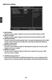
...], the USB device operates on full/low speed. ► USB Keyboard Function This item is used to auto or enabled. ► ***USB Mass Storage Device*** BIOS auto detects the presence of USB Mass Storage Devices, you have a USB mouse, set the USB operation mode. Setting Options: [Auto]; [FDD Mode]; [HDD Mode...
...], the USB device operates on full/low speed. ► USB Keyboard Function This item is used to auto or enabled. ► ***USB Mass Storage Device*** BIOS auto detects the presence of USB Mass Storage Devices, you have a USB mouse, set the USB operation mode. Setting Options: [Auto]; [FDD Mode]; [HDD Mode...

English Manual.
Page 47
...that defines power and configuration management interfaces between the S5 state and the S4 state to allow for initial boot operations within the BIOS to distinguish whether or not the boot is responsible for example, Windows2000 or WindowsXP). In this state, no system context is ...cache, and chip set ) and hardware maintains all devices. Software uses a different state value to distinguish between an operating system and the BIOS. Power Management Setup Phoenix - The S3 sleeping state is a low wake latency sleeping state where all system context is in this function the...
...that defines power and configuration management interfaces between the S5 state and the S4 state to allow for initial boot operations within the BIOS to distinguish whether or not the boot is responsible for example, Windows2000 or WindowsXP). In this state, no system context is ...cache, and chip set ) and hardware maintains all devices. Software uses a different state value to distinguish between an operating system and the BIOS. Power Management Setup Phoenix - The S3 sleeping state is a low wake latency sleeping state where all system context is in this function the...


